GRASS VALLEY Kayak HD Installation And Service Manual
Digital production switcher
Hide thumbs
Also See for Kayak HD:
- Installation and service manual (216 pages) ,
- Installation planning manual (60 pages) ,
- Datasheet (8 pages)

Subscribe to Our Youtube Channel
Related Manuals for GRASS VALLEY Kayak HD


Summary of Contents for GRASS VALLEY Kayak HD
- Page 1 Kayak HD DIGITAL PRODUCTION SWITCHER Installation and Service Manual SOFTWARE VERSION 6.8.0 071844800 DECEMBER 2005...
- Page 2 +33 1 45 29 73 00 Germany, Europe +49 6150 104 782 +49 6150 104 223 Copyright © Grass Valley. All rights reserved. Grass Valley Web Site www.thomsongrassvalley.com web site offers the following: — Current versions of product catalogs, brochures,...
-
Page 3: Table Of Contents
1.5 and 2 M/E Control Panel ........Kayak HD Video Processor 4 RU Frame ....... . - Page 4 Kayak HD 100C Control Cabling ........
-
Page 5: Kayakhd Installation And Service Manual
Change the Kayak HD Frame Battery ........ - Page 6 Contents KayakHD Installation and Service Manual...
-
Page 7: Preface
The User Manual contains background information about the Kayak HD Digital Production switcher and describes operating procedures. This manual can be used while learning about Kayak HD and for enhancing your basic knowledge of the system. The Installation and Service Manual contains information about installing, configuring, and maintaining the system. - Page 8 Preface KayakHD Installation and Service Manual...
-
Page 9: Regulatory Notices
Changes or modifications not expressly approved by Grass Valley Group can affect emission compliance and could void the user’s authority to operate this equipment. -
Page 10: Canadian Certified Power Cords
Regulatory Notices Canadian Certified Power Cords Canadian approval includes the products and power cords appropriate for use in the North America power network. All other power cords supplied are approved for the country of use. Canadian Certified AC Adapter Canadian approval includes the AC adapters appropriate for use in the North America power network. - Page 11 Regulatory Notices Category Standard Designed/tested for compliance with: EMC Directive 89/336/EEC via Audio, Video and Entertainment Lighting Control for the European EN 55103-1 and 2 Community. EN 55103-1 standards Electromagnetic compatibility. Product family standard for audio, video, audio-visual and entertain- ment lighting control apparatus for professional use.
- Page 12 Regulatory Notices KayakHD Installation and Service Manual...
-
Page 13: Safety Summary
Safety Summary Read and follow the important safety information below, noting especially those instructions related to risk of fire, electric shock or injury to persons. Additional specific warnings not listed here may be found throughout the manual. WARNING Any instructions in this manual that require opening the equipment cover or enclosure are for use by qualified service personnel only. -
Page 14: Symbols On The Product
Safety Summary Symbols on the Product The following symbols may appear on the product: Indicates that dangerous high voltage is present within the equipment enclosure that may be of sufficient magnitude to constitute a risk of electric shock. Indicates that user, operator or service technician should refer to product manual(s) for important operating, maintenance, or service instructions. -
Page 15: Cautions
Safety Summary — Use only the power cord supplied or specified for Use proper power cord this product. — Connect the grounding conductor of the power cord to Ground product earth ground. — Do not operate this Operate only with covers and enclosure panels in place product when covers or enclosure panels are removed. - Page 16 Safety Summary — If you suspect product damage Do not operate with suspected equipment failure or equipment failure, have the equipment inspected by qualified service personnel. — If mains switch is not provided, the power cord(s) Ensure mains disconnect of this equipment provide the means of disconnection. The socket outlet must be installed near the equipment and must be easily accessible.
-
Page 17: Section 1 - System Overview
• Kayak HD 100C, which includes a 1 M/E Control Panel and a compact 4 RU Video Processor Frame • Kayak HD 150C, which includes a 2 M/E Control Panel and a 4 RU Video Processor Frame frame equipped with one M/E module •... - Page 18 .5 M/E includes cuts and mixes, no wipes or iDPM, with simple linear/lumi- nance keyers and no chroma keys. • Number of inputs: • 24 for Kayak HD 100C, 150C • 48 for Kayak HD 200C • Number of outputs: •...
-
Page 19: Options
• Control Systems (Grass Valley Andromeda™ and third-party systems) • Grass Valley under monitor displays • Grass Valley external Remote Aux Panels • ESAM II for audio-follow-video applications • Edit controllers (native and Grass Valley Model 100 and 200) KayakHD Installation and Service Manual... -
Page 20: System Components
Kayak HD Production Switcher systems use a control panel with an inte- grated menu display (color TFT with touch-screen). Kayak HD 100C systems use a 1 M/E panel, and the Kayak HD 150C and 200C systems use a 2 M/E Control panel. -
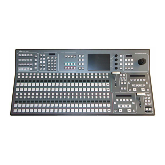
Page 21: 1.5 And 2 M/E Control Panel
System Components 1.5 and 2 M/E Control Panel Figure 3. Kayak HD 150C, 200C, and 200 Control Panel Figure 4. 2 M/E Control Panel, Rear View PS/2 Port USB #4 P/S 2 (future use) (future use) Redundant 48V DC Power In... -
Page 22: Kayak Hd Video Processor 4 Ru Frame
Section 1 — System Overview Kayak HD Video Processor 4 RU Frame Figure 5. Kayak HD 4RU Frame, Front View with Door Removed Top M/E Slot Controller Flash Power Reset 2 USB Bottom M/E Slot (M/E 1) and 0.5 M/E... -
Page 23: Kdd-Psu Power Supply Option
KDD-PSU Power Supply Option The KDD-PSU option is a one-rack unit, wide range AC power supply pro- viding power for a remotely-mounted Kayak HD Control Panel or for each additional Control Panel connected to the same processor chassis. Power output is sufficient for two 1 M/E systems or one 2 M/E system. -
Page 24: Video Signal Flow
Video Signal Flow The basic video signal flow (Figure 8 on page 25) of the Kayak HD system has been designed for operational flexibility. For example, all the outputs from the M/E are routed back to the video crosspoint matrix, making all these signals accessible to the entire system. - Page 25 Video Signal Flow Figure 8. Kayak HD Video Signal Flow Main Board Crosspoint 144 x 144 M/E 1 Mix Effect Board Variable Delay Video Proc Σ Variable Delay Σ Video Proc Variable Delay Video Proc Σ Variable Delay Σ Video Proc...
- Page 26 Section 1 — System Overview KayakHD Installation and Service Manual...
-
Page 27: Section 2 - Installation
Section Installation Pre-Installation Procedures Before you physically install the Kayak HD system, familiarize yourself with the tools required, physical specifications, and safety and power requirements covered in this section. System Survey Check all parts received against the packing list enclosed with your ship- ment, and examine the equipment for any shipping damage. -
Page 28: Safety Requirements
CAUTION To avoid static damage to sensitive electronic devices, protect the Kayak HD system from static discharge. Avoid handling frame modules in a high static environment. -
Page 29: General Rack Mounting Instructions
(leakage) currents for all power supplies does not exceed 3.5 mA. Video Processor Frame Installation 4 RU Compact Frame Dimensions Figure 9. Kayak HD 4 RU Frame Dimensions 482 mm 19.0 in. 465 mm 18.31 in. - Page 30 Section 2 — Installation Figure 10. Kayak HD 4 RU Frame Dimensions 442 mm 17.4 in. 541 mm 523 mm 21.29 in. 20.58 in. 37 mm 1.43 in. Top view KayakHD Installation and Service Manual...
-
Page 31: Ru Compact Frame Rack Mounting
The front door lifts off vertically and must have suf- ficient clearance room in order to remove it. If you have equipment mounted too close to the Kayak HD 4 RU Compact Frame, you may not be able to remove the door. -
Page 32: Internal Redundant Power Supply Option
The front door lifts off vertically and must have suf- ficient clearance room in order to remove it. If you have equipment mounted too close to the Kayak HD 4 RU Compact Frame, you may not be able to remove the door. - Page 33 Video Processor Frame Installation To remove the Kayak HD frame door: 1. Turn the lock on the front door of the Kayak HD Frame 180-degrees counterclockwise to unlock it. 2. Open the door to less than 90-degrees from the Frame.
-
Page 34: Control Panel Installation
Section 2 — Installation Control Panel Installation 1 M/E Control Panel Figure 14. Kayak HD 100C Control Panel Dimensions 1 of 2 418 mm 16.46 in. 260 mm 10.23 in. 66 mm 2.55 in. 16 mm 0.60 in. 34 mm 81 mm 1.31 in. - Page 35 Control Panel Installation Figure 15. Kayak HD 100C Control Panel Dimensions 2 of 2 Front view 10 mm 428 mm 10 mm 0.39 in. 16.85 in. 0.39 in. 448 mm 17.64 in. 418 mm 16.5 in. Top view 448 mm 17.64 in.
-
Page 36: 2 M/E Control Panel
Section 2 — Installation 2 M/E Control Panel Figure 16. Kayak HD 150C and 200C Control Panel Dimensions 1 of 2 418 mm 16.46 in. 260 mm 10.23 in. 16 mm 65 mm 0.60 in. 2.55 in. 34 mm 1.31 in. -
Page 37: Panel Mounting Options
Control Panel Installation Figure 17. Kayak HD 150C, 200C, and 200 Control Panel Dimensions 2 of 2 Front view 10 mm 10 mm 789 mm 0.39 in. 31.1 in. 0.39 in. 809 mm 31.9 in. 418 mm Top view 16.5 in. -
Page 38: Surface Mount Cutout Dimensions
Section 2 — Installation Surface Mount Cutout Dimensions Table 1. Kayak HD Surface Mount Cutout Dimensions Cutout Dimensions Control Surfaces Kayak HD 150C, 200C 400 mm (15.75 in.) 791 mm (31.14 in.) Kayak HD 100C 400 mm (15.75 in.) 430 mm (16.93 in.) CAUTION At least 50 mm (2 in.) of clear space on the sides of the panel below the... -
Page 39: Kdd-Psu Power Supply Option
Control Panel Installation KDD-PSU Power Supply Option The KDD-PSU is a 1RU frame designed for rack mounting as shown in Figure Figure 19. KDD-PSU Rack Installation Cut fastening metal so that the ventilation openings are not covered KayakHD Installation and Service Manual... -
Page 40: Pin Assignments
There is an RS232 serial port, a keyboard port, and a VGA video output located on front of the Controller Board. These ports are used for diagnos- tics. If you need to use these ports to diagnose problems with the Kayak HD switcher, please contact your Grass Valley Customer Service Representa- tive. -
Page 41: Control Panel Dc Power In
Pin Assignments Control Panel DC Power In Table 3. Socket Signal 48 V (+) 48 V (-) D-Sub Male Pin 1 Pin 2 Pin A1 Pin A2 Pin 3 Pin 5 Frame DC Power Out Table 4. Socket Pin Signal 48 V (+) 48 V (-) D-Sub Female... -
Page 42: Tally Adapter
Figure 20. Tally Adapter GPI / Tally Connections The Kayak HD GPI / Tally system has 32 universal relays that interface source tally and GPI Output information to an external system through the Tally Port connector. The channels can be assigned in the Setup menu. -
Page 43: Gpi Outputs
GPI / Tally Connections Since the circuit ground is led out of the device, the cabling has to be shielded for this kind of control. Non-shielded cables may cause EMC and/ or ESD problems. To activate a GPI In you must provide switch closure between a particular GPI In pin and one of the two GPI In Com pins (Pins 1 and 34). - Page 44 Section 2 — Installation 4 RU Frame GPI/O – Tally (GPI In 1-8, GPI Out 1-32) Socket Ribbon Cable 50-Pin D-Sub Signal GPIInCom GPIInCom D-50 Female GPIIn1 Pin 18 GPIIn2 GPIIn3 Pin 1 GPIIn4 Pin 34 GPIIn5 GPIIn6 GPIIn7 GPIIn8 GPIOutComA GPIOut1A GPIOut2A...
- Page 45 GPI / Tally Connections 4 RU Frame GPI/O – Tally (GPI In 9-16, GPI Out 33-64) Socket Ribbon Cable 50-Pin D-Sub Signal GPIInCom GPIInCom D-50 Female GPIIn9 Pin 18 GPIIn10 GPIIn11 Pin 1 GPIIn12 Pin 34 GPIIn13 GPIIn14 GPIIn15 GPIIn16 GPIOutComJ GPIOut33J GPIOut34J...
-
Page 46: Cabling
Cabling The Kayak HD system uses Ethernet, serial, and USB connections. Tally and GPI/O control are also available. A simple Kayak HD system con- sisting of a Control Panel and Video Processor frame does not require con- nection to an external Ethernet Local Area Network (LAN). The video processor frame incorporates an Ethernet switch for this purpose. -
Page 47: Kayak Hd 150C And 200C Control Cabling
Cabling Kayak HD 150C and 200C Control Cabling Figure 22. Kayak HD 150C or 200C Standard Control Cabling PS/2 2 USB Port Ports P/S 2 Control Panel Supplied CAT5 Cable Video Processor Frame LINK/ACTIVITY OFF-10 AMBER-100 GREEN-1000 Supplied DC Interconnect Cable... -
Page 48: Network Cabling
Managed capability. CAUTION An existing facility Ethernet switch (not hub) can support Kayak HD if an ade- quate number of ports are available. Keep your facility network and technical network separate in order to avoid network traffic negatively affecting Kayak HD system operation. -
Page 49: Factory Network Settings
Note In order to integrate Kayak HD devices into an existing network, ask the local network administrator for the subnet mask of the network. Before changing IP addresses always set the subnet masks of the Kayak HD devices to the mask of the local network. -
Page 50: Outputs
Kayak HD Video Timing Kayak HD Home - Install Menu 1. To begin setting the Video Timing for the Kayak HD switcher press the Home key on the switcher control panel to go to the menu on the Home Kayak HD switcher menu screen. - Page 51 E-Box Genlock Genlock Genlock menu reports the status of the Kayak HD system sync generator. It is used to switch between HD and SD operating modes and to adjust the internal system timing. Figure 24. Genlock Menu with Video Signal in Green Legal Timing Window...
- Page 52 NONE Note The Kayak HD cannot support both SD and HD at the same time; you must choose one mode or the other. If you change the mode from SD to HD (or vice versa) then the Kayak HD hardware must reprogram itself to process the change.
-
Page 53: Select The Video Standard
Kayak HD Video Timing The Asynchronous buses window in the upper left of the menu Genlock shows an overview of the buses for the entire switcher: • PP • ME1 • ME2 • ME3 • AUX If any bus is displayed in the... -
Page 54: Select The Video Reference Source
Section 2 — Installation 2. Press to select the video standard you wish to use for the Kayak HD switcher. If you select either the Kayak HD SD Auto Detect HD Auto Detect system will automatically determine the appropriate video standard to apply for your switcher based on the external reference. -
Page 55: Select Sf Mode
Kayak HD frame. Select SF Mode The Kayak HD system supports 1080sf (segmented frame) video formats at 23.9, 24, 25 and 30 fps. Segmented frame video captures a frame of video progressively, but displays the frame as two interlaced fields. - Page 56 Section 2 — Installation To select the SF mode for the Kayak HD switcher: Figure 28. Genlock Menu with HD Auto Preselect SF Mode Data Pad 1. From the bottom of the menu press the button located in the Genlock...
-
Page 57: Adjust Internal System Timing
Adjusting the Phase affects the phase of all inputs and outputs of the switcher with respect to the external reference. Grass Valley recommends that you use the AUX1 bus to check the video timing of all inputs. This compares the video source selected on the AUX1 bus to the switcher’s internal system timing. - Page 58 Genlock menu is not displayed, press the E-Box button and select Genlock. 4. On the Kayak HD control panel press a key to select a video source from the AUX 1 bus. You need to check all video sources for timing.
- Page 59 Kayak HD Video Timing 5. Observe the vertical black cursor in the timing window to see how the source you have selected compares with the internal system timing. Now adjust the internal system timing by physically turning the Genlock located to the right of the menu screen, third knob from the Phase Knob top.
-
Page 60: Kayak System Control Via Pc
To connect a computer to the Kayak HD you will need: • Laptop or desktop computer with an available Ethernet port • 2 Ethernet Cables (1:1) Connect the computer, frame, and the Kayak HD Panel as shown in Figure Figure 32. Connecting a Computer to the Kayak HD... - Page 61 Kayak System Control via PC Configure your computer to connect to the Kayak HD by specifying the IP address for your computer using this format: IP Address 192.168.0.xxx Subnet Mask: 255.255.255.0 To set the Identification for your computer and workgroup change your Network Properties to reflect your computer name and workgroup (if required).
- Page 62 Section 2 — Installation KayakHD Installation and Service Manual...
-
Page 63: Section 3 - Configuration
Configuration Introduction This section provides system configuration information for the Kayak HD Digital Production Switcher. Refer to the latest Kayak HD Release Notes for information specific to your current software version. Configuration Steps Kayak HD system configuration includes the following basic steps: 1. -
Page 64: Installing The Sidepanel Software On A Computer
Installing the Sidepanel Software on a Computer 1. Connect your computer to the Kayak HD. (Refer to Figure 32 on page 60.) 1. Insert the Kayak HD Software CD into your computer’s CD-ROM drive. 2. Navigate to this directory on the CD-ROM: \Kayak\OperatingSoftware\Ds0206\ds0206.xxx\DS0203.4 xx\Disk1 3. - Page 65 Installing the Sidepanel Software on a Computer Figure 34. Sidepanel Software Setup Screen 5. Choose the type of installation you wish to perform: CAUTION Be careful when selecting the type of software installation to use. This setting cannot be changed later. Demo version, no connection to a panel or a frame.
- Page 66 Section 3 — Configuration Figure 35. Sidepanel Keyboard Serial Interface screen 7. Enter the serial Interface line of the Sidepanel Keyboard (if available) and click Next Figure 36. Sidepanel Software Desktop Picture Option 8. Click to select the checkbox for and click Desktop Picture Next...
- Page 67 9. Click to select the checkbox for “Yes, I want to restart my computer now” click Finish To complete the computer connection to the Kayak HD after the computer has rebooted: 1. Launch the Sidepanel software application 2. Right-click the...
-
Page 68: Device Configuration
Section 3 — Configuration Device Configuration Configure Device Menu You can change device configuration data from the Kayak HD Configure Device menu. To display the menu: Configure Device 1. From the Kayak HD menu screen, click the button. Home Install 2. - Page 69 Device Configuration 4. Click the button at the bottom of the menu Config. Device Device Control screen to display the menu Configure Device Figure 39. Configure Device Menu From the Configure Device menu you can change configuration data using these buttons: •...
-
Page 70: Set Date And Time In Configure Device Menu
Section 3 — Configuration Set Date and Time in Configure Device Menu Figure 40. Config Device Menu 1. From the menu click to select the name of either the panel Device Control or the frame from the scrolling list on the left. 2. -
Page 71: Reset / Check / Clear Device Menu
Device Configuration Reset / Check / Clear Device Menu From the Device Control menu you can click the button to Reset Device display the menu. Only qualified users should Reset/Check/Clear Device attempt to configure these functions: • Start/Restart the device Reset Device: •... -
Page 72: Main Panel Adjustments
Section 3 — Configuration Main Panel Adjustments Touchscreen Calibration To open the menu: Touchscreen Calibration 1. From the Kayak HD menu click . The Home Install Touchscreen Calibration data pad displays on the screen. If the data pad is not displayed at first, click the... -
Page 73: Introduction
Troubleshooting and Diagnostics The Kayak HD Digital Production Switcher is designed for ease of service and includes diagnostic functions for fast and effective troubleshooting of the system. This information is for troubleshooting a Kayak HD system that was installed and working properly prior to experiencing any failures. -
Page 74: Grass Valley Customer Service Faq Database
Software Update Recommended USB Flash Drives Kayak HD software installation requires a USB Flash Drive. A 128MB USB flash drive is supplied with your switcher. The following types of USB flash drives are approved for use with the Kayak HD switcher: •... -
Page 75: Installing Software On The Usb Flash Drive
Software Update http://www.sandisk.com/consumer/cruzermini.asp • Twinmos Mobile DiskIII 128MB Note USB Setup does not detect this device as a removable device. http://www.twinmos.com • PQI Corp.: Intelligent Stick 1GB, CoolDrive 512MB, CoolDrive 1GB http://www.pqi1st.com/products/istick.asp Installing Software on the USB Flash Drive 1. Plug a USB flash drive into a standard desktop PC or laptop. 2. - Page 76 Section 4 — Maintenance 5. Press the button inside the window. Next Welcome Figure 43. Welcome screen 6. The installation program scans the system for removable devices to determine the destination folder. If the folder displayed doesn't match your USB installation device, choose another folder by clicking the button to navigate to the directory you want.
- Page 77 Software Update Figure 44. Choose Destination Location screen 7. Click to display the window. Next Component Information Figure 45. Component Information Window 8. Click to select the checkbox for the version of the software you want to install on your USB device. You can select more than one version. KayakHD Installation and Service Manual...
- Page 78 Grass Valley recommends installing software onto the USB flash drive directly from the original CD-ROM. Never delete or change files on an suc- cessfully installed USB flash drive. This prevents failure of the Kayak HD soft- ware installation process. Note USB ports 1 and 3 are not supported on Kayak HD control panel.
-
Page 79: Loading And Updating Software
Installing Software on the USB Flash Drive on page 75 1. Plug the USB flash drive into either USB port 2 or 4 on the Kayak HD control panel. If the USB flash drive doesn't fit (mechanically) into the USB 4 slot use the extension cable that comes with your switcher as an adapter. -
Page 80: Section 4 - Maintenance
Section 4 — Maintenance 4. Click the button. The dialog box displays. Softw. Update Software Update Figure 48. Device Control Menu with Software Update Dialog Box KayakHD Installation and Service Manual... - Page 81 Software Update 5. Click either the or the button. The correct software Start Install Install Part.x will be installed in the respective device (MF or CP) automatically. Two partitions are available on the USB flash drive for the application software. Clicking Start Install installs the software in the non-active partition...
-
Page 82: Installation Procedure
Section 4 — Maintenance Installation Procedure CAUTION Do not remove the USB flash drive during installation. CAUTION Do not abort installation while installing on the Active partition! If you stop the installation process on the Active partition the switcher will not function. 1. - Page 83 Software Update Figure 51. Device Control Installation Failure Status on Partition 2 2. After finishing the installation procedure, a dialog box displays the question, Do you want to reset the device now? Figure 52. Finish Installation Note Verify that the active partition shows the new software version you just installed (e.g., 6.8.0) before restarting the device.
-
Page 84: Updating The Cpld Firmware
Section 4 — Maintenance 3. If the active partition shows that the new software was successfully installed click . The installed software is available only after you restart the system. Note Always restart each device after upgrading its software. Updating the CPLD Firmware At the end of each installation process the system checks to determine if a CPLD update is necessary. -
Page 85: Troubleshooting And Diagnostics
Troubleshooting and Diagnostics CAUTION Do not change to any menu other than the Device Control menu after initi- ating an CPLD update on a Kayak frame. Changing menus prevents you from being able to monitor the update process. After the CPLD update is finished the system must be restarted to set the device for normal operation. - Page 86 Start Pinging Stop Pinging 5. When the required ping information has been obtained, click the Stop button. Grass Valley recommends that you test your connection Pinging using a minimum of 1000 pings to check for problems. Note The packet loss should not be higher than 0.1%. If the packet loss is higher check your network.
-
Page 87: Lost Lan Connection
Problems with Network Configuration When an IP address of a Kayak HD frame has been changed in order to integrate the devices into an existing network and the subnet mask of the device does not fit to the mask of the network, the connection between frame and panel will be lost. -
Page 88: Running Panel Tests
3. If the frame is still not visible, reboot both the frame and the panel. Note In order to integrate Kayak HD devices into an existing network, ask the local network administrator for the subnet mask of the network. Before changing IP addresses always set the subnet masks of all Kayak HD devices to the mask of the local network. -
Page 89: Local Panel Test Mode 1 (Button Test)
Troubleshooting and Diagnostics Figure 56. Kayak HD Control Panel Detail - Transition Panel Local Panel Test Mode 1 (Button Test): 1. Simultaneously press the buttons: Black Preset + Trans Preview + BGD 2. Now press and hold down a button. This test displays the logical address of the button pressed. -
Page 90: Local Panel Test Mode 3 (Group Test / On Air Highlight Test)
Section 4 — Maintenance Note The Uncal (Uncalibrated) light indicates that the selected source is out of legal timing range or that the video associated with the selected source is being processed. Local Panel Test Mode 3 (Group Test / On Air Highlight Test): 1. -
Page 91: Local Panel Test Mode 5 (Color Test)
Troubleshooting and Diagnostics Local Panel Test Mode 5 (Color Test): 1. Simultaneously press the buttons: Black Preset + Trans Preview + Key4 2. In this mode select a key group on the Effects Subpanel, and then use the buttons to select the different display colors. Key4 White Key1... -
Page 92: Lifetime Of The Internal Battery
1. Turn off all power to the frame before opening it. 2. Using a grounding strap, open the door to the Kayak HD frame and remove the controller board. KayakHD Installation and Service Manual... - Page 93 Changing the Batteries Figure 57. Kayak HD Frame Controller Board with Battery in center of board Figure 58. Kayak HD Frame Controller Board Battery 3. Remove the old battery by lifting the clip holding it in place. 4. Put the new battery in place and secure the clip.
-
Page 94: Change The Kayak Hd Control Panel Battery
Change the Kayak HD Control Panel Battery 1. Loosen the sixteen screws around the control panel. Figure 59. Kayak HD Control Panel (2 M/E Panel) 2. When all screws are loosened, lift the top of the panel carefully. The battery is located on the side of the internal CPU board. - Page 95 Changing the Batteries Figure 60. Battery on the Control Panel CPU Board 3. Remove the old battery by lifting the clip holding it in place. 4. Put the new battery in place and secure the clip. 5. Close the panel and fasten all screws. 6.
-
Page 96: Settings
Section 4 — Maintenance Settings Frame BIOS Settings Figure 61. Side View PS/2 and VGA Sockets on the Kayak HD Frame Keyboard 1. Connect the keyboard to the PS2 connector and the VGA plug to the VGA socket. To display the BIOS Menu, press the key during boot process of the switcher. -
Page 97: Panel Bios Settings
Changing the Batteries Panel BIOS Settings Figure 62. Top View PS/2 and VGA Sockets on the Kayak HD Panel 1. Connect the keyboard to the PS2 connector and the VGA plug to the VGA socket. 2. To display the Menu, press the key while the switcher is booting. - Page 98 Section 4 — Maintenance KayakHD Installation and Service Manual...
-
Page 99: Appendix A - Specifications
809 mm 145.796 mm 10 kg (16.5 in.) (31.8 in.) (5.74 in.) (22 lbs) Frames Kayak HD Compact 4 RU Frame 546.10 mm 441.96 mm 177.8 mm 16.329 kg Kayak HD 100C and 150C (21.5 in.) (17.4 in.) (7 in.) (36 lbs) 546.10 mm... - Page 100 48V DC, max 3A Kayak HD 100C Control Panel DC-IN 48V DC In, max 1.3A Power consumption max. 50W Kayak HD 150C, 200C, 200 Control Panel DC-IN 48V DC In, max 1.3A Power consumption max. 60W KHD-PSU Option Line voltage...
- Page 101 > 40dB, up to 5 MHz Connectors 2 each BNC loop through for both HD and SD inputs Impedance 75 ohm external Table 14. Kayak HD Video Standards HD Mode SD Mode 1080i 29.97/30 SMPTE 274M Table 1-4, 5 525i 59.94...
- Page 102 Appendix A — Specifications KayakHD Installation and Service Manual...
-
Page 103: Appendix B - Control Interfaces
Appendix Control Interfaces Supported GVG100 Commands Name Command Code Remark Crosspoint interpretation: GVG code Interpretation C1-C4 CROSSPOINT BUS COMMAND 01H...0x08H INPUT 1...8 41-44 COLOR BGD 1 All other codes directly address the internal crosspoint numbers of the switcher. Only Write supported: [Control# (EX) - ControlName] ANALOG CONTROL COMMAND [00H (01H) - Transition Lever Arm]... - Page 104 Appendix B — Control Interfaces Name Command Code Remark TRANSITION RATE COMMAND CC/CD/FD Only Write LEARN E-MEM REGISTER RECALL E-MEM REGISTER ALL STOP COMMAND Supported are: Program Bus Crosspoint 0-9 / 00H - 09H AUTO TANS / 0BH DSK MIX / 0CH DSK CUT / 0DH WIPE / 0EH MIX / 0FH...
-
Page 105: Supported Gvg200 Commands
ALL STOP COMMAND LEARN E-MEM REGISTER RECALL E-MEM REGISTER Note The GVG DSK command is always translated to the Kayak HD PP mixer effect. Note Standard GVG200 protocol timing is used. Commands are executed in the third field after response. - Page 106 Appendix B — Control Interfaces KayakHD Installation and Service Manual...
-
Page 107: Index
Index Numerics Certified Power Cords EMC Notice of Compliance 1 M/E Control Panel Caution 1.5 and 2 M/E Control Panel correct software installed on USB flash drive 100C Control Cabling 150C and 200C Control Cabling Do not abort installation while installing Do not remove USB flash drive during 2 M/E Control Panel installation. - Page 108 EN55022 Class A Warning Procedure Envrionmental Specifications Safety Requirements Ethernet Switches and Hubs Sidepanel Software Tasks Factory Network Settings Kayak HD Database 1 M/E Control Panel 100C Control Cabling Emission Control Cabling Emission Limits 100C Control Cabling 150C and 200C Control Cabling...
- Page 109 Index Supported GVG100 Commands Switcher Models Kayak System Control Troubleshooting and Diagnostics Pin Assignments Video Signal Flow Ports Video Timing RS 232 Kayak System Control via PC RS 422/485 KDD-PSU Power Supply Option Power Canadian Certified AC Adapter Canadian Certified Power Cords Control Panel DC Power In Frame DC Power Out LAN Connection...
- Page 110 Standards, Specifications Specifications Video Cabling Analog Reference Input Inputs Control Panel Connection Outputs Environmental Reference Input Kayak HD Video Standards Video Processor Mechanical 4 RU Frame Power Frame Installation Serial Digital Video Inputs Serial Digital Video Outputs Standard Features Standard, Video...
Need help?
Do you have a question about the Kayak HD and is the answer not in the manual?
Questions and answers