Table of Contents
Advertisement
Advertisement
Table of Contents

Related Manuals for GRASS VALLEY KAHUNA Series


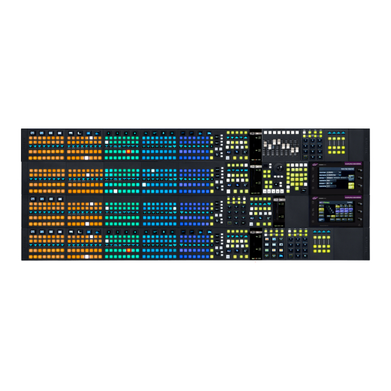
Summary of Contents for GRASS VALLEY KAHUNA Series
- Page 1 KAHUNA PRODUCTION SWITCHER Installation Manual 13-06514-040 2020-12-11...
-
Page 2: Fcc Compliance
USA, LLC, or one of its affiliates or subsidiaries. All other intellectual property rights are owned by GVBB Holdings SARL, Grass Valley USA, LLC, or one of its affiliates or subsidiaries. All third party intellectual property rights (including logos or icons) remain the property of their respective owners. - Page 3 The presence of this symbol in or on Grass Valley equipment means that it has been tested and certified as complying with applicable Underwriters Laboratory (UL) regulations and recommendations for USA.
- Page 4 Notices The presence of this symbol in or on Grass Valley product means that it complies with all applicable European Union (CE) directives. The presence of this symbol in or on Grass Valley product means that it complies with safety of laser product applicable standards.
- Page 5 Replace the battery only with the same or equivalent type recommended by the manufacturer. Dispose of used batteries according to the manufacturer’s instructions. Before disposing of your Grass Valley equipment, please review the Disposal and Recycling Information at: http://www.grassvalley.com/assets/media/5692/Take-Back_Instructions.pdf...
- Page 6 Notices Mesures de sécurité et avis importants La présente section fournit des consignes de sécurité importantes pour les opérateurs et le personnel de service. Des avertissements ou mises en garde spécifiques figurent dans le manuel, dans les sections où ils s’appliquent. Prenez le temps de bien lire les consignes et assurez-vous de les respecter, en particulier celles qui sont destinées à...
- Page 7 électrique, de compatibilité électromagnétique et de conformité environnementale. Le symbole ci-contre sur un appareil Grass Valley ou à l’intérieur de l’appareil indique qu’il est conforme aux normes applicables en matière de sécurité laser. Avertissements Les avertissements signalent des conditions ou des pratiques susceptibles d’occasionner des blessures graves, voire fatales.
- Page 8 Notices • Les produits qui n'ont pas d’interrupteur marche-arrêt et qui disposent d’une source d’alimentation externe doivent être installés à proximité d'une prise de courant facile d’accès. • Si l’équipement n’est pas pourvu d’un modules d’alimentation auto-adaptables, vérifiez la configuration de chacun des modules d'alimentation avant de les mettre sous tension. •...
- Page 9 Grass Valley believes this environmental information to be correct but cannot guarantee its completeness or accuracy since it is based on data received from sources outside our company. All specifications are subject to change without notice.
-
Page 10: Lithium Batteries
Lithium Batteries Battery Warning Your Grass Valley equipment usually comes with at least one button battery located on the main printed circuit board. The batteries are used for backup and should not need to be replaced during the lifetime of the equipment. -
Page 11: Laser Safety - Fiber Output Sfp And Qsfp Modules Warning
Kahuna Installation Manual Laser Safety - Fiber Output SFP and QSFP Modules Warning LASER SAFETY The average optical output power does not exceed 0 dBm (1mW) under normal operating conditions. Unused optical outputs should be covered to prevent direct exposure to the laser beam. -
Page 12: Mainframe Mains Supply Voltage
Notices Mainframe Mains Supply Voltage Before connecting the equipment, observe the safety warnings section and ensure that the local mains supply is within the rating stated on the rear of the equipment. Mains Inputs to the Kahuna 9600 - 11RU Mainframe Mains Inputs to the Kahuna 6400 - 6RU Mainframe Mains Input to Kahuna 9600 and Kahuna 6400 Mainframes To 11RU Mainframe PSU (RMY5 PSU4)100-240V at 50 and 60Hz... -
Page 13: Safety And Emc Standards
Kahuna Installation Manual Safety and EMC Standards This equipment complies with the following standards: Safety Standards Information Technology Equipment - Safety Part 1 EN60950-1: 2006 Safety of Information Technology Equipment Including Electrical Business Equipment. UL1419 (4 Edition) Standard for Safety – Professional Video and Audio equipment (UL file number E193966) EMC Standards This unit conforms to the following standards: EN55032:2015 (Class A) -
Page 14: Emc Performance Of Cables And Connectors
EMC Performance of Cables and Connectors Grass Valley products are designed to meet or exceed the requirements of the appropriate European EMC standards. In order to achieve this performance in real installations it is essential to use cables and connectors with good EMC characteristics. -
Page 15: Table Of Contents
Table of Contents FCC Compliance ..............ii Patent Information . - Page 16 Table of Contents Desk Mount..............24 Half 19"...
- Page 17 Kahuna Installation Manual Kahuna 9600 11RU Mainframe ..........71 Checking the Kahuna 9600 11RU Power Supplies.
- Page 18 Table of Contents...
-
Page 19: About This Manual
Kahuna Maverik is manufactured to Grass valley’s usual very high standard of build quality. It is designed to work with, control and complement the market leading Kahuna 9600 and Kahuna 6400 production switcher mainframes, giving the operator a level of unrivalled flexibility. - Page 20 About this Manual Introduction...
-
Page 21: Product Information
Carefully unpack the system components and check them against the packing list. • If there is anything incorrect notify your Grass Valley Partner, or Grass Valley, at once. • Check that the equipment has not been damaged in transit. If any damage has occurred notify your Grass Valley Partner (or Grass Valley directly) and the carrier immediately.... -
Page 22: What Is Supplied With The Mainframe
Product Information On Receipt of the Kahuna Maverik Control Surface • Box containing the User Manual and full Installation Manual What is supplied with the Mainframe Mainframe 11RU Kahuna 9600 or 6RU Kahuna 6400 • (customer order dependent). • 4x or 2x Mains Power Leads for the Mainframe (mainframe dependent). -
Page 23: Kahuna Maverik Order Codes
Kahuna Installation Manual Kahuna Maverik Order Codes Pre Configured Maverik Panels Ordering Information Part Number Description Maverik 1 ME Panel with 16 buttons - Includes: MAV-PNL-100-16 1x MAV-GUI, 1x MAV-8XPT-DEL-FS, 1x MAV-8XPT-FS, 1x MAV-TRANS, 1x MAV-KEYER, 1x MAV-UFBPAD, 1x MAV-JOY, 1x MAV-KEYPAD, 1x MAV-BP-40. - Page 24 Product Information Kahuna Maverik Order Codes Maverik 3 ME Panel with 24 buttons - Includes: MAV-PNL-300-24-1G 1x MAV-GUI, 3x MAV-8XPT-DEL-FS, 6x MAV-8XPT-FS, 3x MAV-TRANS, 1x MAV-KEYER, 1x MAV-UFBPAD, 1x MAV-JOY, 1x MAV-KEYPAD, 1x MAV-BP-40, 1x MAV-BP-60 NOTE- Must order separately :3x MAV - RowFrame - 940 - MAV-PNL- ROW-940 Maverik 3 ME Panel with 24 buttons - Includes: MAV-PNL-300-24-2G...
- Page 25 Kahuna Installation Manual Maverik 3 ME Panel with 32 buttons - Includes: MAV-PNL-400-32 2x MAV-GUI 3x MAV-8XPT-DEL-FS 9x MAV-8XPT-FS 3x MAV-TRANS 1x MAV-KEYER 3x MAV-UFBPAD 1x MAV-JOY 1x MAV-KEYPAD 1x MAV-DSK 1x MAV-BP-60 NOTE- Must order separately :3x MAV - RowFrame - 1260 - MAV-PNL- ROW-1260 Maverik 4 ME Panel with 40 buttons - Includes MAV-PNL-400-40...
-
Page 26: Mav Module Order Codes
Product Information Kahuna Maverik Order Codes MAV Module Order Codes Ordering Information MAV Module MAV Name/Part Number Description Width MAV-GUI MAV Touch screen GUI 220 mm interface Module with dual 8.66 Inches redundant external PSUs and comms to the mainframe. Power and control for up to 16 MAV modules. - Page 27 Kahuna Installation Manual Kahuna Maverik Ordering Information - continued MAV Module MAV Name/Part Number Description Width MAV-8XPT-OB Maverik 8-crosspoint Source 160 mm select Module with 6.29 Inches programmable OLED buttons. MAV-8XPT-FS Maverik 8-crosspoint Source 160 mm select Module. No 6.29 Inches programmable OLED buttons MAV-DSK Maverik Downstream Keyer...
- Page 28 Product Information Kahuna Maverik Order Codes Kahuna Maverik Ordering Information - continued Width MAV Module MAV Name/Part Number Description MAV-KEYPAD Maverik Numeric Keypad 100 mm Module for memories recall, 3.93 Inches Macros and clones enable, Live Mode set, plus Save Menu access.
-
Page 29: Mavrow Ears And Blanking Modules Order Codes
Kahuna Installation Manual Kahuna Maverik Ordering Information - continued Width MAV Module MAV Name Description MAV-AUD-FADER Maverik Audio Fader Module 160 mm with eight(8) motorized 6.29 Inches faders. Control specific functions of external audio mixers. MAVRow Ears and Blanking Modules Order Codes MAVRow Ears and 19”... - Page 30 Product Information Kahuna Maverik Order Codes The Blanking Modules fill the spaces in the control surface where MAV modules are not required, their function is aesthetic. Note: The widths of the blanking modules are in 20 mm (0.78 inch) increments, the smallest is 20mm (0.78 inch) up to 220 mm (8.66 inches). Blanking Module Ordering Information Part Number Description...
- Page 31 Kahuna Installation Manual MAV-BP 140 Maverik Module Blank 140mm Wide GV MAV-BP 160 Maverik Module Blank 160mm Wide GV MAV-BP 180 Maverik Module Blank 180mm Wide GV MAV-BP 200 Maverik Module Blank 200mm Wide GV MAV-BP 220 Maverik Module Blank 220mm Wide GV...
-
Page 32: Periodic Maintenance Of Mainframes
4 When finished, close the door and secure the door catch screw. Door Catch Screw 11RU Mainframe Mesh Door Filters 6RU Mainframe In the unlikely event of an equipment failure, contact the Grass Valley Customer Support Department, contact details are at the rear of this manual. -
Page 33: Environment And Location
Environment and Location Environmental Considerations The ambient temperature for all the supplied equipment should not exceed the limits of 5 and ° C (41 to 104F) at a relative humidity of 10 to 90% (non-condensing). Installing the equipment in a clean environment with moderate temperature and humidity will promote a long and trouble-free equipment life. -
Page 34: Mounting The Kahuna Maverik Control Surfaces Into A Desk
Environment and Location Mounting the Kahuna Maverik Control Surfaces into a Desk Mounting the Kahuna Maverik Control Surfaces into a Desk Note: Each MAVRow width and depth dimensions are unique to a customers requirements, please use the information below to calculate the dimensions of the control surface and the cut-out dimensions. -
Page 35: How To Calculate A Desk Cut-Out Width And Depth
Kahuna Installation Manual How to calculate a Desk Cut-out Width and Depth Note: The cutout has to be a minimum of 110mm (4.3 inches) into the desk to allow clearance for cables and airflow underneath the MAVRow frame. Cut-out Width - The calculation is:- Total Width MAV Modules and Blanking Modules in a row + 29 mm (1.14 in). -
Page 36: Optional Rebate In Desk
Environment and Location Mounting the Kahuna Maverik Control Surfaces into a Desk Optional Rebate in Desk The MAVRow frame can be rebated into the desk to make the Control Surface Flush with the surface of the desk. The Rebate has to be cut the entire way around the desk and cut to 5.9 mm (0.23 in). Rebate in Desk MAVRow Frame Desk... -
Page 37: Mounting A Mavrow Frame Into A Desk
Kahuna Installation Manual Mounting a MAVRow Frame into a Desk Note: The MAVRow frame should preferably be mounted in a desk which is open underneath. If the desk is not open underneath, enough room has to be left underneath for ventilation and for routing the PSU and Comms cables to the underside of the MAVRow frame.... -
Page 38: Mainframe Location And Environment
Environment and Location Mainframe Location and Environment Mainframe Location and Environment Location Instructions The Kahuna mainframes can be used freestanding (tabletop configuration) or installed in a standard 483mm (19 inch) equipment rack. The following precautions should be observed: The cooling fan exhausts at the rear of the unit must not be obstructed - a minimum clearance of 200mm (8 inches) is ESSENTIAL. -
Page 39: Kahuna 6400 6Ru Mainframe Air Flow
DAMAGE MAY RESULT. Depending on the length of time the mainframe has been run with no fan the unit may need to be returned for checking and repair. Contact Grass Valley or your Grass Valley dealer to discuss the situation. -
Page 40: Mounting The Kahuna 9600 11Ru Mainframe
Environment and Location Mounting the Kahuna 9600 11RU Mainframe Mounting the Kahuna 9600 11RU Mainframe Warning! Note: The Kahuna 9600 - 11RU Mainframe is extremely heavy (70kg – 155lb) and will require several people to lift into position using correct lifting procedures. -
Page 41: Mounting The Kahuna 6400 6Ru Mainframe
Kahuna Installation Manual Mounting the Kahuna 6400 6RU Mainframe Warning! Note: The Kahuna 6400 6RU Mainframe is very heavy (40kg – 88lb) and will require several people to lift into position using correct lifting procedures. If you are unsure of the lifting procedures, ask a Health and Safety adviser for information. -
Page 42: Mounting The Mav Remote
Environment and Location Mounting the Mav Remote Mounting the Mav Remote There are three ways to mount the Mav Remote: • Desk Mount • Half Rack Mount (with rack mount tray as support) • Rack Mount using 2x Mav Remote units with a joining plate Desk Mount The rack mount ear mounting brackets can be set to two different positions, horizontal with the mounting holes facing upwards, and vertically (for Rack Mount as described in the 19""Rack... -
Page 43: 19" Rack Mount Using Two Mav Remote Units With A Joining Plate
Kahuna Installation Manual 19” Rack Mount using two Mav Remote units with a Joining Plate Two Mav Remote units can be joined together using a joining plate, which allows the units to span across the full width of the rack and fasten to the rack without the support of a rack tray. The units are joined using a “Joining Plate”... -
Page 44: Lcd And Led Aux Panel - 19" Rack Installation
Environment and Location LCD and LED Aux Panel - 19” Rack Installation LCD and LED Aux Panel - 19” Rack Installation The method of mounting the LCD and LED Aux Panels into a 19” rack is exactly the same for both Aux panels. -
Page 45: Cabling And Connections
Cabling and Connections Comms Cables for the MAV Modules Once the MAVRow frame or frames are mounted into the desk the next step is to place the Comms cables ready to connect up the MAV- GUI and the other MAV modules. For each MAV-GUI that is purchased, there are 16x RJ45 Comms cables supplied, these will in turn, support up to 16 MAV modules. - Page 46 Cabling and Connections Comms Cables for the MAV Modules Note: Ensure that there is sufficient cable length to connect the cables to the MAV modules before fitting the modules to the MAVRow rails. Unless there is good enough access to allow cables to be connected with the MAV modules in place.
-
Page 47: Mav-Gui And Mav Module Connections
Kahuna Installation Manual MAV-GUI and MAV Module Connections MAV-GUI Connections The MAV-GUI is the most important module in the control surface, they provide power and Comms to all the other MAV modules and network connection to the Production Switcher mainframe. •... -
Page 48: Mav-Gui Connections - Continued
Cabling and Connections MAV-GUI and MAV Module Connections MAV-GUI Connections - continued Diagram below shows the connector information for the MAV-GUI MAV-GUI Connectors Connector Description PSU Connectors - Kycon KPPX 4Pin or Compatible 12V DC 8.33A Monitor Output 2x USB 2 Connectors 10/100/1000 base T, RJ45 network connectors to the switcher mainframe Connection to other MAV modules These are NOT Ethernet, connections must be direct to MAV modules. -
Page 49: Connecting A Touch Screen Monitor
Kahuna Installation Manual Connecting a Touch Screen Monitor The MAV-GUI has a “monitor” output port on its underside near the USB ports, the monitor port can be used to connect to an external “computer” touch screen or normal display monitor. The external monitor will have to have a 1920 x 1080 display resolution and it is recommended that the monitor be larger than 21 inches. -
Page 50: Mav Module Connections
Cabling and Connections Connecting a Touch Screen Monitor MAV Module Connections Even though the MAV-GUI has only 8 Comms ports, up to 16 MAV modules can actually be powered and controlled from one MAV-GUI. This is because each individual MAV has 2 Comms ports;... -
Page 51: Connection Diagram Example
Kahuna Installation Manual Connection Diagram Example he diagram below shows an example how a MAV-GUI can connect to 16 individual MAV modules... -
Page 52: Mav Remote Connections
Mav Remote Connections The Mav Remote is a rack mountable/desk top hardware element that provides a means of control to the Grass Valley switcher range. Essentially the Mav Remote enables control of the video hardware from a remote location away from the main control surface. -
Page 53: Mav Remote Connections - Continued
Kahuna Installation Manual Mav Remote Connections - continued Diagram below shows the connector information for the Mav Remote Mav Remote Connectors Connector Description PSU Connectors - Kycon KPPX 4Pin or Compatible 12V DC 8.33A Monitor Output 2x USB 2 Connectors 10/100/1000 base T, RJ45 network connectors to the switcher mainframe Connection to other MAV modules NOT Ethernet, connections must be direct to MAV modules. -
Page 54: Connecting A Touch Screen Monitor To The Mav Remote
Cabling and Connections Mav Remote Connections Connecting a Touch Screen Monitor to the Mav Remote The Mav Remote monitor port can be used to connect to an external “computer” touch screen or normal display monitor. The external monitor will have to have a 1920 x 1080 display resolution and it is recommended that the monitor be larger than 21 inches. -
Page 55: Mainframe Layout And Connections
Kahuna Installation Manual Mainframe Layout and Connections Mainframe Overview The Kahuna 9600 mainframe has completely new architecture that provides the building blocks for Inputs, Outputs, Mix Effects and DVE’s to build a production switcher to meet any requirement. Kahuna 9600 is designed for flexibility, easy configuration and an easy field upgradable solution. -
Page 56: 6Ru Mainframe Front Card Locations
Cabling and Connections 6RU Mainframe Front Card Locations 6RU Mainframe Front Card Locations 6RU Mainframe Card Locations Card Type Card Function Output Card Router Card M/E or DVE Cards... -
Page 57: 11Ru Mainframe Rear Fin Locations And Connectors
Kahuna Installation Manual 11RU Mainframe Rear Fin Locations and Connectors The table below outlines a fully populated mainframe. 11RU Mainframe Fins and Connectors Fin/Connector Description Connector Information Output Fin Fin O/P A Fin O/P A - 16x SDI BNC (numbered BNC 1 to 16) Fin O/P B Fin O/P B - 16x SDI BNC (numbered BNC 1 to 16) Network Fin... - Page 58 Each Input Fin has 6x SFP Cages (12 Inputs) Each Input Fin has 1x 25 Way D-type GPO Tally connector. SFP’s can be purchased as an options from Grass Valley. Signals supported over RTP stream per input Fin Module. ...
- Page 59 SFP (emSFP) optical, transceiver, medium haul, MSA, 1310nm" to the UHDI SFP list A single Fin has 3x SDI inputs, or 3x Fiber SFP inputs. SFP’s can be purchased as an options from Grass Valley. Reference Fin 6x Reference and Sync inputs/outputs...
- Page 60 Fin O/P C/D (supplied empty A single Fin has 4x SDISDI outputs, or 4x Fiber SFP outputs. with SFP options) SFP’s can be purchased as an options from Grass Valley. RS422 Control Ports 12x 9 Pin D-type connector RS422-R1-1 RS422-R1-12...
-
Page 61: 6Ru Mainframe Rear Fin Locations And Connectors
Kahuna Installation Manual 6RU Mainframe Rear Fin Locations and Connectors The table below outlines a fully populated mainframe. 6RU Mainframe Fins and Connectors Fin/Connector Description Connector Information Output Fin Fin O/P A Fin O/P A - 16x SDI BNC (numbered BNC 1 to 16) Fin O/P B Fin O/P B - 16x SDI BNC (numbered BNC 1 to 16) Optional ... - Page 62 MSA, 1310nm" to the UHDO SFP list (supplied empty A single Fin has 4x SDI outputs, or 4x Fiber SFP outputs. with SFP options) SFP’s can be purchased as an option from Grass Valley. Network Fin 8x Neutrik 10/100/1000 base T Fin NET...
- Page 63 Kahuna Installation Manual 6RU Mainframe Fins and Connectors Fin/Connector Description Connector Information Optional The FDI Fiber Input Fins are able to take the following SFP Modules (not supplied): Fin IN A FDI Fiber Input Fins Input Fiber Optic SFP Module - Single Mode Dual Rx Module (wideband 1260nM - 1620nM) (Supplied with Fin IN E...
- Page 64 SFP (emSFP) optical, transceiver, medium haul, MSA, 1310nm" to the UHDI SFP list.. A single Fin has 3x SDI inputs, or 3x Fiber SFP inputs. SFP’s can be purchased as an option from Grass Valley. RS422 Control Ports 6x 9 Pin D-type connector...
-
Page 65: Mainframe Connections
Kahuna Installation Manual Mainframe Connections The Kahuna 9600 Mainframes have Ethernet, Serial, Tally & GPI I/O ports. The Ethernet ports are used for connection between the mainframe and the GUI, to connect to a network. Note: The following pages that describe the mainframe Fins are for the 11RU Mainframe (unless indicated otherwise). -
Page 66: Optional - Fdo Fiber Output Fin
Cabling and Connections Output Fins Optional - FDO Fiber Output Fin Each FDO Fiber Output Fin has 16x outputs, which comprise of: • 3x SFP Cages, each cage has 2x outputs • 10x HD-SDI BNC outputs The maximum number of outputs are, 64 Outputs in total (11RU Mainframe), 32 Outputs in total (6RU Mainframe) with all Output Fins installed. -
Page 67: Optional - 40Gbe Ipo40 (Ip Output) Fin
Kahuna Installation Manual Optional - 40GbE IPO40 (IP Output) Fin Signals supported over RTP stream per output Fin Module with 2 x 40GbE QSFP Cages. SMPTE 2022-6 Outputs - 12 x 1.485Gpbs Format Sources Outputs - 12 x 2.970Gpbs 1080p Format Sources VSF TR-03 (SMPTE 2110)... -
Page 68: 50Gbe Ipo50 Output Fin
Cabling and Connections Output Fins 50GbE IPO50 Output Fin Signals supported over RTP stream per output Fin Module with 2 x 50GbE QSFP Cages. SMPTE 2110-20 4x 12Gbps Format Sources (ST2110-20/30/40) SMPTE 2022-6 Outputs - 12x 1.485Gpbs Format Sources Outputs - 12x 2.970Gpbs 1080p Format Sources VSF TR-03 (SMPTE 2110)... -
Page 69: Optional - Uhdo (12Gbps Output) Fin
Kahuna Installation Manual Optional - UHDO (12Gbps Output) Fin Each UHDO Fin has 4x BNC and 4x SFP cages for outputs. Only the SDI or the SFP can be used for a single output, i.e O/P1, not both. The maximum number of outputs for Kahuna 9600 are: •... -
Page 70: Network Fin
Cabling and Connections Network Fin Network Fin Kahuna 9600 has 8 Neutrik RJ45 10/100/1000 base T network connectors on a single Network Fin, another 8 are available if a second (optional) Network Fin is fitted. Fin NET B Fin NET A Right Side Left Side RJ45 Network connector... -
Page 71: Reference Fin
Kahuna Installation Manual Reference Fin Fin REF A Fin REF B GPI 1 - 24 GPI 1 - 24 GPI 25 - 48 GPI 25 - 48 GPO 1 - 12 GPO 1 - 12 Reference Fin - Sync and Reference Input/Outputs The information below references the Sync and Reference inputs/outputs: S1 - this is Sync output 1: analogue sync output. -
Page 72: Reference Fin - General Purpose Inputs (Gpi) Via 25 Way D-Type
Cabling and Connections Reference Fin Reference Fin - General Purpose Inputs (GPI) via 25 way D-Type The Reference Fin has 48 general-purpose inputs (there are another 48 GPI’s if a second Reference Fin is fitted) The action of each of these inputs may be allocated by the user from a range of functions. -
Page 73: Reference Fin - Gpo/Tally Via 25 Way D-Type
Kahuna Installation Manual Reference Fin - GPO/TALLY via 25 way D-Type The Reference Fin has up to 24 GPO/Tally outputs. Each pair of GPO pins (for example Pin 1 & Pin 14) are connected to contacts of a solid-state relay rated at 60V DC or AC Peak, current rating 0.8A continuous DC or AC. -
Page 74: Input Fins
Cabling and Connections Input Fins Input Fins There are up to 120 inputs to the mainframe spread over 10 Input Fins. Fin IN A Fin IN B Fin IN C Fin IN D Fin IN E Fin IN F Fin IN G Fin IN H Fin IN I Fin IN J GPO/TALLY Input BNC Input BNC... -
Page 75: Input Fin - Gpo/Tally Via 25 Way D-Type
Kahuna Installation Manual Input Fin - GPO/TALLY via 25 way D-Type The are 24 GPO/Tally outputs per Input Fin. Each pair of GPO pins (for example Pin 1 & Pin 14) are connected to contacts of a solid-state relay rated at 60V DC or AC Peak, current rating 0.8A continuous DC or AC. There is no particular polarity requirement. -
Page 76: Optional - Fdi Fiber Input Fin
Cabling and Connections Input Fins Optional - FDI Fiber Input Fin Each Input FDI Fiber Input Fin has 12x inputs, which comprise of: • 6x SFP Cages, each cage has 2x Inputs • 1x 25 Way D-Type GOP/Tally connector The maximum number of inputs are, 120 Inputs in total (11RU Mainframe), 60 Inputs in total (6RU Mainframe) with all input Fins installed. -
Page 77: Optional - 40Gbe Ipi40 (Ip Input) Fin
Kahuna Installation Manual Optional - 40GbE IPI40 (IP Input) Fin Signals supported over RTP stream per input Fin Module. 2 x 40GbE QSFP Cages. SMPTE 2022-6 12 x 1.485Gpbs Format Sources 12 x 2.970Gpbs 1080p Format Sources VSF TR-03 (SMPTE 2110) 12 x 1.485Gpbs Format Sources... -
Page 78: 50Gbe Ipi50 Input Fin
Cabling and Connections Input Fins 50GbE IPI50 Input Fin Signals supported over RTP stream per input Fin Module. 2 x 50GbE QSFP Cages. SMPTE 2110-20 3x 12Gbps Format Sources (ST2110-20/30/40) SMPTE 2022-6 12x 1.485Gpbs Format Sources 12x 2.970Gpbs 1080p Format Sources VSF TR-03 (SMPTE 2110)... -
Page 79: Optional - Uhdi (12Gbps Input) Fin
Kahuna Installation Manual Optional - UHDI (12Gbps Input) Fin A single UHDI 12Gbps Fin has 3x Inputs and a single 25 Way Tally GPO connector. Inputs are selectable between SDI and SFP via a user menu. The maximum number of Inputs for Kahuna 9600 are: •... -
Page 80: Rs422 Port Configuration
Cabling and Connections RS422 Port Configuration RS422 Port Configuration There are twelve 9-way D-type connectors (11RU mainframe, 6 RS422 ports on a 6RU mainframe) which provide RS422 control. Serial Ports are RS422 ports and can be assigned with communications protocols to communicate with number of external devices. -
Page 81: Positioning The Mav And Blank Modules
Positioning the MAV and Blank Modules MAV Modules Kahuna Maverik is a completely modular control surface, this means that the user is able to change the layout of the control surface to suit any user preference or production environment. The MAV modules can be easily lifted out of the MAVRow frame and be placed in any configuration the user wishes. - Page 82 Positioning the MAV and Blank Modules MAV Modules Connect the comms cables to the MAV modules, then carefully place the MAV Locating Pegs (on the underside of the MAV) into the keyway holes and slide the MAV to the right until it is in the locked position.
-
Page 83: Blanking Modules
Kahuna Installation Manual Blanking Modules Blanking Modules are designed to fill in the empty spaces in a MAVRow where MAV modules are not required, they fit into the MAVRow frame in exactly the same way as fitting a MAV module (as mentioned on the previous page). The blanking modules have locating pegs which fit into the keyway holes and slide into a locked position.... -
Page 84: Mavrow Ears
Positioning the MAV and Blank Modules MAV Modules MAVRow Ears There are two MAVRow Ears are supplied with every MAVRow, they are aesthetic and designed to cover the bare ends of the MAVRow frame. Note: Before fitting the MAVRow Ears, please read the safety information on “Use of Magnets with Maverik”... -
Page 85: Power Supplies
Power Supplies MAV-GUI External Power Supplies Each MAV-GUI that is purchased is supplied with 2 external 12V power supplies. One of the power supplies powers the MAV-GUI, the other is for redundancy. The Power Supplies have NO user serviceable parts inside and are welded shut. Do not attempt to open the power supply cases. - Page 86 Note: On the under side of the MAV-GUI is a PSU polarity setting screw. This is factory set to the supplied Grass Valley PSU polarity. There should be no attempt made to change the polarity by the customer. For further information please contact your Grass Valley Partner or Grass Valley Customer Support.
-
Page 87: Mav Remote External Power Supplies
Kahuna Installation Manual Mav Remote External Power Supplies The MAV Remote is supplied with 2 external 12V power supplies. One of the power supplies powers the Mav Remote, the other is for redundancy. The Power Supplies have NO user serviceable parts inside and are welded shut. Do not attempt to open the power supply cases.... -
Page 88: Mainframe Power Supplies
Power Supplies Mainframe Power Supplies Mainframe Power Supplies The information below gives an overview of all the power supplies used in the Kahuna 9600 and Kahuna 6400 mainframes. Caution Note: To reduce the risk of electric shock, plug each power supply cord into separate branch circuits employing separate service grounds. -
Page 89: Powering Up The Mainframes
Kahuna Installation Manual Powering Up the Mainframes Kahuna 9600 11RU Mainframe This symbol indicates that hazardous voltages are present inside. No User Serviceable Parts inside the power supplies. This unit should only be serviced by trained personnel. The power supplies for the Kahuna 9600 11RU mainframe are retained within the mainframe body, there are no On/Off switches for the power supplies. -
Page 90: Removing The Mainframe Power Supplies
Power Supplies Powering Up the Mainframes Removing the Mainframe Power Supplies The power supplies are held in place with a locking handle, which is in turn held in place by a sprung lever. Locking Handle Sprung Lever Press down on the sprung lever and lift the locking handle To remove a power supply from the mainframe chassis, press down on the sprung lever, and whilst holding it down, lift the locking handle on the power supply to the horizontal... -
Page 91: Kahuna 6400 6Ru Mainframe
Kahuna Installation Manual Kahuna 6400 6RU Mainframe Hazardous voltages are present inside. No User Serviceable Parts inside the power supplies. This unit should only be serviced by trained personnel. The power supplies for the Kahuna 6400 6RU mainframe are retained within the mainframe body, there are no On/Off switches for the power supplies. -
Page 92: Replacing The Power Supply
Power Supplies Kahuna 6400 6RU Mainframe Replacing the Power Supply With the locking handles in the open position, carefully slide the power supply sled along the rails until the sled stops. Do not force the sled, the locking handles will fully locate the PSU. -
Page 93: Dimensions
Dimensions MAVRow Diagram shows the end view of a MAVRow MAVRow Depth 140 mm ~ 5.51 Inches Height 70.4 mm ~ 2.77 Inches (surface of MAV-GUI to the bottom of the body) Weight Approx - TBC... - Page 94 Dimensions MAVRow Diagram showing a MAVRow end with a MAV-GUI fitted into the MAVRow IMPORTANT! When mounting a MAVRow frame into a desk, the cutout has to be a minimum of 110mm (4.3 inches) into the desk to allow clearance for cables and airflow underneath the MAVRow...
-
Page 95: Mav-Gui
Kahuna Installation Manual MAV-GUI MAV-GUI Width 220 mm ~ 8.66 Inches Depth 140 mm ~ 5.51 Inches Height 89.4 mm ~ 3.51 Inches (surface of MAV-GUI to the bottom of the body) (Top of the Rotary Knob to the bottom of the body = 111.1 mm ~ 4.37 Inches) Weight Approx - 1.6kg ~ 3.52lb Environmental... -
Page 96: Mav-Trans
Dimensions MAV-GUI MAV-Trans MAV-Trans Width 160 mm ~ 8.66 Inches Depth 140 mm ~ 5.51 Inches Height 58.9 mm ~ 2.31 Inches (surface of MAV-Trans to the bottom of the body) (Top of TBar to the bottom of the body = 104.3 mm ~ 4.10 Inches) Weight Approx - 746g ~ 1.64lb Environmental... -
Page 97: Mav-8Xpt-Del-Ob And Mav-8Xpt-Del-Fs
Kahuna Installation Manual MAV-8Xpt-Del-OB and MAV-8Xpt-Del-FS The diagram below shows the “MAV-8Xpt-Del-OB” module only, the dimensions of the “MAV- 8Xpt-Del-FS” module are exactly the same, please use the dimensions listed below for this MAV module. MAV-8Xpt-Del-OB and MAV-8Xpt-Del-FS Width 200 mm ~ 7.87 Inches Depth 140 mm ~ 5.51 Inches... -
Page 98: Mav-8Xpt-Fs And Mav-8Xpt-Ob
Dimensions MAV-GUI MAV-8Xpt-FS and MAV-8Xpt-OB The diagram below shows the “MAV-8Xpt-FS” module only, the dimensions of the “MAV-8Xpt- OB” module are exactly the same, please use the dimensions listed below for this MAV module. MAV-8Xpt-FS and MAV-8Xpt-OB Width 160 mm ~ 8.66 Inches Depth 140 mm ~ 5.51 Inches... -
Page 99: Mav-Dsk
Kahuna Installation Manual MAV-DSK MAV-DSK Width 100 mm ~ 3.93 Inches Depth 140 mm ~ 5.51 Inches Height 58.9 mm ~ 2.31 Inches (surface of MAV-DSK to the bottom of the body) Weight Approx - 360g ~ 12.69oz Environmental 41 to 104°F ~ 5 to 40°C non-condensing... -
Page 100: Mav-Joy
Dimensions MAV-GUI MAV-JOY MAV-JOY Width 100 mm ~ 3.93 Inches Depth 140 mm ~ 5.51 Inches Height 58.9 mm ~ 2.31 Inches (surface of MAV-DSK to the bottom of the body) Weight Approx - 500g ~ 1.10lb Environmental 41 to 104°F ~ 5 to 40°C non-condensing... -
Page 101: Mav-Keypad
Kahuna Installation Manual MAV-KEYPAD MAV-KEYPAD Width 100 mm ~ 3.93 Inches Depth 140 mm ~ 5.51 Inches Height 58.9 mm ~ 2.31 Inches (surface of MAV-KEYPAD to the bottom of the body) Weight Approx - 396g ~ 13.96oz Environmental 41 to 104°F ~ 5 to 40°C non-condensing... -
Page 102: Mav-Ufbpad
Dimensions MAV-GUI MAV-UFBPAD MAV-UFBPAD Width 100 mm ~ 3.93 Inches Depth 140 mm ~ 5.51 Inches Height 58.9 mm ~ 2.31 Inches (surface of MAV-UFBPAD to the bottom of the body) Weight Approx - 386g ~ 13.61oz Environmental 41 to 104°F ~ 5 to 40°C non-condensing... -
Page 103: Mav-Aud-Fader
Kahuna Installation Manual MAV-AUD-FADER MAV-AUD-FADER Width 160 mm ~ 6.29 Inches Depth 140 mm ~ 5.51 Inches Height 58.9 mm ~ 2.31 Inches (surface of MAV-AUD-FADER to the bottom of the body) Weight Approx - 900g ~ 31.74oz Environmental 41 to 104°F ~ 5 to 40°C non-condensing... -
Page 104: Mav-Auto
Dimensions MAV-GUI MAV-AUTO MAV-AUTO Width 160 mm ~ 6.29 Inches Depth 140 mm ~ 5.51 Inches Height 58.9 mm ~ 2.31 Inches (surface of MAV-AUTO to the bottom of the body) Weight Approx - 640g ~ 22.57oz Environmental 41 to 104°F ~ 5 to 40°C non-condensing... -
Page 105: Mav-Aux
Kahuna Installation Manual MAV-AUX MAV-AUX Width 160 mm ~ 6.29 Inches Depth 140 mm ~ 5.51 Inches Height 58.9 mm ~ 2.31 Inches (surface of MAV-AUX to the bottom of the body) Weight Approx - 640g ~ 22.57oz Environmental 41 to 104°F ~ 5 to 40°C non-condensing... -
Page 106: Mav-Keyer
Dimensions MAV-GUI MAV-KEYER MAV-KEYER Width 160 mm ~ 6.29 Inches Depth 140 mm ~ 5.51 Inches Height 58.9 mm ~ 2.31 Inches (surface of MAV-KEYER to the bottom of the body) Weight Approx - 760g ~ 26.80oz Environmental 41 to 104°F ~ 5 to 40°C non-condensing... -
Page 107: Mav Remote Dimensions
Kahuna Installation Manual Mav Remote Dimensions Mav Remote Dimensions Width 9.44 inches ~ 239.9 mm Depth 12.95 inches ~ 329 mm Height 2.00 inches ~ 50.7 mm (including feet) Weight TBC lbs ~ TBCkg Environmental 41 to 104°F ~ 5 to 40°C non-condensing... -
Page 108: Kahuna 9600 11Ru Mainframe Dimensions
Dimensions Kahuna 9600 11RU Mainframe Dimensions Kahuna 9600 11RU Mainframe Dimensions 11RU Mainframe Dimensions Width 19.07 inches ~ 484.5 mm including brackets Depth 19.21 inches ~ 488 mm Height 25.39 inches ~ 644.7 mm including connectors, PSU fans and door handle Weight 154.3 lbs ~ 70 kg... -
Page 109: Kahuna 6400 6Ru Mainframe Dimensions
Kahuna Installation Manual Kahuna 6400 6RU Mainframe Dimensions 6RU Mainframe Dimensions Width 19.07 inches ~ 484.5 mm including brackets Depth 10.47 inches ~ 266 mm Height 24.81 inches ~ 630.1 mm including connectors, PSU fans and door handle Weight 88.1 lbs ~ 40 kg Environmental 41 to 104°F... -
Page 110: Lcd And Led Aux Panel Dimensions
Dimensions Kahuna 6400 6RU Mainframe Dimensions LCD and LED Aux Panel Dimensions LCD and LED Aux Panel Dimensions Width 19 inches ~ 482.6mm Depth 1.51 inches ~ 38.4mm Height 1.72 inches ~ 43.6 mm Weight 2.2 lbs ~ 1kg Environmental 41 to 104°F ~ 5 to 40°C non-condensing Note: The diagram above displays the LCD Aux Panel dimensions. -
Page 111: Specifications
Specifications Kahuna Maverik Specifications MAV-GUI Connector Description Power Supply 2x PSU Connectors - Kycon KPPX 4 Pin or Compatible 12V DC 8.33A Video Output 1x Monitor Output 2x USB 2 Connectors Network 1x 10/100/1000 base T, Auto - MDX/MDXI on RJ45 connectors Connections to 8x RJ45 connectors for Comms and 2x +12V 0.42A power supply... -
Page 112: Kahuna 9600, Kahuna 6400 Mainframe Specifications
Specifications Kahuna 9600, Kahuna 6400 Mainframe Specifications Kahuna 9600, Kahuna 6400 Mainframe Specifications Television Standards 2.97Gbps Video Standards (1080p) 1080p 59.94Hz SMPTE-424M/Level A 1080p 59.94Hz SMPTE-424M/Level B 1080p 60Hz SMPTE-424M/Level A 1080p 60Hz SMPTE-424M/Level B ... - Page 113 Kahuna Installation Manual Mainframe Output Fins Outputs 11RU Mainframe 64 x 1080p-SDI/HD-SDI/SD-SDI Grouped in 16 off. SD/HD/1080p (270Mbps / 1.485Gbps / 2.97Gbps) 6RU Mainframe 32x 1080p-SDI/HD-SDI/SD-SDI Grouped in 16 off. SD/HD/1080p (270Mbps / (Optional) FDO 1.485Gbps / 2.97Gbps) Fiber Fin 16 outputs over 3x SFP Cages and 10x HD-SDI BNC's ...
- Page 114 Specifications Kahuna 9600, Kahuna 6400 Mainframe Specifications Mainframe Output Fin Formats & Levels (Optional) UHDO 4x UHD BNCs SMPTE ST 2082-10 12Gbps 4x SFP + complaint cages Output Fin 11.88Gbps Video Standards (UHD) SDI Output Tri Standard 3Gbps-SDI/HD-SDI/SD-SDI Grouped in 16 off. SD/HD/1080p Format (270Mbps / 1.485Gbps / 2.97Gbps) Analogue Sync...
- Page 115 Kahuna Installation Manual Mainframe Input Fins Number of Video Inputs 11RU Mainframe 120 x Tri standard, SD-SDI/HD-SDI/3Gbps-SDI (depending on options) each on 1x BNC 6RU Mainframe 60 x Tri standard, SD-SDI/HD-SDI/3Gbps-SDI (depending on options) each on 1x BNC (If all Input Fins are fitted)...
- Page 116 Specifications Kahuna 9600, Kahuna 6400 Mainframe Specifications Mainframe Input Fin Formats & Levels (Optional) UHDI 3x UHD BNCs SMPTE ST 2082-10 12Gbps 3x SFP + complaint cages Input Fin 11.88Gbps Video Standards (UHD) GPO (Tally) 1 x 25 Way D-type GPO Tally on each Input Fin with isolated contact closures. outputs (10 x 25 Way D-type GPO Tally connectors if all Input Fins are fitted) Mainframe...
-
Page 117: Mav Remote Specifications
Kahuna Installation Manual Mainframe Power Supplies Mainframes 11RU Mainframe Two fully independent hot-swappable PSU modules, with separate mains power feeds via 2 x 16A IEC-C20 socket. Dual Redundant requires two more fully independent PSU modules; with separate mains power feeds via 2 x 16A IEC ... - Page 118 Specifications Mav Remote Specifications...
-
Page 119: Contact Us
1-800-547-8949 (US and Canada) or +1 530 478 4148. To obtain a local phone number for the support center nearest you, please consult the Contact Us section of Grass Valley’s website ( www.grassvalley.com An online form for e-mail contact is also available from the website.
Need help?
Do you have a question about the KAHUNA Series and is the answer not in the manual?
Questions and answers