Table of Contents
Advertisement
Quick Links
Advertisement
Table of Contents

Related Manuals for Kirisun PT558


Summary of Contents for Kirisun PT558
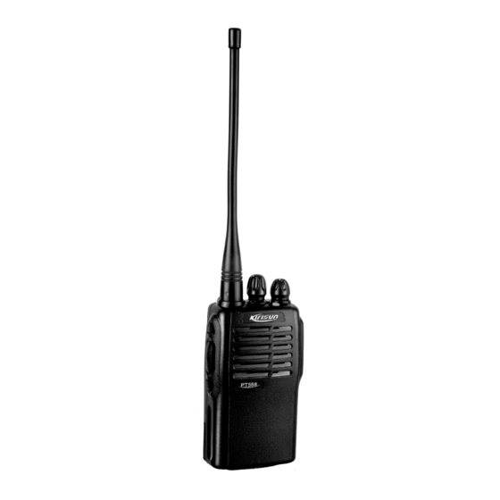
- Page 1 PROFESSIONAL TWO-WAY RADIO PT558 FM PORTABLE RADIO SERVICE MANUAL V060802...
-
Page 2: Table Of Contents
Appendix 5 Accessory List Kirisun Electronic (Shenzhen) Co., Ltd owns the copyright of the MCU software..22 Figure 1 PT558 Top Board Position Mark Diagram Kirisun Electronic (Shenzhen) Co., Ltd owns the copyright of the radio outward/structure/circuit design..23 Figure 2 PT558 Bottom Board Position Mark Diagram Kirisun Electronic (Shenzhen) Co., Ltd owns the... -
Page 3: Chapter 1 Introduction
Product serial number has been damaged or the product 1.1 Introduction trademark is difficult to identify. This manual applies to the service and maintenance of PT558 After the warranty expires, lifetime service is still available. And series of FM mobile radios, and is designed for the engineers and we also provide service components to service stations. -
Page 4: Chapter 3 Electrocircuit
PT558 SERVICE MANUAL Chapter 3 Electrocircuit IC5 inner circuit and X3 (49.5MHz) compose the 2nd local oscillator. The 2nd local oscillation (49.5MHz) and the 1st IF signal 3.1 Frequency Configuration (49.95MHz) are mixed at IC5 to generate the 2nd IF 450MHz . - Page 5 PT558 SERVICE MANUAL CTCSS Signal Filtering amplified, the amplitude of them is limited, and are filtered, they are sent to VCO together with CTCSS/DCS for modulation. The IC5 demodulated output audio signals may contain CTCSS (continuous tone coded squelch system) and DCS (digital coded D13, D308, and Q24 constitute AGC circuit which decreases squelch).
- Page 6 PT558 SERVICE MANUAL IC15 is a voice memory chip which stores the voice indication of Memorizer E PROM AT24C08 channels, and every time you change the channel, the speaker will Memorizes the radio channel data, CTCSS/DCS data, and sound voice annunciation of the current channel number. Press other data of function setting and parameter adjustment.
- Page 7 PT558 SERVICE MANUAL P21 I Encoding switch selection. -SEL DCS (digital code squelch) is a kind of continuous digital code Connect the pull down resistor with modulated with voice signals on carrier wave to control squelch. VSS . 83 groups of standard codes (positive and inverse code) are 7.3MHz Osc illator...
- Page 8 PT558 SERVICE MANUAL Table 3.5 Diode Function Description BUSY_V P61 Voice indication of circuit busy check DATA_V Voice indication data SCLK_V Voice indication clock Posi Type Function Description tion Not used MA77 Trans mitter an tenna s witch diode MA77...
-
Page 9: Chapter 4 Function Description And Parameter Setting
PT558 SERVICE MANUAL 4.1.2.3 Priority Channel Figure 3.8 Semiconductor Component Packaging Illustration: You can set one channel in the scanning list as the priority channel, which has the highest priority during scanning. The radio scans the first non-priority channel in the canning list and then scans the priority channel, the next non-priority channel in the scanning list, and then the priority channel again. - Page 10 PT558 SERVICE MANUAL conducted for over 10 seconds, the battery power saving will be a.Turn on the computer power. activated. When it is receiving signals or in operating state, battery b.Turn on the radio power. power saving is inactive. c.Click the KSP20 program to run the programming software.
-
Page 11: Chapter 5 Service Assemble And Disassemble
PT558 SERVICE MANUAL radio will not exit it automatically and you have to turn on the radio 5.2 Removing and Installing the Belt Clip again to enter the user's mode. Operating steps are as follows: To remove the belt clip, use your nail or a tool to lift the metal... - Page 12 PT558 SERVICE MANUAL 5.7 Exploded View 204-000558-R03 AL LABLE 301-20080G-R01 M2 SCREW MATERIAL NO. DECRIPTION MIC CAP 401-0201C1-R06 AL LABLE 202-000558-R09 MIC WASHER 204-000558-R02 WATERPROOF LABLE 204-006800-006 MIC COVER 301-25050J-R01 M2.5 SCREW 202-000558-R01 EMERGENCY BUTTON COVER PUSH FASTENER 201-000558-R08 201-000558-014...
-
Page 13: Chapter 6 Radio Debugging
PT558 SERVICE MANUAL Chapter 6 Radio Debugging 6.2 Debugging Items During the course of maintenance, the radio needs to be tested and debugged after replacing components. Some certain radio Before test/debugging, make sure all the equipments have parameters can be modified (computer mode) with our KSP 20 been well connected to the ground. - Page 14 PT558 SERVICE MANUAL potentiometer VR1, and watch the demodulation signals. The wave Item Test Test Test Adjustment Require Note shape should be smooth (close to square wave) and then adjust the -ment Condition Equipment Point Part figure to set the frequency deviation at 0.35kHz.
-
Page 15: Chapter 7 Major Specifications
PT558 SERVICE MANUAL Item Test Test Test Adjustment Require Note 4.0W @7.5V DC RF Power -ment Condition Equipment Point Part 2.5x10 Frequency Stability CTCSS CTCSS: Adjust Computer Frequency Anten 2.5kHz Maximum Modulation ± to 0.35kHz 67Hz Deviation ± 50Hz Test Mode... -
Page 16: Chapter 9 Kbc-58L Charger
PT558 SERVICE MANUAL PROBLEM SOLUTION A. The power amplifier tube Q11 is broken and indicator there is no power output and please change it with lights red a new tube. when in B. The microphone is broken, and please change it transmitti with a new one. -
Page 17: Appendix 2 Spare List
201-000558-R07 201-000558-R08 PT558 emergency button press panel/ PC+ABS,black,lead-free 201-000558-R09 PT558 light guide lens/ PMMA,transparent,lead-free PT558-03 front cover / PC+ABS,black,(to fix the 558 antenna), 060605 remould 201-005583-004 202-000558-R01 PT558 jack panel cover/ black silica gel(enhanced elasticity), hardness 70,lead-free 202-000558-R02 PT558PTT button / black silica gel,hardness 50,lead-free... -
Page 18: Appendix 4 Electrical Component List
202-000558-R04 PT558 switch waterproof washer / black silica gel,hardness 60,lead-free PT558 chassis waterproof gasket/ black silica gel,hardness 60,lead-free 202-000558-R06 PT558 big waterproof washer/ black silica gel enhanced elasticity ,hardness 202-000558-R07 40,lead-free PT558 positive/negative terminal spacer/ black silica gel,hardness 40,lead-free 202-000558-R08... - Page 19 PT558 SERVICE MANUAL 104-SC3356-R01 Chip triode / 2SC3356,lead-free 104-SC4617-R01 Chip triode / 2SC4617(S)(ROHM),lead-free Q6, Q9 104-SC4738-R01 Chip triode / 2SC4738(GR),AF,AMPLIFIER(TOSHIBA),lead-free 104-SC4919-R01 Chip triode / 2SC4919,MUTING,CIRCUIT(SANYO),lead-free 104-SC5108-R01 Chip triode / 2SC5108Y(TOSHIBA),lead-free Q2, Q4, Q5 104-TA1298-R01 Chip triode / KTA1298(Y),lead-free Q29, Q31, Q32...
- Page 20 PT558 SERVICE MANUAL 109-040683-R01 Chip resistor / 0402,68K 5%,lead-free R78, R245 109-040821-R01 Chip resistor / 0402,820R 5%,lead-free 109-040822-R01 Chip resistor / 0402,8.2K 5%,lead-free R229, R230 109-040823-R01 Chip resistor / 0402,82K 5%,lead-free 109-040913-R01 Chip resistor / 0402,91K 5%,lead-free R77, R213 109-060000-R01...
- Page 21 PT558 SERVICE MANUAL 112-043471-R01 Chip capacitor / 0402,470P 10%,50V,X7R,lead-free C4, C9, C22, C29,C48,C51,C52,C53,C54, C57, C58, C59,C60, C61,C71,C83,C84, C125, C152, C163,C248,C258,C269,C270,C274,C275, C290, C291,C305,C308,R161,R270,R271 C285 112-043472-R01 Chip capacitor / 0402,4700P 10%,25V,C0G,lead-free C212, C213, C253, C283 112-043473-R01 Chip capacitor / 0402,0.047uF 10%,16V,X7R,lead-free 112-043474-R01 Chip capacitor / 0402,0.47uF 10%,16V,X7R,lead-free...
- Page 22 3.5mm MIC socket / SP/MIC,ST-212,lead-free 124-050000-R04 2.5mm earphone socket / SP/MIC,EJ-2507-CCPA,lead-free 124-050000-R05 PT3208 PVC MIC spacer / transparent PVC,0.5MM thick 201-003208-029 PT558 speaker contact spring/ carbon spring wire 0.25,gilt 203-000558-004 378 crystal oscillator spacer/dobouble-faced adhesive sponge,5*5 204-000378-001 PT558 potentionmeter spacer / PVC transparent,self-adhesive, 0.35THK,lead-free...
-
Page 23: Appendix 5 Accessory List
PT558 SERVICE MANUAL Appendix 5 Accessory List Specification Accessory Figure Item Model Battery KB-58A 7.4V 1200mAh Li-Ion Hand Strap 8AJD-20K KME-201 Earphone KME-202 Charger KBC-58L 7-hour standard charger Adapter KTC-58C1 DC OUT 15V 400mA KA-3U057 Antenna KA-2U046... - Page 24 PT558 SERVICE MANUAL Figure 1 PT558 Top Board Position Mark Diagram...
- Page 25 PT558 SERVICE MANUAL Figure 2 PT558 Bottom Board Position Mark Diagram...
-
Page 26: Figur3 Pt558 Schematic Circuit Pane Diagram
Figur3 PT558 Schematic Circuit Pane Diagram... -
Page 27: Figur4 Pt558 Schematic Circuit Pane Diagram
Figur4 PT558 Schematic Circuit Pane Diagram 8 25... -
Page 28: Figure 5 Kbc-58L Schematic Circuit Diagram
Figure 5 KBC-58L Schematic Circuit Diagram KBC-58L Schematic Circuit Diagram 8 26...
Need help?
Do you have a question about the PT558 and is the answer not in the manual?
Questions and answers