
Related Manuals for Kirisun PT5200


Summary of Contents for Kirisun PT5200
- Page 1 PROFESSIONAL TWO-WAY RADIO PT5200 FM P RTABLE RADIO SERVICE MANUAL V070607 PDF created with pdfFactory Pro trial version www.pdffactory.com...
-
Page 2: Table Of Contents
Figure 5 KBC-42A Schematic Circuit Diagram ....26 performance. STATEMENT Kirisun Electronic (Shenzhen) Co., Ltd owns the copyright of KSP5200 software. Unauthorized Duplication of KSP5200 software is strictly prohibited. Kirisun Electronic (Shenzhen) Co., Ltd owns the copyright of the MCU software. -
Page 3: Chapter 1 Introduction
Introduction months. Accessories (such as battery pack, power adapter, antenna This manual applies to the service and maintenance of PT5200 or charger) are guaranteed for free service of 6 months. Earphones series of FM portable radios, and is designed for the engineers and are wearing parts and out of warranty. -
Page 4: Chapter 3 Electrocircuit
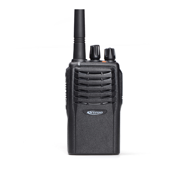
PT5200 SERVICE MANUAL ⑦ Top Button Pro grammable funct ion button: Press it to activate the IF Circuit programmable auxiliary function. The 1st IF signals from the crystal filter are amplified at the first IF ⑧ Microphone/Speaker Jacks amplifier (Q204), and then are sent to the IF processing IC (IC204, For connecting the optional Microphone/Speaker. - Page 5 PT5200 SERVICE MANUAL control. transmitter output power will decrease. Vice versa, such can ensure Ω Speaker Impedance: 16 steady transmitter output power in different working circumstances. Q405: Receiving Audio Signal Switch MCU changes the input power to IC3B to set the power.
- Page 6 PT5200 SERVICE MANUAL and are sent to VCO to change VCO oscillation frequency to the Checks the action of each function key preset value, and then VCO is locked. Generates content of voice indication N=FVCO/FR Generates Power-On Indication Tone :...
- Page 7 PT5200 SERVICE MANUAL CODIO AK2346 DIO input DCS (digital code squelch) is a kind of continuous digital code CTCOUT QT/DQT output modulated with voice signals on carrier wave to control squelch. PLL power save mode control 83 groups of standard codes (positive and inverse code) are available.
- Page 8 PT5200 SERVICE MANUAL 2SJ243 C5V switch Q503 NCON Narrow band RX control. H:effective in narrow 2SA1745 T5V witch Q502 band Q504 2SJ243 R5V switch : RX indicator control. H Light LEDR , DTC144EE Q405 Receiver audio output switch cut off :...
-
Page 9: Chapter 4 Function Description And Parameter Setting
PT5200 SERVICE MANUAL when the priority channel receives a signal the radio will Figure 3.8 Semiconductor Component Packaging automatically switch to the priority channel even the normal channel Illustration: is receiving signals at that time. And the radio will stay on the priority channel till that signal disappears. - Page 10 PT5200 SERVICE MANUAL 4.1.7 Monitor 4.1.12 Squelch Level Selection When no signals are being received, the radio squelch circuit mutes The purpose of the squelch is to mute the speaker noise when no the speaker. signals are received or the signals are weak. When the squelch is Press the MONI key to cut off the squelch control circuit, and you activated, you can hear noise from the speaker;...
-
Page 11: Chapter 5 Service Assemble And Disassemble
PT5200 SERVICE MANUAL it's prohibited to press the PTT button; when the radio is being Chapter 5 Service Assemble and Disassemble written data, the indicator lights red. 3) Before the first time editing, you should read data form the radio The radio is precision communication equipment. - Page 12 PT5200 SERVICE MANUAL 5.4 Exploded View 5.3 Removing the Casing from the Chassis Remove the knobs; Remove the two knob nuts and the antenna nut; MATER AL No . DECRIP TION Remove the two cross head screws that fix the top cover at...
- Page 13 Earphone rod bearing J401 201-000558-R09 PT558 Light guide lens 124-050000-R04 MIC rod bearing J402 201-005200-R02 PT5200 Front cover 604-052000-R01 PT5200 front cover components 202-000558-R03 PT558 Emergency Key 202-000558-R01 PT558 earphone/Mic cover 204-000558-R01 PT558 Speaker waterproof net 202-000668-R01 PT668PTT rubber key 204-006800-R06...
-
Page 14: Chapter 6 Radio Debugging
PT5200 SERVICE MANUAL 6.2 Debugging Items Chapter 6 Radio Debugging During the course of maintenance, the radio needs to be tested and debugged after replacing components. Some certain radio Before test/debugging, make sure all the equipments have been parameters can be modified (computer mode) with our KSP 5200 well connected to the ground. - Page 15 PT5200 SERVICE MANUAL ” “← →” Deviation (Narrow Band) and press Enter. Press key to “ ” ↓ “ ” Press on the keyboard to enter Medium Power (Low) make the DTMF Frequency Deviation at 1.5+/-0.1KHZ. “← →” and press Enter. Press key to make the TX power at 2+/- 0.2w and then press Enter to store the setting.
-
Page 16: Chapter 7 Technical Specifications
PT5200 SERVICE MANUAL frequency, SIAND is adjusted to 8dB. Press Enter to watch the RX 7.3 Transmitter sensitivity and press Enter to store the data after the value “ RF Power 4.0W @7.5V DC becomes steady. It's the same for SQL 1 OFF (Wide Band, ≤... -
Page 17: Chapter 9 Kbc-42A Charger
PT5200 SERVICE MANUAL Chapter 9 KBC-42A Charger Appendix 1 Abbreviations amplify, amplifier antenna 9.1 Charger Specifications automatic power control ≤ A) Idling Input Current: 15mA band pass filter ~ B) Charging Terminal Maximum Idling Voltage: 96% 97% of the CTCSS continuous tone control squelch system... -
Page 18: Appendix 3 Framework Component List
PT5200 SERVICE MANUAL Material Serial No. Name/Specification Position Note Earpiece-Mic jack panel cover black silica gel(enhanced elasticity) 202-000558-R01 hardness70 PTT keystroke black silica gel(enhanced elasticity) 202-000668-R01 Annunciator keystroke orange silica gel(enhanced elasticity) hardness60 202-000558-R03 Switch water-proof gasket black silica gel hardness60... - Page 19 PT5200 SERVICE MANUAL 104-TA1298-R01 Chip FET(field-effect transistor) / 2SJ243, Q721 105-2SJ243-R01 Q303, Q503, Q504 Chip FET(field-effect transistor) / 2SK508NV(K52), 105-2SK508-R01 Chip FET(field-effect transistor) / 3SK318, Q302, Q307 105-3SK318-R01 Chip FET(field-effect transistor) / RD01MUS1, Q21, Q26 105-RD01MU-R01 Chip FET(field-effect transistor) / RD07MVS1,...
- Page 20 PT5200 SERVICE MANUAL ± 109-040474-R01 Chip resistor / 0402,4.7R 5%, R602, R708, R710 ± 109-0404R7-R01 Chip resistor / 0402,51K 5%, R411, R412, R309 ± 109-040513-R01 Chip resistor / 0402,56R 5%, R479, R701, R410, R337 ± Chip resistor / 0402,560R 5%,...
- Page 21 PT5200 SERVICE MANUAL ± 112-043561-R01 Chip capacitor / 0402,560P 10%,16V,X7R, C477 ± 112-043562-R01 Chip capacitor / 0402,5600P 10%,16V,X7R, C460 ± Chip capacitor / 0402,5P 0.25P,50V,C0G, C360, C361 112-0435R0-R01 ± Chip capacitor / 0402,0.068uF 10%,16V,X7R, 112-043683-R01 C401, C446 ± 112-0437R0-R01 Chip capacitor / 0402,7P 0.5P,50V,C0G, C731, C105, C240, C257 ±...
-
Page 22: Appendix 4 Accessory List
PT5200 SERVICE MANUAL TH101, TH22 119-060473-R01 ± Hot quick resistor / NTH5G16P40B473J,47K 5%,0603, 121-200000-R01 Mic socket / B6027AP402-88(old Model:B6027AP402-65), X501 122-110M00-R01 Chip transistor / 10MHz,CSTCC10.0MG-TC,3*7mm, X301 122-112M80-R02 Chip transistor/ 12.8MHz,TCXO,DSA535SA, X402 , 122-23M686-R01 Plug-in crystal oscillator / 3.6864MHz J402 124-050000-R04 3.5mm Mic socket/ SP/MIC,ST-212,... -
Page 23: Figure1 Pt5200 Top Board Position Mark Diagram
PT5200 SERVICE MANUAL Figure 1 PT5200 Top Board Position Mark Diagram PDF created with pdfFactory Pro trial version www.pdffactory.com... -
Page 24: Figure2 Pt5200 Bottom Board Position Mark Diagram
PT5200 SERVICE MANUAL Figure 2 PT5200 Bottom Board Position Mark Diagram PDF created with pdfFactory Pro trial version www.pdffactory.com... -
Page 25: Figure 3 Pt5200 Schematic Circuit Pane Diagram
PT5200 SERVICE MANUAL Figure3 PT5200 Schematic Circuit Pane Diagram PDF created with pdfFactory Pro trial version www.pdffactory.com... -
Page 26: Figure 4 Pt5200 Schematic Circuit Pane Diagram
PT5200 SERVICE MANUAL Figure4 PT5200 Schematic Circuit Pane Diagram PDF created with pdfFactory Pro trial version www.pdffactory.com... -
Page 27: Figure 5 Kbc-42A Schematic Circuit Diagram
PT5200 SERVICE MANUAL Figure 5 KBC-42A Schematic Circuit Diagram PDF created with pdfFactory Pro trial version www.pdffactory.com...
Need help?
Do you have a question about the PT5200 and is the answer not in the manual?
Questions and answers