Table of Contents
Advertisement
Quick Links
Advertisement
Table of Contents

Related Manuals for CAB XD Q


Summary of Contents for CAB XD Q
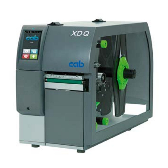
- Page 1 Instructions Label Printer XD Q MADE IN GERMANY...
- Page 2 Edition: 09/2022 - Part No. 9003776 Copyright This documentation as well as translation hereof are property of cab Produkttechnik GmbH & Co. KG. The replication, conversion, duplication or divulgement of the whole manual or parts of it for other intentions than its original intended purpose demand the previous written authorization by cab.
-
Page 3: Table Of Contents
Table of Contents Introduction ............................4 Instructions ............................... 4 Intended Use ............................4 Safety Instructions ............................ 5 Environment ............................. 5 Installation .............................. 6 Device Overview ............................6 Unpacking and Setting-up the Printer ...................... 8 Connecting the Device ..........................8 2.3.1 Connecting to the Power Supply ...................... -
Page 4: Introduction
Introduction Instructions Important information and instructions in this documentation are designated as follows: Danger! Draws attention to an exceptionally great, imminent danger to your health or life due to hazardous voltages. Danger! Draws attention to a danger with high risk which, if not avoided, may result in death or serious injury. Warning! Draws attention to a danger with medium risk which, if not avoided, may result in death or serious injury. -
Page 5: Safety Instructions
Introduction Safety Instructions The device is configured for voltages of 100 to 240 V AC. It only has to be plugged into a grounded socket. • • Only connect the device to other devices which have a protective low voltage. Switch off all affected devices (computer, printer, accessories) before connecting or disconnecting. -
Page 6: Installation
Installation Device Overview 1 LED "Power on" 2 Display 3 Peripheral connector 4 Flap 5 Cover 6 Inner margin stop 7 Outer margin stop 8 Roll retainer 9 Upper ribbon supply hub 10 Upper ribbon take-up hub 11 Print mechanics 12 Lower ribbon supply hub 13 Lower ribbon take-up hub Figure 1... - Page 7 Installation 15 Upper ribbon deflection 16 Printhead retainer with upper printhead 17 Pressing roller system 18 Pinch roller 19 Upper print roller 20 Upper guides 21 Tear-off plate 22 Detent pin 23 Guide roller 24 Label sensor 25 Allen key 26 Upper printhead locking lever 27 Knob for guide adjustment Figure 3...
-
Page 8: Unpacking And Setting-Up The Printer
Installation Unpacking and Setting-up the Printer Lift the label printer out of the box. Check label printer for damage which may have occurred during transport. Set up printer on a level surface. Remove foam transportation safeguards near the printhead. ... -
Page 9: Touchscreen Display
Touchscreen Display The user can control the operation of the printer with the control panel, for example: • Issuing, interrupting, continuing and canceling print jobs, Setting printing parameters, e.g. heat level of the printhead, print speed, interface configuration, language and •... - Page 10 Touchscreen Display With special software or hardware configurations additional symbols appear on the start screen: Printing on demand Printing on demand Direct cut without print job within print job with cutter installed Figure 7 Optional symbols on the start screen Release printing of a single label within a Release a direct cut without media feed print job including peeling-off, cutting...
-
Page 11: Navigation In The Menu
Touchscreen Display Navigation in the Menu Start level Selection level Parameter/function level Figure 9 Menu levels To open the menu select on the start screen. Select a theme in the selection level. Several themes have substructures again with selection levels. To return from the current level to the upper one select . -
Page 12: Loading Material
Loading Material Notice! For adjustments and simple installation work, use the accompanying Allen key located in the upper section of the print unit. No other tools are required for the work described here. Loading Media from Roll 4.1.1 Positioning the Media Roll on the Roll Retainer Figure 11 Loading media from roll 1. -
Page 13: Inserting Media Into The Print Mechanics
Loading Material 4.1.2 Inserting Media into the Print Mechanics Figure 12 Media feed path 1. Unroll a longer media strip of approx. 50 cm. Guide the media strip to the print mechanics as shown in Figure 12. 2. Pull the detent pin (6). The pressing roller system (1) will swing upwards. 3. -
Page 14: Setting The Label Sensor
Loading Material 4.1.3 Setting the Label Sensor Figure 14 Setting the label sensor The label sensor can be shifted perpendicular to the direction of paper flow for adaptation to the media. The sensor unit (2) of the label sensor is marked with an indentation in the label sensor retainer. When the printer is switched on, a yellow LED illuminates the sensor position. -
Page 15: Loading Transfer Ribbon
Loading Material Loading Transfer Ribbon Notice! With direct thermal printing, do not load a transfer ribbon; if one has already been loaded, remove it. Figure 17 Load transfer ribbon Figure 18 Transfer ribbon feed path 1. Clean the printheads before loading the transfer ribbon ( 6.3 on page 20). 2. -
Page 16: Setting The Feed Path Of The Transfer Ribbon
Loading Material Setting the Feed Path of the Transfer Ribbon Transfer ribbon wrinkling can lead to print image errors. Transfer ribbon deflection can be adjusted so as to prevent wrinkles. Notice! The adjustment is best carried out during printing. Figure 19 Setting the upper ribbon feed path Figure 20 Setting the lower ribbon feed path 1. -
Page 17: Operation
Operation Printhead Protection Attention! Printhead damage caused by improper handling! Do not touch the heating elements of the printheads with the fingers or sharp objects. Ensure that the material is clean. Ensure that the material surfaces are smooth. Rough material act like emery paper and reduce the service life of the printhead. -
Page 18: Avoiding Loss Of Material
Operation Avoiding Loss of Material Attention! Loss of material! The print images for the upper and the lower side of one label/section are printed at two different places in the media feed. Therefore every interruption of the continuos print process has the following consequences : •... -
Page 19: Avoiding Loss Of Data
Operation Avoiding Loss of Data Attention! Loss of data! When correctable errors occur labels/sections which are already printed by the lower printhead but not are completed by the upper printhead cannot be repeated after error correction. The data of those sections are lost for the printer. -
Page 20: Cleaning
Cleaning Cleaning Information Danger! Risk of death via electric shock! Disconnect the printer from the power supply before performing any maintenance work. The transfer printer requires very little maintenance. It is important to clean the thermal printheads regularly. This guarantees a consistently good printed image and plays a major part in preventing premature wear of the printhead. -
Page 21: Cleaning The Label Sensor
Cleaning Cleaning the Label Sensor Attention! Label sensor can be damaged! Do not use sharp or hard objects or solvents to clean the label sensor. The label sensor can become dirtied by paper dust. This can adversely affect label detection. Figure 21 Cleaning the label sensor 1. -
Page 22: Fault Correction
Fault Correction Error Display The appearance of an error will be shown on the display: Figure 22 Error display The error treatment is pending on the error type 7.2 on page 23. The display offers the following possibilities to continue after an error occurred: Repeat The print job will be continued after clearing the error cause. -
Page 23: Error Messages And Fault Correction
Fault Correction Error Messages and Fault Correction Error message Cause Remedy Barcode error Invalid barcode content, e.g. alphanumeric Correct the barcode content. characters in a numerical barcode Barcode too big The barcode is too big for the allocated Reduce the size of the barcode or move it. area of the label Check ribbon ink Identified ribbon unwinding direction does... - Page 24 Fault Correction Error message Cause Remedy Out of paper Out of label roll Load labels. Error in the paper feed Check paper feed. Pinch roller open The pressing roller system is not locked. Lock the pressing roller system. Read error Read error when reading from the memory Check data of the card.
-
Page 25: Problem Solution
Fault Correction Problem Solution Problem Cause Remedy Transfer ribbon deflection not adjusted Adjust the transfer ribbon deflection. Transfer ribbon creases 4.3 on page 16 Head locking system not adjusted Adjust the head locking system. 4.1.4 on page 14 Transfer ribbon too wide Use a transfer ribbon slightly wider than the width of label. -
Page 26: Media
Media Media Dimensions Figure 23 Media dimensions Dim. Designation Dim. in mm Label width 10 - 110 Label distance > 2 Media width Liner, continuos media 4 - 114 ≤ 114 Shrink tube, ready for use 4 - 85 Shrink tube, continuos, pressed ≥... -
Page 27: Device Dimensions
Media Device Dimensions Gap sensor & Reflective sensor Lower printhead Upper printhead Cut edge Figure 24 Device dimensions Dim. Designation Dim. in mm Distance printhead - cut edge with cutter CSQ 48,6 with stacker ST400 62,0 105,7 Print width Distance gap/reflective sensor - middle of paper track -53 - ±0 i.e. -
Page 28: Reflex Mark Dimensions
Media Reflex Mark Dimensions Figure 25 Reflex mark dimensions Dim. Designation Dim. in mm ≥ 20 Print zone height Print zone distance > 2 Feed length > 7 Width of reflex mark > 5 Height of reflex mark 3 - 10 -53 - ±0 Distance mark - middle of media track = Distance gap/reflective sensor - middle of media track... -
Page 29: Cut-Out Mark Dimensions
Media Cut-out Mark Dimensions Figure 26 Cut-out mark dimensions Dim. Designation Dim. in mm ≥ 20 Print zone height Print zone distance > 2 Feed length > 7 > 5 Width of cut-out Height of cut-out 2 - 10 -53 - ±0 Distance cut-out - middle of media track = Distance gap/reflective sensor - middle of media track Sensor recognized virtual print zone front edge with gap sensor recognition... -
Page 30: Licenses
Licenses Reference to the EU Declaration of Conformity The printers of the XD Q series comply with the relevant fundamental regulations of the EU Rules for Safety and Health: • Directive 2014/35/EU relating to electrical equipment designed for use within certain voltage limits •... -
Page 31: Index
Index Reflex marks........28 Cleaning Ribbon deflection, setting ....16 label sensor ........21 printhead ........20 Ribbon feed path, setting....16 print roller ........20 RS232 interface ........18 Cleaning information......20 Connecting .........8 Contents of delivery ......8 Safety instructions ......5 Cut-out marks ........29 Service work ........5 Cutting ..........19 Setting-up ...........8 Supply voltage ........8... - Page 32 This page was left blank intentionally.
Need help?
Do you have a question about the XD Q and is the answer not in the manual?
Questions and answers