Table of Contents
Advertisement
Advertisement
Table of Contents

Subscribe to Our Youtube Channel
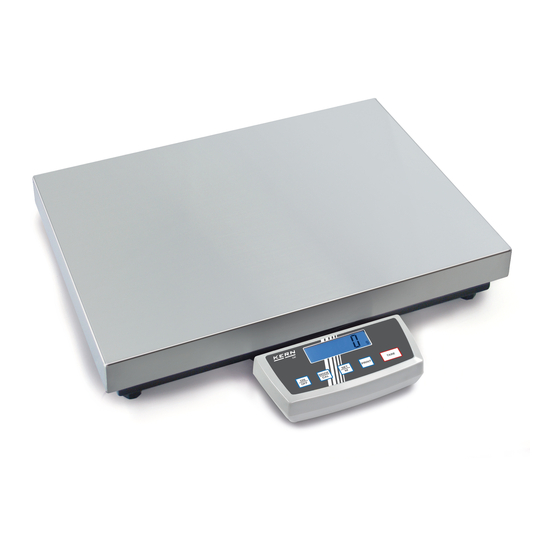
Summary of Contents for KERN KERN DE
- Page 1 KERN & Sohn GmbH D-72322 Balingen-Frommern Tel: 0049-[0]7433- 9933-0 Postbox 4052 Fax: 0049-[0]7433-9933-149 E-Mail: info@kern-sohn.de Internet: www.kern-sohn.de Service Manual Page 2 Electronic Precision Balances KERN DE version 1.1 06/01 DE-SH-e-0111...
-
Page 2: Table Of Contents
KERN DE version 1.1 06/01 Service Manual Electronic Precision Balances INTRODUCTION .....................3 Features......................3 Digital auto adjusting procedure..............3 Internal adjusting procedure ................4 Display segment test..................4 FUNCTIONAL BLOCK DIAGRAM / DESCRIPTION ..........5 Functional block diagram ................5 Function description ..................6 TROUBLESHOOTING ....................7 REPLACEMENT OF PCBA ..................8 Replacement of analogue PCBA ..............8... -
Page 3: Introduction
1 Introduction 1.1 Features • Full Tare • Memory function with indicator • Stable indicator • Negative value indication • Two types of Digital Auto Adjusting • Solder Pads to prevent end-user internal adjusting • Low battery indicator • Auto off function (battery mode only) •... -
Page 4: Internal Adjusting Procedure
1.3 Internal adjusting procedure 1. Remove the bottom housing of the remote display box. 2. Connect J2 on the display board (by soldering). 3. With platform empty, turn the balance on. The display should now zero with the unit indicator on. 4. -
Page 5: Functional Block Diagram / Description
2 Functional block diagram / description 2.1 Functional block diagram Ke yb o a rd LC D Po w e r c o ntr o l / 9 V Ba tte ry M i c ro - Re g u l a to r & Lo w b a tte ry p r o c e sso r A d a p te r... -
Page 6: Function Description
2.2 Function description 1. Load cell This is the heart of the whole system. Four load cells, located in the four corners of the platform, are arranged as a bridge. The resistance change of the bridge elements is proportional to the load applied on the load cells. Therefore the output of the load cells is an analogue signal, which is proportional to the load applied on the platform. -
Page 7: Troubleshooting
3 Troubleshooting Turn the balance on Full segments on the display ? If no display, check battery / adapter; connection between keyboard – display board, battery / adapter – display board. If some segments are missing, check fixing of the LCD frame, the zebra connector underneath the LCD. -
Page 8: Replacement Of Pcba
4 Replacement of PCBA 4.1 Replacement of analogue PCBA 1. Disassemble the stainless cover and the metal top housing from the platform. 2. Disconnect PL1 and PL2 from the analogue PCBA. Replace it by a new PCBA. Connect PL1 and PL2 again. Assemble the ground wire with a screw. 3. -
Page 9: Schematics
5 Schematics DE-SH-e-0111... - Page 10 DE-SH-e-0111...
- Page 11 DE-SH-e-0111...
- Page 12 DE-SH-e-0111...
-
Page 13: Spare Parts List
6 RDE-150-03-001 Overlay KERN DE150K50 7 RDE-150-03-0L1 Overlay KERN DE150K50L 8 RDE-300-03-001 Overlay KERN DE300K100 9 RDE-006-10-001 Display assy KERN DE 6K2 10 RDE-015-10-001 Display assy KERN DE 15K5 11 RDE-030-10-001 Display assy KERN DE 30K10 12 RDE-060-10-001 Display assy KERN DE60K20...


Need help?
Do you have a question about the KERN DE and is the answer not in the manual?
Questions and answers