
Related Manuals for Gasmate Nebula 6205


Summary of Contents for Gasmate Nebula 6205
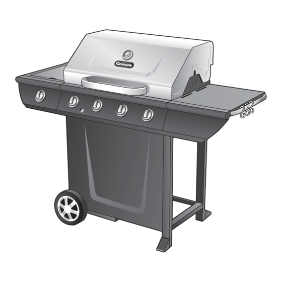
- Page 1 Nebula 6205 Gas Grill Model No. GM172-068 FOR OUTDOOR USE ONLY - OPERATES ON LPG 3419-05/12...
-
Page 2: General Information
GENERAL INFORMATION Gas Installation Codes • Barbecues must be used in accordance with New Zealand If you are unable to correct the leak by tightening the Standard 5261 “Gas Installations”. connections, turn off the gas and contact the supplier immediately. •... -
Page 3: Protect Children
GENERAL INFORMATION Location of your Barbecue DO NOT use your barbecue in garages, porches, sheds, Ensure the barbecue is set up on a level and stable breezeways, or other enclosed areas. Your barbecue is to surface. be used OUTDOORS. The barbecue is not intended to be installed in or on recreational vehicles and/or boats and should not be placed under any surface that will burn. -
Page 4: General Assembly
GENERAL ASSEMBLY LIGHTING PROCEDURE Connecting & Disconnecting to Gas Source Before lighting your barbecue for the first time, read the instructions fully to ensure the barbecue is assembled correctly and is ready for use. IMPORTANT: Before connecting and disconnecting barbecue to gas source, make sure burner controls Remove all point-of-sale material from the barbecue. -
Page 5: Operating Procedure
Burner Operation & Ignition System Check Problem Possible Reason Solution Valve on cylinder is closed Open valve on cylinder Burner will not ignite Control knob is closed Turn knob to high when lighting Electronic igniter is faulty Use a long barbecue match Burner has gone out Check that the gas bottle is not empty and re-ignite the burner... -
Page 6: Exploded Diagram
EXPLODED DIAGRAM... -
Page 7: Parts List
PARTS LIST Description Description Top Lid Assembly Grease Cup Thermometer And Bezel Cart Side Panel, Right Lid Handle Cart Side Panel, Left Lid Bumpers - Front Bottom Shelf Lid Bumpers - Back Front Panel Burner Box Assembly End Caps Burners Wheel Flame Tamers Wheel Cap... - Page 8 ASSEMBLY INSTRUCTIONS Step 1 Assemble the left and right side cart panels (DA & DB) to the bottom shelf (DC) as shown. Note: The left cart panel has large holes on the end of the legs for assembling the wheel axle (DH).
- Page 9 ASSEMBLY INSTRUCTIONS Step 3 Assemble the upper back brace (DI) to the left and right cart side panels as shown. Step 4 A. Place wheel (DF) and wheel spacer (G) onto wheel axle (DH). The ‘cone’ side of the wheel should be against cart side panel.
- Page 10 ASSEMBLY INSTRUCTIONS Step 5 Note: Two people are required for this step. Ensure the regulator hose is hanging outside of cart. Position the lid and burner box assembly (A & B) onto the cart assembly (C) and assemble. Back View Step 6 Right Side Shelf Assembly Insert the right side shelf assembly (EA &...
- Page 11 ASSEMBLY INSTRUCTIONS Step 7 Affix the left side shelf table (ED) and the right side shelf table (EA) to the burner box assembly (BA) by positioning hardware through the interior of the burner as shown. Step 8...
- Page 12 ASSEMBLY INSTRUCTIONS Step 9 Fix under-side of side shelf fascia to body fascia at each end. Step 10 Attach side burner bezel (M) and knob (L) with two screws (D).
- Page 13 ASSEMBLY INSTRUCTIONS Step 11 Assemble the side burner by positioning the burner (EI) through the opening in the side burner support frame (EE). Step 12 Ensure the burner (EI) engages the side burner valve. Fix side burner to burner support using wing nut provided.
- Page 14 ASSEMBLY INSTRUCTIONS Step 13 Fix side burner cooking grid (EH) into provided holes in top of burner support frame. Step 14 Assemble the right side shelf handle and hooks.
- Page 15 ASSEMBLY INSTRUCTIONS Step 15 Place the flame tamers (BC) into the burner box under where the cooking grill (BD) will be positioned. Step 16 Place the cooking grill (BD) and cooking plates (BE) into the burner box.
- Page 16 ASSEMBLY INSTRUCTIONS Step 17 To assemble the warming rack (BF), insert the stationary wire into the holes on the sides Stationary Wire of the lid. Insert warming rack pivot legs into the holes on the inside of the burner box Pivot assembly, as shown.
- Page 17 ASSEMBLY INSTRUCTIONS Step 20 Step 21 Attach the regulator to your gas cylinder. Turn on the gas cylinder ensuring that all of the controls on the BBQ are turned OFF at this point. DO NOT ATTEMPT TO LIGHT THE BBQ!!. Step 22 Step 23a Use a solution of soapy water (dishwashing liquid...
-
Page 18: Care And Maintenance
CARE & MAINTENANCE Care & Maintenance Care of Cooking Surface As with all appliances, proper care and maintenance will Use and care of the cooking surface is important. keep them in top operating condition and prolong their life. Do not overheat the cooking surface with the hood down or Your new gas barbecue is no exception. - Page 19 The following figures are diagrammatic representations of outdoor areas. Rectangular areas have been used in these figures – the same principles apply to any other shaped area. Gasmate ® is a registered trademark of: Sitro Group Australia Pty Ltd www.gasmate.com.au Aber, Hamilton, N.Z. www.gasmate.co.nz...
Need help?
Do you have a question about the Nebula 6205 and is the answer not in the manual?
Questions and answers