Table of Contents

Related Manuals for B&B Electronics MES1A


Summary of Contents for B&B Electronics MES1A
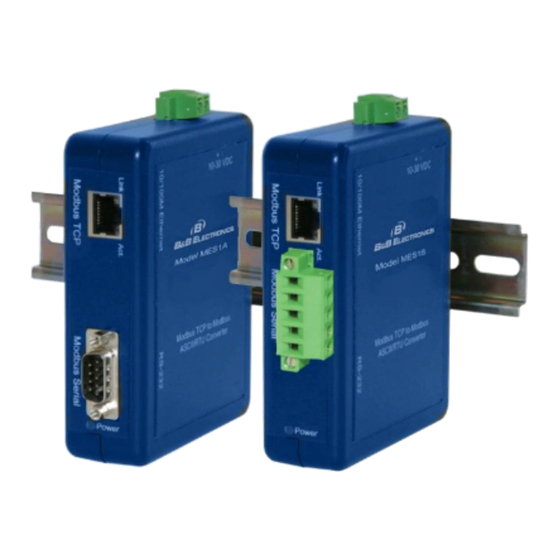
- Page 1 MES1A, MES1B Modbus TCP to Modbus ASCII/RTU Converters...
- Page 2 Phone (815) 433-5100 -- General Fax (815) 433-5105 Website: www.bb-elec.com support@bb-elec.com European Headquarters B&B Electronics Westlink Commercial Park Oranmore, Co. Galway, Ireland Phone +353 91-792444 -- Fax +353 91-792445 Website: www.bb-europe.com techsupport@bb-elec.com © 2014 B&B Electronics – Revised Jan 2014 Document: MES1A-B_R2_0814m.doc...
-
Page 3: Table Of Contents
CHAPTER 3: GETTING STARTED ............... 20 ....................20 UICK TART Check the contents of your MES1A/B package. It should contain… ....20 Set up the Hardware ................... 20 Software Installation ................... 20 Discover the MES1A/B on the Network ............... 21 Configure the MES1A/B .................. - Page 4 AVING .............. 30 ECONFIGURING TO ACTORY ETTINGS To Reconfigure the MES1A to Factory Settings: ..........30 To Reconfigure the MES1B, to Factory Settings: ..........30 Network/IP Settings .................... 30 IP Address ......................31 Default Gateway ....................32 Netmask ......................33 Telnet Configuration Password ................
- Page 5 Use MB/TCP 00BH/00AH Exception Responses ..........41 Disable Modbus/TCP Pipeline ................42 Character Timeout ....................42 Message Timeout ....................43 Serial TX Delay after RX ..................43 Swap 4x/0H to Get 3x/1x ..................43 IP A ..........43 DDRESS OOKUP ABLE ETTINGS Close Idle TCP Sockets After ................
- Page 6 ............... 56 OGGING EARCH AND PGRADE ....................57 SING ....................58 SING CHAPTER 6: MODBUS BASICS ..............59 ASCII/RTU ..................59 ODBUS /TCP ....................60 ODBUS ....................61 INTS AND APPENDIX A: DEFAULT CONFIGURATION SETTINGS ........62 APPENDIX B: PRODUCT SPECIFICATIONS ..........64 APPENDIX C: DIMENSIONAL DIAGRAMS ..........
-
Page 7: Warranty
WARRANTY Limited Lifetime Warranty Effective for products of B&B Electronics Manufacturing Company shipped on or after May 1, 2013, B&B Electronics Manufacturing Company warrants that each such product shall be free from defects in material and workmanship for its lifetime. This limited lifetime warranty is applicable solely to the original user and is not transferable. - Page 8 do not constitute a warranty of any kind, whether express or implied, as to any of the B&B Electronics Manufacturing Company’s products. THE REPAIR OR REPLACEMENT OF THE DEFECTIVE ITEMS IN ACCORDANCE WITH THE EXPRESS WARRANTY SET FORTH ABOVE IS B&B ELECTRONIC MANUFACTURING COMPANY’S SOLE OBLIGATION UNDER THIS WARRANTY.
-
Page 9: Chapter 1: About Your Mes1A/B Converter
RS-485 bus can be connected to the TCP/IP network via the MES1B, allowing them all to be accessed by Modbus TCP/IP devices on the network. Traditional Modbus ASCII/RTU master devices also can be connected to TCP/IP networks using the MES1A/B, making the device appear to be a full Modbus TCP... -
Page 10: Features
It can directly access Modbus TCP slave devices. It also can access other Modbus ASCII/RTU slaves that are connected to the network via other MES1A/B Converters, as if it is talking directly to a Modbus ASCII/RTU slave. FEATURES ... -
Page 11: Chapter 2: Hardware Overview
CHAPTER 2: HARDWARE OVERVIEW PACKAGE CHECKLIST MES1A/B Modbus ASCII/RTU to Modbus TCP Converters are shipped with the following items included: the MES1A or MES1B module a printed version of this user manual a printed version of the MES1A/B Quick Start Guide ... -
Page 12: Indicators, Switches And Connectors
The Power LED illuminates (red) immediately on power up indicating that 10 VDC to 30 VDC power is present on the Power Supply terminals. (Typically 12 VDC is used.) LED Indicators on the MES1A LINK LED When the Link LED located on the Ethernet jack is illuminated it indicates that a connection (link integrity) has been established between the converter and the network. -
Page 13: Activity Led
LED Status Table RESET SWITCH The Reset switch is accessible on the top edge of the MES1A/B (same edge as the power supply connector) through a small hole in the MES1A/B enclosure. It allows you to reset the MES1A/B by inserting a small tool through the hole and pressing the momentary switch for about 1 second. -
Page 14: Rs-422/485 Switch (Mes1B Only)
DTE) supporting RS-232 serial communications including TD (Pin 3), RD (Pin 2) and GND (Pin 5) signal lines. If the Modbus device you are connecting to the MES1A is configured as a DCE you will use a straight-through serial cable. If the Modbus device is configured as a DTE, use a null modem cable. -
Page 15: Rs-422/485 Connector (Mes1B Only)
RS-422/485 CONNECTOR (MES1B ONLY) The RS-422/485 connector on the MES1B is a five position removable terminal block with screw downs. The connector provides screw connections for: Terminal 1 - RDB(+) Terminal 2 - RDA(-) Terminal 3 - TDB(+) ... - Page 16 RS-422/485 FOUR-WIRE MODE When the MES1B is configured to operate in RS-422/485 four-wire mode (RS- 422/485 switch in the left position) its receive terminals are connected to the transmit terminals of the Modbus device it is communicating with. Its transmit terminals are connected to the receive terminals of the Modbus device it is communicating with.
- Page 17 RS-485 TWO-WIRE MODE When the MES1B is configured to operate in RS-485 two-wire mode (RS-422/485 switch in the right position) the two-wire RS-485 two-wire communications cable pair is connected to Terminals TDB and TDA. The communications cable ground/shield is connected to GND. RS-485 Two-Wire Connection No jumpers are required to bridge the transmit and receive lines in two-wire mode.
-
Page 18: Power Connector
The Power Connector is a removable two-position screw terminal block with screw down. The MES1A/B requires between 10 VDC and 30 VDC (3.6 Watts). Typically a 12 VDC power adapter is connected to the terminal block via bare wires. The terminal block can be unplugged to remove the converter from service. - Page 19 Typically, the MES1A/B is connected to the network via a hub switch or router using standard straight-through CAT-5 cable. (If you are connecting the MES1A/B directly to a PC’s network interface a crossover Ethernet cable is required.) MES1A Connections MES1B Connections...
-
Page 20: Chapter 3: Getting Started
SET UP THE HARDWARE Connect the MES1A/B to the network using an Ethernet cable. Connect your PC to the network Connect a 12 VDC power supply (not included) to the MES1A/B and apply power. (10 to 30 VDC, 3.6 Watts.) SOFTWARE INSTALLATION Insert the software CD and it should auto-start into the installation wizard. -
Page 21: Discover The Mes1A/B On The Network
Connect the Modbus device to the serial interface on the MES1A/B using the correct cabling: MES1A is a DTE: Use a straight through serial cable if the Modbus device is a DCE; null modem if device is DTE. MES1B: Four-wire for RS-422, Two-wire for RS-485, Set RS-422/485 switch. -
Page 22: Using The Device Installer Software
This section provides more detailed information on how to install and use the Device Installer software. Device Installer is used to set up and configure the MES1A/B on a network. It detects all MES1A/Bs on the network and allows you to configure the network and serial port settings. -
Page 23: Starting The Device Installer
Devices Tree pane and Device List pane as XPort and XPort IAP respectively. (XPort is the name of the internal module of the MES1A/B.) If you are using an older version of the discovery tool with newer models of the MES1A/B, it will still discover the... -
Page 24: Getting Device Details
Status The Device Installer Main Window GETTING DEVICE DETAILS The Device Installer provides a variety of information about the MES1A/B under the Device Details tab. To access the Device Details tab: 1. Expand the Device Tree by clicking the + symbol next to XPort. -
Page 25: Connecting To The Mes1A/B
CONNECTING TO THE ME S1A/B Before configuration can occur you must set up a telnet connection with the MES1A/B to access the Configuration Menu. You can access the Configuration Menu using a standard telnet window, or use the telnet implementation within the Device Installer software. - Page 26 5. Press the Enter key within five seconds to go into Setup Mode or it will time out (and you will have to click Clear and repeat the process). The MES1A/B Configuration Menu appears. Telnet Configuration Tab with Settings Refer to Chapter 4 for configuration details.
-
Page 27: Chapter 4: Configuring The Mes1A/B
CHAPTER 4: CONFIGURING THE M ES1A/B Configuration of the MES1A/B is accomplished from the Configuration Menu, which is accessed via a standard telnet window, or through the telnet implementation within the Device Installer software. Note: The Web Configuration tab is not used with the MES1A/B. -
Page 28: Navigating The Configuration Menu
NAVIGATING THE CONFI GURATION MENU On initial power-up there are four sections in the MES1A/B configuration menu. A fifth menu item appears if you are configuring a Modbus Master device. The menu items are: 6. Network/IP Settings 7. Serial & Mode Settings 8. -
Page 29: Saving Configuration Settings
SAVING CONFIGURATION SETTINGS When all categories have been configured you must save your configuration to the MES1A/B. To Save the configuration settings to the MES1A/B, at the Select Command or parameter set (1..4) to change: prompt type S. QUITTING WITHOUT SAVING To Quit the configuration session without saving, type Q. -
Page 30: Reconfiguring To Factory Settings
RECONFIGURING TO FAC TORY SETTINGS The MES1A and MES1B come from the factory preconfigured for correct operation with their respective interfaces. The following procedure describes how you can return the MES1A and MES1B to their original factory settings. TO RECONFIGURE THE MES1A TO FACTORY SETTINGS: Type D at the Select Command or parameter set (1..4) to change: prompt. -
Page 31: Ip Address
Network/IP Settings section of the Configuration Menu. Network/IP Settings Menu AUTO-IP If a DHCP server is NOT available on the network, the MES1A/B will revert to Auto-IP and generate its own IP address in the 169.254.xxx.xxx range. STATIC IP ADDRESS The IP address of the MES1A/B can be changed via the Telnet Configuration Menu interface. -
Page 32: Default Gateway
19. Press Enter to accept the new IP address After the new settings have been accepted they will appear in the Configuration Menu. After the Configuration has been saved to the MES1A/B, the new settings will appear in the Device Details tab. -
Page 33: Netmask
Device Details tab. NETMASK Typically you will type N, or just press Enter to cause the MES1A/B to automatically use the standard Netmask appropriate for the IP address being used. The default value for this parameter is ---not set---. -
Page 34: Serial And
PROTOCOL Protocol parameters must be set to match the type of Modbus device (master or slave) connected to the serial side of the MES1A/B device, and the type of Modbus protocol (ASCII or RTU) that will be used. ATTACHED DEVICE Modbus devices operate as either Masters (polling Slaves) or Slaves (responding to polls from Masters). - Page 35 Modbus devices communicate in either of two Serial Protocols: ASCII or RTU. Modbus/ASCII protocol is slower and uses two ASCII characters to represent each 8 bit data byte. Modbus/RTU uses 8 bit binary data characters. The MES1A/B must be configured to use the same protocol used by the attached Modbus device.
-
Page 36: Serial Interface
SERIAL INTERFACE Serial Interface parameters include the type of interface and the data rate/format of the data. The MES1A/B must use the same type of interface and serial parameters as that of the Modbus device it is connected to. MES1A SERIAL INTERFACE Since the MES1A is designed with an RS-232 interface, its default Interface Type is RS-232. - Page 37 No jumpers are required to bridge transmit and receive lines on the terminal block SERIAL PARAMETERS MES1A/B Serial Parameters must be set up to match the parameters of the Modbus device connected to its serial interface. MES1A/B Serial Parameter options include: ...
-
Page 38: Modem/Configurable Pin Settings
CP1 parameter must be set for RS485 Enable to ensure Send Data Control is implemented. No configuration is required in this section for MES1A converters. To configure RS485 Enable in the Modem/Configurable Pin Settings section: 33. Type 3 at the Select Command or parameter set (1..4) to change: prompt. -
Page 39: Slave Address / Unit Id Source
Modbus/RTU device on the serial side of the MES1A/B. When the MES1A/B receives a message (sent to its IP address), it looks at the Unit ID field of the message and passes the message to the specified slave. -
Page 40: Allow Modbus Broadcasts
Modbus/RTU slave (any number in the range of 1 to 255). This limits the number of slaves that can be connected to the MES1A/B to one, but ensures that when any message for the MES1A/B’s IP address is received (regardless of its Unit ID), it is passed along to the slave. -
Page 41: Use Mb/Tcp 00Bh/00Ah Exception Responses
CRC errors with silence. 2 = YES If the Use MB/TCP 00BH/00AH Exception Responses (1=No 2=Yes)is enabled (2 = Yes), the MES1A/B will return the following codes under any of the conditions described: 0A (HEX) - PATH UNAVAILABLE ... -
Page 42: Disable Modbus/Tcp Pipeline
However, when using Modbus/TCP, multiple queries can be issued and the MES1A/B will buffer them in a “pipeline”. The MES1A/B can fetch each query one at a time, and respond. In some situations this is useful, but in others the sequence of query/response can get out of sync (especially if any queries or responses are lost). -
Page 43: Message Timeout
The default value is 5000 milliseconds. SERIAL TX DELAY AFTE R RX When the MES1A/B receives a request from a master it relays the request to the Modbus slave connected to the MES1A/B’s serial connection. When the slave responds a timer is triggered and, after the delay time configured in the Serial TX Delay after TX field, the next master request is allowed to pass through the serial connection to the slave. -
Page 44: Close Idle Tcp Sockets After
Unit ID -> IP Address Table Settings Menu CLOSE IDLE TCP SOCKE TS AFTER The Close Idle TCP Sockets After field allows you to configure whether a socket is held open, or the number of seconds to hold the last socket open. ... -
Page 45: Modbus Address From/To
Type in the four octets of the IP address of the slaves being addressed. If you configure the last octet as 000 the MES1A/B will use the Slave Address/Unit ID of the slave as part of the IP address. This allows a Modbus/RTU master (connected through the MES1A/B) to access up to 255 remote Modbus TCP slaves. -
Page 46: Chapter 5: Using Other Device Installer Features
This section provides a brief overview of those features. For more information, access the Help files from the main menu. Device Installer features which are not used or supported by the MES1A/B include: ... -
Page 47: Saving Device Lists
Open. The MES1A/B will search for all devices listed in the Device List file and display them in the Devices Tree. Devices not listed in the Device List file will not be shown. To discover other devices not already on the list you must initiate a search. - Page 48 DISPLAY DEVICES USING ICONS On the View menu, select Device List, then select Icons. Device List Icon View DISPLAY THE HARDWARE (MAC) ADDRESS On the View menu, select Device Node Text, then select Hardware Address. Device Node Hardware Address View...
-
Page 49: Adding A Device Manually
Device Node Name View ADDING A DEVICE MANU ALLY Although you will typically discover MES1A/B devices on the network using the Search tool, you can also add a device to the network manually. To do so you must know the IP address of the device. -
Page 50: Assigning An Ip Address (Using Device Installer)
Obtain an IP address automatically option in the wizard. 44. If you wish to assign a different IP address to the MES1A/B, select Assign a specific IP address and click Next. The IP Settings page of the wizard appears. -
Page 51: Using The Devices Details Tab
49. The new IP address appears in the Devices Tree, Device Details tab and Telnet Configuration tab. USING THE DEVICES DE TAILS TAB The Device Details tab provides useful information about the MES1A/B currently selected in the Device List. Device Details Tab Although most fields in are fixed, the Name, Group and Comments fields are user configurable, allowing you to add information specific to your application. -
Page 52: Upgrading Firmware
From time to time updated firmware versions for the MES1A/B may become available (from the B&B Electronics website). Device Installer provides a Device Upgrade Wizard which can be used to install updated firmware into the MES1A/B. To install firmware in the MES1A/B: On the Device menu, select Upgrade…, or click the Upgrade icon. -
Page 53: Installing Pre-Saved Configuration Files
The same wizard can be used to install previously saved configuration settings (Setup Records) into the MES1A/B. This can be useful if you want to configure multiple MES1A/Bs with the same settings, or if you must replace an MES1A/B and want to load identical settings into the new unit. -
Page 54: Saving Setup Records
To use the Upgrade Wizard to install configuration setting in an MES1A/B you must first save the settings in the form of a Setup Record. SAVING SETUP RECORDS To save the Setup Records for a particular device (MES1A/B) 55. Select the device in the Device List. - Page 55 Device Upgrade Wizard Step 1 60. Select Create a custom installation by specifying individual files (Typical) and then click Next. 61. In the Device Upgrade Wizard – Step 2 of 5 dialog box, click Next. 62. In the Device Upgrade Wizard – Step 3 of 5 dialog box, select Install setup records from a file, then browse and select the previously saved Setup file.
-
Page 56: Logging Search And Upgrade Data
LOGGING SEARCH A ND UPGRADE DATA Device Installer provides a logging feature that can be used to record and store information on the process of searching for devices or upgrading the MES1A/B. 64. To enable logging select Options… on the Tools menu. The Options dialog box opens. -
Page 57: Using Ping
69. When the search is complete, select Log File on the View menu. Notepad opens and displays the log file. The log file contains the date and time for each entry. Log File in Notepad USING PING Device Installer provides the convenience of implementing the Ping network utility from within the Device Installer window. -
Page 58: Using Help
USING HELP You can access Device Installer Help files by selecting Contents on the Help menu. Device Installer Help... -
Page 59: Chapter 6: Modbus Basics
CHAPTER 6: MODBUS BASICS If you are reading this manual you are probably in the process of interfacing legacy Modbus ASCII/RTU devices to a network. Chances are you already have some knowledge and familiarity with Modbus ASCII/RTU but possibly somewhat less knowledge of Modbus/TCP and/or networking in general. -
Page 60: Modbus/Tcp
master polls individual slaves sequentially. In each poll it sends a message containing a device address, followed by a function code, any data that maybe required, and an error check field. The addressed slave responds with a similar message structure. Typically it repeats back its address and the function code, and then sends a field indicating the number of bytes of data it is sending, followed by the data and the error check field. -
Page 61: Hints And Tips
IP address and always used a Unit ID of 00. If this early equipment is used, only one Modbus/RTU slave can be connected to an MES1A/B. (The MES1B is capable of RS-485 multidrop, allowing multiple slaves.) -
Page 62: Appendix A: Default Configuration Settings
Serial Protocol: Modbus/RTU, Slave MES1A – RS-232 Interface Type: MES1B – RS-422/485 Serial Parameters: 9600, 8, N, 1 MES1A - Not used CP1 Function: MES1B – RS-485 Enabled CP2 Function: Not used CP3 Function: Not used Slave Address: 0 (auto maps to 1) - Page 63 Allow Modbus Broadcasts: 2 (no) Use MB/TCP 00BH/00AH Exception 2 (yes) Responses: Disable Modbus/TCP pipeline: 1 (no) Character Timeout: 50 milliseconds Message Timeout: 5000 milliseconds Serial TX delay after RX: 0 milliseconds Swap 4x/0H to get 3x/1x: No...
-
Page 64: Appendix B: Product Specifications
Operating Systems supported Windows 98/ME/2000/XP/NT 4.0 (call B&B Tech Support for other operating systems) Dimensions MES1A/MES1B – 1.25 x 4.5 x 4.75 in (3.2 x 11.3 x 12.2 Power Supply Requirements: 10 VDC to 30VDC (3.6 Watts) Power Supply: Not included... - Page 65 Operating Temperature: -20 to 80 °C (-4 to 176 °F) Storage Temperature: −40 to 85 °C (−40 to 185 °F) Humidity: 10% to 90% R.H. non-condensing Approvals: CE, FCC Class B Link Integrity Indicator: Green/Orange LED (on Ethernet connector) Activity Indicator: Green/Orange LED (on Ethernet connector) Power Indicator: Red LED...
- Page 66 Serial Protection: 12V TVS for MES1A 5 V TVS for MES1B Serial Connector: MES1A - 9 pin D-type male (DB-9M) MES1B – removable screw terminal (5) block with screw down Interface Lines Supported: MES1A – RS-232 TD, RD, GND MES1B – RS-422/485 TDA(-), TDB(+), RDA(-), RDB(+),...
- Page 67 Configuration Modes: Telnet, XPort Device Installer with integrated Telnet Device Management: SNMP – RFC 1213/1215/1316/131 IP Address Assignment: Static IP or DHCP (IP is set to 0.0.0.0) Accessories: DIN/Panel mount bracket...
-
Page 68: Appendix C: Dimensional Diagrams
APPENDIX C: DIMENSIONAL DIAGRAMS Dimensional Diagram of the MES1A... - Page 69 Dimensional Diagram of the MES1B...
-
Page 70: Appendix D: Serial Connections
APPENDIX D: SERIAL CONNECTIONS DB-9M Signal RS-232 Receive Data Transmit Data Signal Ground RS-232 Connections for DB-9 Connector... - Page 71 Signal Name Label Direction Terminal Receive Data (+) RDB(+) Receive Data (-) RDA(-) Transmit Data (+) TDB(+) Transmit Data (-) TDA(-) Signal Ground MES1B Terminal Block Pin-out for RS-422/485 Four-Wire Operation...
- Page 72 Signal Name Label Direction Terminal Not used used Not used Used DataB (+) TDB(+) In/Out DataA (-) TDA(-) In/Out Signal Ground MES1B Terminal Block Pin-out for RS-485 Two-Wire Operation...
-
Page 73: Appendix E: Network Connections
APPENDIX E: NETWORK CONNECTIONS RJ-45 Pin Signal Wire Color RJ-45 Pin White-Green Green White-Orange Not used Blue Not used White-Blue Orange Not used White-Brown Not used Brown Pin-out for a Standard Ethernet Cable...
Need help?
Do you have a question about the MES1A and is the answer not in the manual?
Questions and answers