Table of Contents
Advertisement
Quick Links
Quick Start Guide
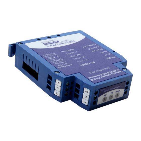
485LDRC9
Optically Isolated RS-232 to
RS-422/485 Converter
1
C
C
h
h
e
e
c
c
k
k
f
f
o
o
r
r
A
A
l
l
l
l
R
R
e
e
q
q
u
u
i
i
r
r
e
e
d
d
485LDRC9 Serial Converter
This Quick Start Guide
Additional Items Required but not included
o Power Supply
o RS-232 cable.
o RS-422/485 Cable.
U
L
I
n
s
t
a
l
l
a
t
i
o
n
I
n
f
o
r
m
U
L
I
n
s
t
a
l
l
a
t
i
o
n
I
n
f
o
r
m
2
Underwriters Laboratories Conditions of Acceptability –
When installed in the end-use equipment, consideration
should be given to the following:
1. The wiring terminals are suitable for factory wiring only.
2. This device is to be mounted in a suitable enclosure in
the end-product.
3. This device is suitable for operation at a maximum
surrounding air temperature as described in the
documentation.
4. These devices are intended for use in a pollution
degree 2 environment.
Input Voltage: 10 – 30 VDC
Input Power: 0.5 Watts
Wire Range: 12 – 24 AWG
Tightening Torque: 4 kgf-cm
Temperature rating of field installed conductors is 105 C
minimum, sized for 60 C ampacity.
Use copper wire only
Maximum surrounding ambient air temperature 80 C.
3
I
n
f
o
I
n
f
o
H
H
a
a
r
r
d
d
w
w
a
a
r
r
e
e
Terminal Block
A
a
t
i
o
n
a
t
i
o
n
B
C
D
E
F
G
H
J
K
L
M
DB9 F Pins (Converter is DCE)
PIN
2
3
5
Note: On the DB9F Connector, control signals are looped
back. Pin 1 (DCD), Pin 4 (DTR), and Pin 6 (DSR) are tied
together. Pin 7 (RTS) and Pin 8 (CTS) are tied together.
–
–
r
m
a
t
i
o
n
C
o
n
n
e
c
t
o
r
s
r
m
a
t
i
o
n
C
o
n
n
e
c
t
o
r
s
Signal
Direction
RS-232 Receive Data (RD)
Output
RS-232 Signal Ground (SG)
-------
Power Ground (PWR GND)
-------
RS-232 Transmit Data (TD)
Input
Put
NOT USED
-------
10 – 30 VDC Power Input
-------
RS-422/485 TD A(-)
Output
RS-422/485 TD B(+)
Output
NOT USED
-------
RS-422/485 RD A(-)
Input
RS-422/485 RD B(+)
Input
Isolated Ground
-------
Signal
Direction
RS-232 Receive Data (RD)
Output
RS-232 Transmit Data (TD)
Input
RS-232 Signal Ground (SG)
-------
Documentation Number –p/n 8413R2 485LDRC9-0812qsg
©2010 B&B Electronics Manufacturing Company
4
I
n
f
o
r
m
a
t
i
o
n
-
D
I
P
S
w
i
I
n
f
o
r
m
a
t
i
o
n
-
D
I
P
S
w
i
Table 3 – Communications Mode
SW-1
SW-2
RS-485
2-Wire
ON
ON
Half Duplex
RS-485
4-Wire
ON
OFF
Full Duplex
RS-422
OFF
OFF
Full Duplex
Table 4 – Termination Resistor
Use the 120Ω
Built in Termination
Use External
or no termination
Table 5 – Timeout Selection
SW-6
SW-7
SW-8
1200
OFF
OFF
OFF
2400
OFF
OFF
ON
4800
OFF
ON
OFF
9600
ON
OFF
OFF
19.2K
ON
ON
ON
38.4K
OFF
OFF
OFF
57.6K
OFF
OFF
OFF
115.2K
OFF
OFF
OFF
Timeout selections are equal to one character time at the
indicated baud rate. Setting the converter 9600 will
generally work at 9600 and higher baud rates. In RS-422
mode, timeouts are not required.
# To achieve these timeouts you must place a through -
hole resistor on the circuit board. See Step 5 for more
information.
t
c
h
t
c
h
SW-3
SW-4
ON
ON
OFF
OFF
OFF
OFF
SW-5
ON
OFF
Timeout
(MS)
8.33
#
4.16
2.08
1.04
0.580
0.260
#
0.176
#
0.0868
#
Advertisement
Table of Contents

Subscribe to Our Youtube Channel
Related Manuals for B&B Electronics 485LDRC9


Summary of Contents for B&B Electronics 485LDRC9
- Page 1 Documentation Number –p/n 8413R2 485LDRC9-0812qsg ©2010 B&B Electronics Manufacturing Company Quick Start Guide 485LDRC9 Optically Isolated RS-232 to RS-422/485 Converter – – Table 3 – Communications Mode SW-1 SW-2 SW-3 SW-4 RS-485 2-Wire Half Duplex RS-485 4-Wire Full Duplex RS-422...
- Page 2 Documentation Number –p/n 8413R2 485LDRC9-0812qsg ©2010 B&B Electronics Manufacturing Company RS-422/ Four Wire RS-485 If you need to support timeouts indicated with a # in Step 4, Table 5, you must place a through-hole resistor on the PCB. Place the resistor in the R-11 spot designated on the board.
Need help?
Do you have a question about the 485LDRC9 and is the answer not in the manual?
Questions and answers