Advertisement
Quick Links
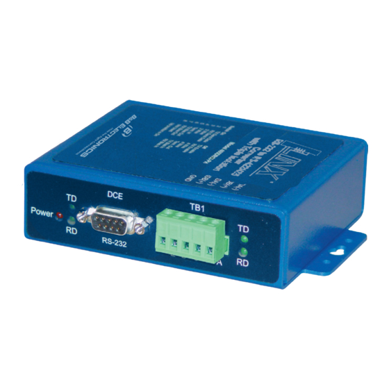
Product Overview
DB9
Terminal
Power
Data
Port
Block
LED
LEDs
Ground
DIP
10 to 48 VDC
lug
Switches
1.9 W Max
Grounding the unit is recommended
Connect a grounding wire from the
ground lug
Set DIP Switches
1
Communications Mode
Switch
1
2
RS-485 2-Wire
ON
ON
Half Duplex
RS-485 4-Wire
ON
OFF
Full Duplex
OFF
OFF
RS-422 Full Duplex
Built-In Termination Resistor
Use built-in 120Ω Termination
Use External or No Termination
Built-In Transmit Bias Resistor
Data
LEDs
Use External or No Bias Resistor
Use built-in 1.2K Ω Transmit Bias Resistor
Built-In Receive Bias Resistor
Use External or No Bias Resistor
Use built-in 1.2K Ω Receive Bias Resistor
SWITCH POSITION 8 IS NOT USED
For an explanation of RS-485 termination and
biasing requirements, refer to B&B Electronics'
RS-485 application note. This publication can
be downloaded at: www.bb-elec.com
3
4
2
ON
ON
OFF
OFF
Terminal
OFF
OFF
A
B
Switch
C
5
D
ON
OFF
E
Switch
6
ON
OFF
Switch
7
ON
OFF
DB9 Pinout
Wire the Converter
RS-422/485
RS-485 2-Wire
4-Wire
***
TDA (-)
***
TDB (+)
Data A (-)
RDA (-)
Data B (+)
RDB (+)
GND
GND
DIP Switch RS-422/485 4-Wire
1
2
3
4
5
OFF
OFF
OFF
***
On/Off
Position 1 = ON for RS-485, OFF for RS-422
Positions 5,6,7 are used for termination and biasing
DIP Switch RS-485 2-Wire
1
2
3
4
5
ON
ON
ON
ON
x
Positions 5,6,7 are used for termination and biasing
Loopback Test
3
C
onfigure for RS-485 Four wire. Jumper terminals A to C and
B to D. Connect a PC to the RS-232 port (see Step 3). Using
HyperTerminal or similar program, connect to the appropriate
COM port. Turn off HyperTerminal local Echo. Transmit data.
The same data should be returned. When data is sent and
looped back, the TD and RD LED's will blink on both ports.
Check LEDs
4
LEDs
Power
Red. ON when power is
LED
applied
Data
Green, LEDs flash when data
LEDs
is present on the port
6
7
***
***
6
7
x
x
Advertisement

Related Manuals for B&B Electronics 485DRCI-PH


Summary of Contents for B&B Electronics 485DRCI-PH
-
Page 1: Product Overview
Product Overview Built-In Transmit Bias Resistor Switch Terminal Power Data Data DIP Switch RS-422/485 4-Wire Port Block LEDs LEDs Use External or No Bias Resistor Use built-in 1.2K Ω Transmit Bias Resistor On/Off Position 1 = ON for RS-485, OFF for RS-422 Built-In Receive Bias Resistor Switch Positions 5,6,7 are used for termination and biasing... -
Page 2: Troubleshooting
Power-Supplies/Industrial-Slimline- specified value. Power-Supplies.aspx A signal ground is required on the 485DRCI-PH because it is DRAD35 an optically isolated device. If you do not have a signal ground (common, reference) on your RS422/485 device, you can DIN Rail Adapter connect to the DC power ground of your RS422/485 device.
Need help?
Do you have a question about the 485DRCI-PH and is the answer not in the manual?
Questions and answers