Advertisement
Quick Links
Quick Start Guide
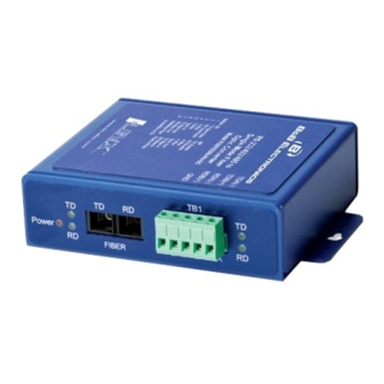
ILinx FOSTCDRI-PH-xx
Triple Isolated Serial to Fiber
Optic Converter
1
1
.
.
C
C
h
h
e
e
c
c
k
k
f
f
o
o
r
r
R
R
e
e
q
q
u
u
i
i
r
r
e
e
d
d
H
H
a
a
r
r
d
d
w
w
ILinx FOSTCDRI-PH-xx Fiber Optic Converter
This Quick Start Guide
Additional Items Required but not included
o A 10 to 48 VDC Power Supply. The Converter
draws 2.6W Max.
–
–
2
.
I
n
f
o
r
m
a
t
i
o
n
U
L
C
l
a
s
s
1
2
.
I
n
f
o
r
m
a
t
i
o
n
U
L
C
l
a
s
s
1
1. Refer to the Nonincendive Field Wiring Apparatus
Control Drawing for important information .
2. Power, Input / output (I/O) wiring for the end use
enclosure must be in accordance with Class 1
Division 2 wiring methods (Article 501.10(B) of the
National Electric Code, NFPA 70) and in
accordance with the local authority having
jurisdiction.
3. Maximum ambient air temperature 85°C.
4. Temperature rating of field installed conductors
105°C. Use Copper Wire Only.
5. These devices must be installed in end use
enclosure suitable for the location.
6. WARNING – EXPLOSION HAZARD
SUBSTITUTION OF COMPONENTS MAY IMPAIR
SUITABILITY FOR CLASS 1, DIVISION 2.
7. WARNING – EXPLOSION HAZARD: DO NOT
DISCONNECT EQUIPMENT UNLESS POWER
HAS BEEN SWITCHED OFF OR THE AREA IS
KNOWN TO BE NON-HAZARDOUS.
8. WARNING – THIS APPARATUS IS SUITABLE
FOR USE IN CLASS 1 DIVISION 2, GROUPS A,
B, C, AND D OR NONHAZARDOUS LOCATIONS
ONLY.
3
.
F
r
o
n
t
/
B
a
c
k
3
.
F
r
o
n
t
/
B
a
c
k
a
a
r
r
e
e
D
i
v
2
D
i
v
2
A
Power LED
B
Data LEDs
Fiber Optic
C
Connectors
D
Serial TB
E
Ground Lug
F
DIP Switch
Serial Mode
G
Switch
H
Power TB
Terminal
RS-485 2-Wire
A
B
C
D
DATA B(+)
E
Terminal
A
B
C
D
E
P
a
n
e
l
,
T
B
1
P
a
n
e
l
,
T
B
1
Red, ON When Power Applied
Green. LEDs Flash When Data is on
Port. Left LED's for Fiber, Right
LED's for Copper
ST or SC, MM or SM, depending on
model.
5 Position, Removable
Chassis Ground to Earth Ground
Used to Configure
Used to configure serial mode. RS-
232 or RS-422/485.
2 Position, Removable
TB1 – RS-422/485
RS-422/485 4-Wire
---
TDA(-)
---
TDB(+)
DATA A(-)
RDA(-)
RDB(+)
Ground
Ground
TB1 – RS-232
Signal
Direction
RD
Output
---
---
TD
Input
---
---
Ground
----
Documentation Number – p/n 8933R1x FOSTCDRI-PH-xx-0812qsg
©2010 B&B Electronics Manufacturing Company
4
.
C
o
n
f
i
g
u
r
a
t
i
o
n
D
I
P
S
w
4
.
C
o
n
f
i
g
u
r
a
t
i
o
n
D
I
P
S
w
Highlighted settings indicate factory default.
Communications Mode
Switch
1
2
RS-485
2-Wire
ON
ON
Half Duplex
RS-485
4-Wire
ON
OFF
Full Duplex
RS-422
OFF
OFF
Full Duplex
Built-in Termination Resistor
Use the 120Ω Built-in Termination
Use External or No Termination
Built-in Transmit Bias Resistor
Use External or No Bias Resistor
Use the 1.2K Ω Transmit Bias Resistor OFF
Built-in Receive Bias Resistor
Use External or No Bias Resistor
Use the 1.2K Ω Receive Bias Resistor
Fiber Optic Mode
Multi-drop Ring
Point-to-Point
For an explanation of RS-485 termination and biasing
requirements, refer to B&B Electronics' RS-485
application note. This publication can be downloaded
at:
www.bb-elec.com
i
t
c
h
i
t
c
h
3
4
ON
ON
OFF
OFF
OFF
OFF
Switch
5
ON
OFF
Switch
6
ON
Switch
7
ON
OFF
Switch
8
ON
OFF
Advertisement

Related Manuals for B&B Electronics ILinx FOSTCDRI-PH Series


Summary of Contents for B&B Electronics ILinx FOSTCDRI-PH Series
- Page 1 Documentation Number – p/n 8933R1x FOSTCDRI-PH-xx-0812qsg ©2010 B&B Electronics Manufacturing Company Quick Start Guide ILinx FOSTCDRI-PH-xx Triple Isolated Serial to Fiber Optic Converter Highlighted settings indicate factory default. Communications Mode Switch ILinx FOSTCDRI-PH-xx Fiber Optic Converter RS-485 This Quick Start Guide 2-Wire ...
- Page 2 Documentation Number – p/n 8933R1x FOSTCDRI-PH-xx-0812qsg ©2010 B&B Electronics Manufacturing Company 2-Wire RS-485 & & Point-to-Point 1. It is recommended that the chassis be grounded. 2. Connect a grounding wire from the ground lug to a good source of Earth Ground. 3.
Need help?
Do you have a question about the ILinx FOSTCDRI-PH Series and is the answer not in the manual?
Questions and answers