RITE-HITE Wheel-Lok GWL-2300 Owner's Manual
Vehicle restraint
Hide thumbs
Also See for Wheel-Lok GWL-2300:
- Owner's manual (42 pages) ,
- Installation manual (12 pages) ,
- Owner's manual (52 pages)

Related Manuals for RITE-HITE Wheel-Lok GWL-2300


Summary of Contents for RITE-HITE Wheel-Lok GWL-2300
- Page 1 GWL-2300 Wheel-Lok Vehicle Restraint Owners Manual MADE IN U.S.A. This Manual Covers Restraints Built After Serial Numbers: GW231001 and up PRINTED IN U.S.A. PUBLICATION NO. 1177 RITE-HITE PRINT SHOP NOVEMBER 2010...
- Page 2 ® representative. The GWL-2300 vehicle restraint by RITE-HITE is intended to provide a safer workplace for workers in shipping and receiving dock areas. The GWL-2300 vehicle restraint is a restraint device that, when properly installed and operated, retains a secure connection between the truck and dock. Signal lights, warning horn and signs provide instructions to the truck driver and GWL-2300 vehicle restraint operator that a safe condition exists.
-
Page 3: Safety Warnings
RITE-HITE ® Corporation does not recommend any particular lockout device, but recommends the utilization of an OSHA approved device (refer to OSHA regulation 1910.147). RITE-HITE ® Corporation also recommends the review and implementation of an entire safety program for the Control of Hazardous Energy (Lockout/Tagout). These regulations are available through OSHA publication 3120. - Page 4 As with any piece of machinery, dock equipment the interface between dock and transport vehicle. requires routine maintenance, lubrication, and The owner should, therefore, train and instruct adjustments. Your local RITE-HITE ® representative operators in the safe use of dock equipment in offers owners the option of a Planned Maintenance accordance with the information provided below.
- Page 5 RITE-HITE ® GWL-2300 Owner’s Manual DEFINITION AND FUNCTION The GWL-2300 vehicle restraint is a truck and trailer The proper activation of the barrier and the locking locking system used to help secure trucks and trailers to mechanism is monitored by: the face of a loading dock.
- Page 6 RITE-HITE ® GWL-2300 Owner’s Manual FEATURES See Figure 4 for locations of these features. HYDRAULIC CYLINDER PAWL ASSEMBLY Assembly Moves the Lifting Rails back and forth, thus raising or which is driven upward into the ratchet by the Lifting Rails lowering the locking pawl into place.
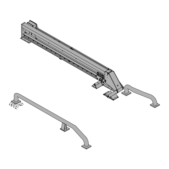
- Page 7 RITE-HITE ® GWL-2300 Owner’s Manual Inside Anchor Sign Control Outside Outside Lights Signs Maintenance Strut Side Covers Maintenance Strut Storage Hooks Barrier Locking Arm Ramp Assembly Barrier Shaft Power Unit Enclosure Pawl Assembly Locking Arm Lifting Rails Trolley Assembly Hydraulic...
-
Page 8: Operating Procedures
RITE-HITE ® GWL-2300 Owner’s Manual OPERATING PROCEDURES Stored Position / Restraint UNLOCKED Restraint Locking, LOCK Button Pressed It is assumed that the loading bay is empty (no truck). If the GWL-2300 vehicle restraint is in the UNLOCKED The outside GREEN light and the inside RED light are position (shaft assembly is down and stored in barrier flashing, the barrier is down. - Page 9 RITE-HITE ® GWL-2300 Owner’s Manual Restraint LOCKED Restraint UNLOCKING, UNLOCK Button If the GWL-2300 vehicle restraint is in the LOCKED Pressed position with the barrier up and the locking mechanism In order to release the truck after completion of the...
- Page 10 RITE-HITE ® GWL-2300 Owner’s Manual FAULT State From LOCKING State HORN OVERRIDE State, HORN OVERRIDE In case the locking mechanism can not engage properly, Code Entered after Securing Trailer by the alarm will sound. The outside and inside lights will Alternate Means show flashing RED.
- Page 11 RITE-HITE ® GWL-2300 Owner’s Manual VEHICLE RELEASE DURING LOSS OF POWER PROCEDURE 1. Lockout/Tagout controls. 2. Remove pin which connects the hydraulic cylinder to Do not remove lock arm when a truck tire is the Lifting Rails. See figure 9.
- Page 12 RITE-HITE ® GWL-2300 Owner’s Manual SNOW REMOVAL PROCEDURE Service Strut Wheel guides, locking arm assembly, trigger, or frame assembly may be buried underneath snow, thus not visible. Unseen obstructions Engage Locking Arm Assembly With Service Strut may cause damage to equipment and/or bodily harm during snow removal if they should come into contact with the snow removal equipment.
- Page 13 Maintenance may be required more frequently at loading docks exposed to harsh environments (extreme climates, corrosive chemicals, frequency of usage exceeding 8 trucks per day, etc.). Consult RITE-HITE if these conditions exist for accelerated maintenance requirements. Lubricate Pawl Shaft Dry Lubricate Only - DO NOT USE Moly Based Grease ®...
- Page 14 RITE-HITE ® GWL-2300 Owner’s Manual 180 DAYS 360 DAYS 1. Do all the Daily and 90 Day maintenance. 1. Do all Daily, 90 and 180 Day maintenance. 2. Tighten the anchor bolts to 100 ft-lbs. 2. Operate unit in (5) different places to ensure the locking mechanism engages properly.
-
Page 15: Troubleshooting
RITE-HITE ® GWL-2300 Owner’s Manual TROUBLESHOOTING When working with electrical or electronic To prevent personal injury use extreme care controls, make sure that the power source has when working with electrically powered been locked out and tagged according to OSHA equipment. - Page 16 RITE-HITE ® GWL-2300 Owner’s Manual Sensing Switch Magnet (LED Off) (LED On) White (LED On) (LED Off) Black FIGURE 14 - SENSING SWITCH TEST AND SWITCH/BARRIER POSITION CHART COMPONENT TESTING multimeter Sensing Switch Test Procedure 1. Set multimeter to “RX1” scale for “Continuity Test”.
- Page 17 RITE-HITE ® GWL-2300 Owner’s Manual LED STATUS CHART LED Inputs LED Outputs STORED (UNLOCKED) LOCKING LOCKED STORING (UNLOCKED) PAWL FAULT HORN SILENCED SWI = MAG RES 1 (LOCK) ISR = Inside Red Light SW2 = MAG RES 2 (UNLOCK) ISG = Inside Green Light...
- Page 18 RITE-HITE ® GWL-2300 Owner’s Manual HORN OVERRIDE CODE AND DIAGNOSTICS SETTING HORN OVERRIDE CODE DIAGNOSTICS Diagnostic mode may be entered while the restraint is in 1. Press and hold DIAGNOSTIC button until horn any state. To enter diagnostic mode: chirps (approximately three seconds).
- Page 19 RITE-HITE ® GWL-2300 Owner’s Manual Steps 12 – 15 are used to test the mechanical Inputs and Outputs of the lock (i.e. motor, sensors, etc.). The horn will chirp when the controls enter Steps 12 – 15 to alert the operator to check the hook position. If the sensor...
- Page 20 RITE-HITE ® GWL-2300 Owner’s Manual ELECTRICAL SCHEMATIC (STANDARD) to customer power supply, 120V, 60Hz, 30 amp fused disconnect with 10 amp ground non-time delay fusing lugs (supplied by others) motor power common module motor lock 1A, 250V control motor fuse...
- Page 21 RITE-HITE ® GWL-2300 Owner’s Manual ELECTRICAL SCHEMATIC (OPTIONS MODULE) NOTE: The standard wiring is not shown in this drawing to better show the option module wiring. For information on standard wiring, see previous page. power module circuit breaker reset button...
- Page 22 RITE-HITE ® GWL-2300 Owner’s Manual OUTSIDE LIGHT BOX WIRING #40 Wire White Wire Red Wire #42 Wire Red Lamp Red Wire Green Lamp #41 Wire White Wire Light Box Cover FIGURE 20 - OUTSIDE LIGHT BOX WIRING Pub. No. 1177 - November 2010...
- Page 23 RITE-HITE ® GWL-2300 Owner’s Manual NOTES Pub. No. 1177 - November 2010...
- Page 24 RITE-HITE ® GWL-2300 Owner’s Manual TRACK ASSEMBLY REPLACEMENT PARTS NOTE: Use loctite on screw. DO NOT over torque. Detail C Detail D Detail F 3, 4 NOTE: Use loctite on screw. DO NOT over torque. NOTE: Distance from back of nut to back of switch (wire end) is 5/16".
- Page 25 RITE-HITE ® GWL-2300 Owner’s Manual TRACK ASSEMBLY PARTS LIST Item Description Part Number Back Side Cover 106944 Maintenance Strut 106943 Hex. Cap Screw 1/4"-20 x 1/2" Long Stainless Steel 106939 Washer 1/4" Stainless Steel 106956 Front Side Cover 106947 Screw .250-20 x .875" Cap Button, Stainless Steel 106918 1/4”...
- Page 26 RITE-HITE ® GWL-2300 Owner’s Manual WHEEL GUIDES & BARRIER RAMP REPLACEMENT PARTS Item Description Part Number Wheel Guide Long 100262 Barrier Ramp 107633 Anchor Bolt 5/8" x 4" 53150 Wheel Guide Short 100263 Pub. No. 1177 - November 2010...
- Page 27 RITE-HITE ® GWL-2300 Owner’s Manual LOCKING ARM ASSEMBLY REPLACEMENT PARTS Locking Arm Assembly (Complete) Item Qty Description Part Number Locking Arm Assembly - Complete (Includes items 2-20) 120032 Screw Hex Head 1/2”-13 x 1-1/2” Long (Grade 8) 121249 Locking Arm Tube Retainer 122510 Round Tube 14-13/16"...
- Page 28 RITE-HITE ® GWL-2300 Owner’s Manual LOCKING ARM TROLLEY REPLACEMENT PARTS Locking Arm Trolley (Complete) 12 13 Item Qty Description Part Number Locking Arm Trolley Assembly - Complete (Includes Items 2 - 19) 109234 Screw, Hex. Head 5/8-11 x 1-1/2" Long Stainless Steel 106935 Lockwasher 5/8"...
- Page 29 RITE-HITE ® GWL-2300 Owner’s Manual PAWL ASSEMBLY REPLACEMENT PARTS Pawl Assembly (complete) Front View Side View Item Qty Description Part Number Pawl Assembly - Complete 112584 Pawl Weldment 112585 UHMW Slider 112756 Snaggletooth 106922 Pawl Wear Pad 106934 Pop Rivet 106954 Hex.
- Page 30 RITE-HITE ® GWL-2300 Owner’s Manual TRIGGER ASSEMBLY REPLACEMENT PARTS Item Qty Description Part Number Trigger Assembly – Complete 106893 Trigger Weldment 106894 Round Tube 2-1/2" OD, 1-1/2" ID x 5-1/8" Long 106913 Cap Screw 1/4-20 x 2-1/4" Long Stainless Steel 106908 Shaft 1-7/16"...
- Page 31 RITE-HITE ® GWL-2300 Owner’s Manual TRIGGER TROLLEY ASSEMBLY REPLACEMENT PARTS Trigger Trolley Assembly (Complete) Item Qty Description Part Number Trigger Trolley Assembly - Complete (Includes Items 2 - 13) 109233 Screw, Hex. Head 5/8-11 x 1-1/2" Long Stainless Steel 106935 Lockwasher 5/8"...
- Page 32 RITE-HITE ® GWL-2300 Owner’s Manual ELECTRICAL REPLACEMENT PARTS Pub. No. 1177 - November 2010...
- Page 33 CPU module – includes mounting hardware 113365 Options module, not included in STANDARD control box assembly 105448 Program configuration decal (Consult RITE-HITE for specific part) 107.xxx Full Load Amp and Voltage Decal (Consult RITE-HITE for specific part) 110.xxx Horn, 12VDC 57383 Wiring harness 105460...
- Page 34 4” GWL-2300 ® Vehicle Restraint 12-1/4” 10” SERIAL N O. G W231001 & U P Owner’s Manual Printed in U.S.A. b y RITE-HITE®Print Shop Publication No. 1177 Copyright 2003 RITE-HITE ® Febuary 2003 6-1/4” 3” Item Qty Description Part Number...
- Page 35 RITE-HITE ® GWL-2300 Owner’s Manual HYDRAULIC POWER UNIT REPLACEMENT PARTS 6, 7 Door Hinge on This Side (Removed for Clarity) 13, 16 8, 17 14, 4 Jam Nut Comes With Item #10 Item Qty Description Part Number Power Unit 120/1ph/.33hp...
- Page 36 RITE-HITE ® GWL-2300 Owner’s Manual LEFT HAND TRACK ASSEMBLY REPLACEMENT PARTS NOTE: Use loctite on screw. DO NOT over torque. Detail F Detail D Detail C 17 16 NOTE: Use loctite on screw. DO NOT over torque. NOTE: Distance from back of nut to back of switch (wire end) is 5/16".
- Page 37 RITE-HITE ® GWL-2300 Owner’s Manual LEFT HAND TRACK ASSEMBLY PARTS LIST Item Description Part Number Back Side Cover 109898 Maintenance Strut 106943 Hex. Cap Screw 1/4"-20 x 1/2" Long Stainless Steel 106939 Washer 1/4" Stainless Steel 106956 Front Side Cover 109899 Screw .250-20 x .875"...
- Page 38 RITE-HITE ® GWL-2300 Owner’s Manual LEFT HAND WHEEL GUIDES & BARRIER RAMP REPLACEMENT PARTS Item Description Part Number Wheel Guide Long 110072 Barrier Ramp 107633 Anchor Bolt 5/8" x 4" 53150 Wheel Guide Short 110073 Pub. No. 1177 - November 2010...
- Page 39 RITE-HITE ® GWL-2300 Owner’s Manual LEFT HAND LOCKING ARM ASSEMBLY REPLACEMENT PARTS Locking Arm Assembly (Complete) 16 15 14 Item Qty Description Part Number Locking Arm Assembly - Complete (Includes items 2-20) 121345 Screw Hex Head 1/2”-13 x 1-1/2” Long (Grade 8)
- Page 40 RITE-HITE ® GWL-2300 Owner’s Manual LEFT HAND LOCKING ARM TROLLEY REPLACEMENT PARTS Locking Arm Trolley (Complete) 13 12 11 Item Qty Description Part Number Locking Arm Trolley Assembly - Complete (Includes Items 2 - 19) 110035 Screw, Hex. Head 5/8-11 x 1-1/2" Long Stainless Steel 106935 Lockwasher 5/8"...
- Page 41 RITE-HITE ® GWL-2300 Owner’s Manual LEFT HAND PAWL ASSEMBLY REPLACEMENT PARTS Pawl Assembly (complete) Front View Side View Item Qty Description Part Number Pawl Assembly - Complete 127221 Pawl Weldment 127220 UHMW Slider 112756 Snaggletooth 106922 Pawl Wear Pad 106934...
- Page 42 RITE-HITE ® GWL-2300 Owner’s Manual LEFT HAND TRIGGER ASSEMBLY REPLACEMENT PARTS Item Qty Description Part Number Trigger Assembly – Complete 108693 Trigger Weldment 108694 Round Tube 2-1/2" OD, 1-1/2" ID x 5-1/8" Long 106913 Cap Screw 1/4-20 x 2-1/4" Long Stainless Steel 106908 Shaft 1-7/16"...
- Page 43 RITE-HITE ® GWL-2300 Owner’s Manual LEFT HAND TRIGGER TROLLEY ASSEMBLY REPLACEMENT PARTS Trigger Trolley Assembly (Complete) Item Qty Description Part Number Trigger Trolley Assembly - Complete (Includes Items 2 - 13) 110069 Screw, Hex. Head 5/8-11 x 1-1/2" Long Stainless Steel 106935 Lockwasher 5/8"...
- Page 44 RITE-HITE ® GWL-2300 Owner’s Manual LEFT HAND HYDRAULIC POWER UNIT REPLACEMENT PARTS Door Hinge on This Side 6, 7 (Removed for Clarity) 8, 17 4, 14 Jam Nut Comes With Item #10 Item Qty Description Part Number Power Unit 120/1ph/.33hp...
- Page 45 RITE-HITE ® GWL-2300 Owner’s Manual NOTES Pub. No. 1177 - November 2010...
- Page 46 RITE-HITE ® GWL-2300 Owner’s Manual NOTES Pub. No. 1177 - November 2010...
- Page 47 RITE-HITE ® GWL-2300 Owner’s Manual NOTES Pub. No. 1177 - November 2010...
- Page 48 ® in writing. ® In the event of any defects covered by this warranty, RITE-HITE will remedy such defects by repairing or replacing any defective equipment or parts, bearing all the costs for parts, labor, and transportation. This shall be the exclusive remedy for all claims whether based on contract, negligence, or strict liability.
Need help?
Do you have a question about the Wheel-Lok GWL-2300 and is the answer not in the manual?
Questions and answers