
Related Manuals for TSC TTP 243 Plus


Summary of Contents for TSC TTP 243 Plus
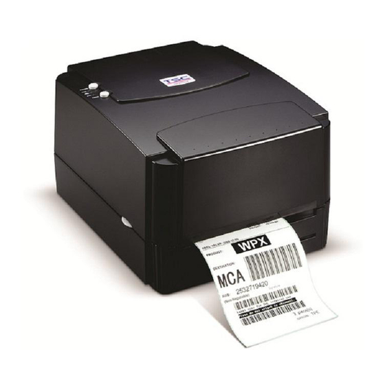
- Page 1 TTP 243 Plus/ 243E Plus/ 342 Plus THERMAL TRANSFER / DIRECT THERMAL BAR CODE PRINTER Service Manual TTP/TDP 244/342 TTP/TDP 244...
-
Page 2: Table Of Contents
TTP-243 Plus/ 243E Plus/ 342 Plus Bar Code Printer Table of Contents FUNDAMENTALS ABOUT THE SYSTEM ..............1 1.1 Features of the TTP-243 Series ................. 1 1.2 Model Naming Syntax ....................1 1.3 Overview ........................2 1.3.1 Front View ......................2 1.3.2 Rear View ...................... - Page 3 TTP-243 Plus/ 243E Plus/ 342 Plus Bar Code Printer 3.15 Cutter, DC Motor, Stepping Motor Driver IC Replacement ........30 4. MECHANISM ........................31 4.1 Cutter Installation ..................... 31 4.2 Print Head Replacement ..................32 4.3 DC Motor Replacement .................... 34 4.4 Ribbon Rewind Spindle Encoder Replacement ............
-
Page 4: Fundamentals About The System
TTP-243 Plus/ 243E Plus/ 342 Plus Bar Code Printer 1. FUNDAMENTALS ABOUT THE SYSTEM 1.1 Features of the TTP-243 Series 1. This bar code printer prints bar codes, characters, logos, on various types of labels and tickets by direct thermal or thermal transfer printing. 2 This printer adopts a “BASIC-like”... -
Page 5: Overview
TTP-243 Plus/ 243E Plus/ 342 Plus Bar Code Printer 1.3 Overview 1.3.1 Front View Operation Panel Top Cover Cover Release Button Front Panel Fig. 1.1 Front View Note: The one difference between TTP model and TDP model is the ribbon mechanism. -
Page 6: Rear View
TTP-243 Plus/ 243E Plus/ 342 Plus Bar Code Printer 1.3.2 Rear View Label Entrance (External Mount Use) Centronics Interface RS-232 Interface Power Switch DC Power Jack Fig. 1.2 Rear view... -
Page 7: Basic Specifications
TTP-243 Plus/ 243E Plus/ 342 Plus Bar Code Printer 1.4 Basic Specifications Thermal transfer and direct thermal printing High dot density printing (203 dots/inch) Selectable print speeds at 1.5”, 2.0” or 3.0” per second Supports parallel and serial interface Maximum media width up to 4.4”... - Page 8 TTP-243 Plus/ 243E Plus/ 342 Plus Bar Code Printer Host Function 9 Pin 25 Pin 9 Pin Printer Function...
-
Page 9: Effective Print Area
TTP-243 Plus/ 243E Plus/ 342 Plus Bar Code Printer 1.5 Effective Print Area Label/Ticket Length 12mm~2286mm Effective Print 10mm~2284mm Length Label/Ticket Width 25mm~103mm Effective Print Width 23mm~101mm No Print Area 1.6 Available Bar Codes Code 39 Code 93 ... -
Page 10: Various Sensors
TTP-243 Plus/ 243E Plus/ 342 Plus Bar Code Printer 1.7 Various Sensors Feed Gap Sensor The feed gap sensor detects a label gap to locate the starting print position of the next label. The sensor is mounted 4 mm off the center line of the main mechanism. In case of Label Black Mark Sensor The black mark sensor locates the position of label by emitting infrared rays onto the... - Page 11 TTP-243 Plus/ 243E Plus/ 342 Plus Bar Code Printer In case of Ticket The default sensor position is (1) as shown on the figure below. To change to the (2) position, the customer should notify the manufacturer in advance. There can be only one position for the sensor.
-
Page 12: Supply Specifications
TTP-243 Plus/ 243E Plus/ 342 Plus Bar Code Printer 2. SUPPLY SPECIFICATIONS 2.1 Types of Paper Two types of media are available for TTP-243: label and ticket. In TTP-243, there are two types of sensors for paper: gap sensor and black mark sensor. - Page 13 TTP-243 Plus/ 243E Plus/ 342 Plus Bar Code Printer...
-
Page 14: Ribbon Sizes And Shapes
TTP-243 Plus/ 243E Plus/ 342 Plus Bar Code Printer 2.3 Ribbon Sizes and Shapes Item Specifications Ribbon shape Spool type Max. 110mm Ribbon width Min. 40mm Max. 110mm Ribbon winding width Min. 40mm Leading tape Polyester film, 3355mm long End tape Polyester film (transparent), 2505mm long 67mm... -
Page 15: Electronics
TTP-243 Plus/ 243E Plus/ 342 Plus Bar Code Printer 3. ELECTRONICS 3.1 Circuit Description Fig. 3.1 MCU Circuit Diagram The above is the MCU circuit diagram. The main board includes seven system blocks: A: MCU & Decode System B. Memory System C. - Page 16 TTP-243 Plus/ 243E Plus/ 342 Plus Bar Code Printer G. Power System The figure below shows the PCB system area. Communication Port Motor System Memory Decoder System Print Head External Memory Real Time Memory Power Cutter System Clock Connector System System...
-
Page 17: Mcu Pin Description
TTP-243 Plus/ 243E Plus/ 342 Plus Bar Code Printer 3.2 MCU Pin Description Port Initial High Function Instruction Pull Up RXD0 RXD for RS232 TXD0 TXD for RS232 Pull Up RTS for RS232 CTS for RS232 TXD1 DI for TPH SCK1 CLK for TPH Pull Up... - Page 18 TTP-243 Plus/ 243E Plus/ 342 Plus Bar Code Printer Enable PF2 MEM load & Hardware version CT DETECT PEEL SENS RIBBON SENS BM SENS GAP SENS Pull Up No use /RESETP Pull Up Active /RESETP /RESET /WDTOVF /WDTOVF No use IRQ0: NO USE IRQ1: NO USE IRQ2: POWER DOWN...
-
Page 19: Reset Circuit
TTP-243 Plus/ 243E Plus/ 342 Plus Bar Code Printer 3.3 Reset Circuit Fig. 3.3 Reset Circuit This is the reset circuit .The TS809CXA IC outputs the system reset signal of “LOW” when the driving voltage is lower than 4.63V (Typical),U31 NO use. 3.4 Memory System Fig. -
Page 20: Sensor&Key
TTP-243 Plus/ 243E Plus/ 342 Plus Bar Code Printer 3.5 Sensor&Key Fig. 3.5 Sensor&Key JP1 is the connector which connects to the LEDs and Keys. The signal of LED is High when the LED is bright; otherwise, it is low. JP2 is the connector of the head open sensor. -
Page 21: Real-Time Clock Circuit
TTP-243 Plus/ 243E Plus/ 342 Plus Bar Code Printer 3.6 Real-Time Clock Circuit Fig. 3.6 Real-Time Clock Circuit HT1381 is serial time Keeper. -
Page 22: Decode Circuit
TTP-243 Plus/ 243E Plus/ 342 Plus Bar Code Printer 3.7 Decode Circuit... - Page 23 TTP-243 Plus/ 243E Plus/ 342 Plus Bar Code Printer CS0: (0000 0000 ~ 003F FFFF) CS1: (0040 0000 ~ 007F FFFF) CS2: (0080 0000 ~ 00BF FFFF) CS3: (00C0 0000 ~ 0FFF FFFF) ROM1: (0000 0000 ~ 001F FFFF) ROM2: (0020 0000 ~ 003F FFFF) Memory card :(0040 0000~007F FFFF) Download ROM: (0800 0000 ~ 09F FFFF) DRAM: (0100 0000~011F~FFFF)
-
Page 24: Thermal Head Drive/ Protection And History Control Circuit
TTP-243 Plus/ 243E Plus/ 342 Plus Bar Code Printer 3.8 Thermal Head Drive/ Protection and History Control Circuit Fig. 3.9 Thermal Head Drive/ Protection and History Control Circuit This is the thermal head drive circuit. CLK and /LAT connected to thermal head control clock and data latch respectively. -
Page 25: 5V Converter Circuit
TTP-243 Plus/ 243E Plus/ 342 Plus Bar Code Printer 3.9 24V/5V Converter Circuit Fig. 3.10 24V/5V Converter Circuit Figure 3.9 is the DC-TO-DC (DC24V to DC 5V) converter circuit, which is a step-down system circuit structure. U24 is the DC-TO-DC converter IC, which can convert voltage by using PWM control mode. -
Page 26: Stepping Motor And Dc Motor Driver/ Protection Circuit
TTP-243 Plus/ 243E Plus/ 342 Plus Bar Code Printer 3.10 Stepping Motor And DC Motor Driver/ Protection Circuit Fig. 3.10 Stepping Motor And DC Motor Driver/ Protection Circuit This is the Stepping Motor Drive. Connector JP12 sends the pattern as shown in table1. The status of I0 &... -
Page 27: Communication (Serial & Parallel Port) Circuit
TTP-243 Plus/ 243E Plus/ 342 Plus Bar Code Printer 3.11 Communication (Serial & Parallel Port) Circuit Fig. 3.11 Parallel port and RS-232 Circuit The RS-232 Circuit is for use with the externally connected personal computer and keyboard unit. JP13 connects to PC serial port through the RS-232 cable. RxD is the data receive pin of MCU. -
Page 28: Cutter Drive Circuit
TTP-243 Plus/ 243E Plus/ 342 Plus Bar Code Printer 3.12 Cutter Drive Circuit Fig. 3.12 Cutter Drive Circuit This is the cutter drive circuit. The RESET signal is 1 when the printer is turned on. /CT_EN controls the activation of the cutter. The cutter is activated when CUTTER signal is “low”. -
Page 29: Mainboard Replacement
TTP-243 Plus/ 243E Plus/ 342 Plus Bar Code Printer 3.14 Mainboard Replacement 1. Turn off the printer power. 2. Remove the power cord and RS-232 and/or parallel port cable. 3. Open the top cover of the printer. 4. Remove the printer front panel. Fig. - Page 30 TTP-243 Plus/ 243E Plus/ 342 Plus Bar Code Printer 6. Release the cable tie and remove the peel-off sensor connector. Peel-Off Sensor Connector Cable Tie Cutter Connector Fig. 3.16 Cable tie and peel-off sensor connector 7. Remove the screws on the lower left and lower right corners of main mechanism. Fig.
- Page 31 TTP-243 Plus/ 243E Plus/ 342 Plus Bar Code Printer 8. Remove the four screws of the internal label roll mount. Fig. 3.18 Remove screws of the label roll mount 9. Move the mechanism about 5 mm in the label feed direction. 10.
-
Page 32: Ttp-243 Plus/ 243E Plus/ 342 Plus Bar Code Printer
TTP-243 Plus/ 243E Plus/ 342 Plus Bar Code Printer 11. Remove the screw of ground wire on the mainboard. 12. Remove all connectors on the mainboard. (JP1, JP2, JP3, JP4, JP5, JP6, JP7, JP11, JP7, JP9, JP12) Connector Description External button, LED connector Ribbon sensor receiver connector Cutter and Peel off sensor connector Black mark sensor connector... -
Page 33: Cutter, Dc Motor, Stepping Motor Driver Ic Replacement
TTP-243 Plus/ 243E Plus/ 342 Plus Bar Code Printer 3.15 Cutter, DC Motor, Stepping Motor Driver IC Replacement FLASH Memory Cutter Driver IC DC Motor Stepping Driver IC Motor Driver IC Fig. 3.22 Driver IC Locations If the DC motor (ribbon rewind spindle) rotates back and forth, please check the DC motor driver IC, make sure it is firmly inserted in the IC socket and is not burned. -
Page 34: Mechanism
TTP-243 Plus/ 243E Plus/ 342 Plus Bar Code Printer 4. MECHANISM 4.1 Cutter Installation 1. Turn off the printer power. 2. Open the top cover of the printer. 3. Remove the printer front panel slowly and carefully. (Cf. Fig. 3.14) 4. -
Page 35: Print Head Replacement
TTP-243 Plus/ 243E Plus/ 342 Plus Bar Code Printer 4.2 Print Head Replacement 1. Turn off the printer power. 2. Remove the RS-232 cable and power cord. 3. Open the top cover. 4. Remove the ribbon and label roll. 5. Open the print carriage. 6. - Page 36 TTP-243 Plus/ 243E Plus/ 342 Plus Bar Code Printer Note: The key of connector must be positioned upward. Do not touch the elements of the print head. Do not disassemble the print head. 8. Tidy up the cable so that it does not protrude or interfere with the ribbon. 9.
-
Page 37: Dc Motor Replacement
TTP-243 Plus/ 243E Plus/ 342 Plus Bar Code Printer 4.3 DC Motor Replacement 1. Turn off the printer power. 2. Remove the power cord and RS-232 and/or parallel port cable. 3. Open the top cover of the printer. 4. Remove the printer front panel. (Cf. Fig. 3.14) 5. - Page 38 TTP-243 Plus/ 243E Plus/ 342 Plus Bar Code Printer to measure the voltage of Pin2 (+5V). If the voltage changes continuously from 0 to 5 volts DC, the encoder is in condition. Otherwise, please follow the steps below to replace the encoder PCB 1.
-
Page 39: Felt Fabric Replacement
TTP-243 Plus/ 243E Plus/ 342 Plus Bar Code Printer 4.5 Felt Fabric Replacement Felt Fabric is located in the ribbon supply spindle. It is used to tighten the ribbon to prevent it from getting wrinkled during printing. If the ribbon can not be tightened when label back feeds during printing, please replace with a new felt to secure the best printing quality. - Page 40 TTP-243 Plus/ 243E Plus/ 342 Plus Bar Code Printer 6. Reassemble the removed parts in the reverse order of removal. Fig. 4.8 Front View of the Ribbon Supply Spindle...
-
Page 41: Stepping Motor Replacement
TTP-243 Plus/ 243E Plus/ 342 Plus Bar Code Printer 4.6 Stepping Motor Replacement 1. Turn off the printer power. 2. Remove the power cord and RS-232 and/or Parallel port cable. 3. Open the top cover of the printer. 4. Remove the printer front panel. (Cf. Fig. 3.14) 5. -
Page 42: Black Mark Sensor / Gap Sensor (Receiver) Replacement
TTP-243 Plus/ 243E Plus/ 342 Plus Bar Code Printer 4.7 Black Mark Sensor / Gap Sensor (Receiver) Replacement Black mark sensor is reflection type sensor. It is connected to JP4 (3 pin connector). A multi-meter is used to measure the signal of Pin2 to see if there is voltage variation when black mark is detected. - Page 43 TTP-243 Plus/ 243E Plus/ 342 Plus Bar Code Printer 5. Remove the two screws and the metal cover. (Cf. Fig. 3.15) 6. Release the cable tie and remove the peel-off sensor connector. (Cf. Fig. 3.16) 7. Remove the screw on the PCB of peel-off and cutter connector. 8.
- Page 44 TTP-243 Plus/ 243E Plus/ 342 Plus Bar Code Printer Fig. 4.12 Ribbon Sensor Fig. 4.13 Spring Installation on Left Side and Right Side Note: The left side spring and the right side spring are different in shape. The right side spring has a straight end, when the left side spring has an end that is curved 90 degrees.
-
Page 45: Ribbon Sensor (Transmitter) / Gap Sensor (Transmitter) Replacement
TTP-243 Plus/ 243E Plus/ 342 Plus Bar Code Printer 4.9 Ribbon Sensor (Transmitter) / Gap Sensor (Transmitter) Replacement 1. Please follow the steps in Section 4.6 to separate the upper mechanism from the lower mechanism. 2. The ribbon sensor (transmitter) is located in the center of the lower mechanism. Fig. -
Page 46: Platen Replacement
TTP-243 Plus/ 243E Plus/ 342 Plus Bar Code Printer 4.10 Platen Replacement 1. Turn off the printer power. 2. Remove the power cord and RS-232 and/or parallel port cable. 3. Open the top cover of the printer. 4. Remove the printer front panel. (Cf. Fig. 3.4) 5. - Page 47 TTP-243 Plus/ 243E Plus/ 342 Plus Bar Code Printer Bracket Thermal Head Printer Carriage Release Lever E Ring Fig. 4.16 Printer carriage release lever and E ring Stripper Platen Bush Printer (Right Side) Carriage Release Lever Teflon Tube E Ring Fig.
- Page 48 TTP-243 Plus/ 243E Plus/ 342 Plus Bar Code Printer Teflon Tube Fig. 4.18 Teflon tube and stripper rod Platen Bush (Left Side) E Ring Fig. 4.19 Remove E ring and platen bush 22. Move the platen to the right of the mechanism. 23.
-
Page 49: Trouble Shooting
TTP-243 Plus/ 243E Plus/ 342 Plus Bar Code Printer 5. TROUBLE SHOOTING 5.1 Error Messages Syntax Error: The command format is incorrect. Check user‟s manual to be sure. The serial port setting is incorrect. Check DIP switch and reset the printer. Out of Range: Numeric input is too large to be processed. -
Page 50: Trouble Shooting
TTP-243 Plus/ 243E Plus/ 342 Plus Bar Code Printer 5.2 Trouble Shooting Problems Solutions 1. Ribbon does not advance. Check the printing mode setting and reset the printer. 2. Poor print quality. Clean the print head. Adjust the print density setting. 3. -
Page 51: Calibrate The Gap Register
TTP-243 Plus/ 243E Plus/ 342 Plus Bar Code Printer 5.3 Calibrate the Gap Register Install the label. Turn on the printer power while pressing the PAUSE button. The printer will calibrate the transparency of the backing paper and adjust the gap register. 5.4 Self-test Install the label. -
Page 52: Testing Sensors
TTP-243 Plus/ 243E Plus/ 342 Plus Bar Code Printer 5.7 Testing Sensors A. Checking Ribbon Sensor Switch the multimeter to the DC gear. Connect the black wire to DC GND, and the red wire to PIN2 of JP2. 1. When ribbon is detected between TX and RX of the ribbon sensor, the measured voltage should be 5 Vdc. - Page 53 TTP-243 Plus/ 243E Plus/ 342 Plus Bar Code Printer D. Checking Black Line Sensor Switch the multimeter to the DC gear. Connect the black wire to DC GND, and the red wire to PIN2 of JP4. Load black line label on the printer. 1.
-
Page 54: Cleaning The Print Head
TTP-243 Plus/ 243E Plus/ 342 Plus Bar Code Printer 5.8 Cleaning the Print Head The printer should be cleaned regularly to retain high quality and optimum performance. The greater the usage of the printer, the more frequent the cleaning. 1. Always turn off the printer before cleaning the print head. Allow the printhead to cool for a minimum of one minute. - Page 55 Camille 98-0180157-30LF/31LF/32LF to 98-0180157-40LF/41LF/42LF 2007/3/9 1. Modify the 4-11 item 5-5 : External Ethernet print server(C) part no. Camille 2007/4/14 1. Update TSC e-mail address. Camille 2. Update 5.8 section:cleaning the print head. 2007/8/1 1. Company information update. Camille 2007/11/8 1.
- Page 56 9F., No.95, Minquan Rd., Xindian Dist., No.35, Sec. 2, Ligong 1st Rd., Wujie Township, New Taipei City 23141, Taiwan (R.O.C.) Yilan County 26841, Taiwan (R.O.C.) TEL: +886-2-2218-6789 TEL: +886-3-990-6677 FAX: +886-2-2218-5678 FAX: +886-3-990-5577 Web site: www.tscprinters.com TSC Auto ID Technology Co., Ltd. E-mail: printer_sales@tscprinters.com tech_support@tscprinters.com...
Need help?
Do you have a question about the TTP 243 Plus and is the answer not in the manual?
Questions and answers