TSC TTP-246M User Manual
Thermal transfer / direct thermal bar code printer
Hide thumbs
Also See for TTP-246M:
- Programming manual (434 pages) ,
- User manual (79 pages) ,
- Service manual (47 pages)
Table of Contents
Advertisement
Advertisement
Table of Contents

Related Manuals for TSC TTP-246M


Summary of Contents for TSC TTP-246M
- Page 1 TTP-246M/344M THERMAL TRANSFER / DIRECT THERMAL BAR CODE PRINTER USER’S MANUAL...
-
Page 3: Table Of Contents
3.5 Peeler Kit Installation (Option)..............10 3.6 Loading Label For Peel-off Mode ..............16 3.7 Self-test ......................18 3.8 Dump Mode....................19 4. USING TTP-246M/344M .............21 4.1 Power-on Utilities ................... 21 4.1.1 Gap/Black Mark Sensor Calibration Utility..........21 4.1.2 Printer Initialization ................22 4.2 Troubleshooting Guide ................... -
Page 5: Product Introduction
1. PRODUCT INTRODUCTION Thank you very much for purchasing TSC TTP-246M/344M bar code printer. TTP-246M/344M comes with rugged steel construction and durable metal mechanism ensuring the ability to work under extreme industrial applications. TTP-246M/344M is equipped with a 32-bit RISC multi-tasking processor, which offers up to 6 ips for 246M and 4”/sec for 344M print speed. -
Page 6: Getting Started
2. GETTING STARTED Unpacking and Inspection After receiving the bar code printer, carefully inspect the device and its packaging. The printer is specially packaged to withstand damage in shipping. In case of evident damage, contact the carrier directly to specify the nature and extent of damage. -
Page 7: Printer Parts
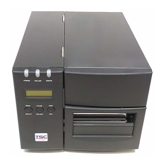
Printer Parts LED indicator LCD Display Buttons Printer Right Side Cover Figure 1. Printer front view External Label Feed Opening Centronics Port USB port RS-232C Port Power Switch Power Supply Connector Figure 2. Printer rear view... -
Page 8: Buttons, Indicators And Adjustment Knobs
Ribbon Tension Ribbon Supply Spindle Ribbon Rewind Spindle Adjustment Knob Label Spindle Print Head Pressure Adjustment Knob Label Guide Media Guide Bar Print Head Lift Lever Figure 3. Printer interior view Buttons, Indicators and adjustment knobs Power Indicator When the printer is in the power-on condition, the Power indicator is lit on. On-Line Indicator This green On-Line indicator is lit on when the printer is ready;... - Page 9 Press the MENU button to enter printer setup mode. Press the MENU button again to proceed the cursor to the next item. The setup is comprised of these major items: Printer Setup, Sensor Setup, System Setup, File Setup and Printer Test. For more information, please refer to Appendix for the structure and operation logic of the menu.
- Page 10 different thickness of media. Turning the knobs adjusts the print head’s burn line forward or backward as it relates to the platen roller. Print head burn line adjustment knob The print head adjustment knobs are used to fine tune print quality for different thickness of media.
-
Page 11: Set Up
3. Set Up 3.1 Setting Up the Printer Place the printer on a flat, secure surface. Make sure the POWER switch is off. Connect the printer to the computer with the provided Centronics cable. Plug the power cord into the AC power cord socket at the rear of the printer, and then plug the power cord into a properly grounded power outlet. -
Page 12: Label Roll Installation
Figure 6. Installation of thermal transfer ribbon 3.3 Label Roll Installation Insert a new label roll into the label spindle. Pull label roll leading edge forward through the black media guide bar, gap/black mark sensor and place the label leading edge onto the platen roller. -
Page 13: Cutter Module Installation (Option)
Ribbon Rewind Spindle Ribbon Supply Spindle Label Supply Roll Label Label Guide Figure 8. Ribbon & label installation path 3.4 Cutter Module Installation (Option) Remove the 2 screws of the peel-off panel and uninstall the peel-off panel if it is installed in the front panel. Plug the mini DIN cable into the socket of the cutter connector. -
Page 14: Peeler Kit Installation (Option)
Cutter Module Panel Lower Front panel Figure 9. Cutter module installation 3.5 Peeler Kit Installation (Option) Checklist: Peel off roller Peel off sensor assembly Peel off roller Peel off roller left side bush right side bush Left side spring leaf Right side spring leaf Washer Screw... - Page 15 Open the lower front panel and the printer right side cover. There is a notch near by the platen roller bearing. Notch for peel off roller left side bush Notch for peel off roller right side bush...
- Page 16 Insert the peel off roller left side bush to the notch at the middle plate and insert the peel off roller right side bush to the notch at the right frame. Please refer to the magnified left and right side bush location for installation. Insert the left side first.
- Page 17 Fasten the leaf springs and washers with screws to fix the left and right side bush. Washer is placed between leaf spring and screw.
- Page 18 Left side leaf spring Right side leaf spring Screw Screw Hook the peel-off sensor on the bar which is near by the peel off sensor connector. Plug in the peel-off sensor assembly to the connector. Peel-off sensor assembly connector Print head pressure adjustment knob Peel-off sensor assembly...
- Page 19 Plug in the peel-off sensor assembly to the connector.
-
Page 20: Loading Label For Peel-Off Mode
3.6 Loading Label For Peel-off Mode Open the Print Head Lift Lever. The message “CARRIAGE OPEN” will be shown on the LCD screen, and the RED LED is on. The LCD panel shown as below. Print Head Lift Lever POWER ON-LINE ERROR POWER... - Page 21 between Platen and Pee-off roller. Liner Peel-off roller Press the button (MENU, SELECT) under the message “Fwd.” to feed the label forward a little bit. Press the button (PAUSE, EXE./INC.) under the message “Rev.” to reverse the label if it is necessary for adjusting the label. Pull the liner outward tightly.
-
Page 22: Self-Test
Label Liner 3.7 Self-test To initiate the self-test mode, depress the MENU button. Press MENU button to scroll the cursor to Printer test. Press EXE button to enter the submenu and press MENU button to “Printer Config”. item. Press EXE button to print printer internal setting. -
Page 23: Dump Mode
Print head check pattern Firmware version Firmware checksum Printed mileage (meter) Serial port configuration Country code Print speed (inch/sec) Print density Label size (inch) Gap distance (inch) Gap/black mark sensor sensitivity Backing paper transparence Numbers of download files Total & available memory space Figure 10. - Page 24 ASCII Data Hex decimal data related to left column of ASCII data Figure 11. Printout of dump mode...
-
Page 25: Using Ttp-246M/344M
4. USING TTP-246M/344M 4.1 Power-on Utilities There are two power-on utilities to calibrate sensor and initialize TTP-246M/344M hardware. These utilities are activated by pressing the PAUSE button, PAUSE and FEED buttons and turning on the printer power simultaneously. The utilities are listed as below : 1. -
Page 26: Printer Initialization
4.1.2 Printer Initialization Printer Initialization will restore printer settings to defaults. Default settings are listed as below. Property Saved Cleared by Item Default Value when Turning off Initialization Power Mileage Check Sum Serial Port 9600,n,8,1 Code Page Country Code Tear Mode Peel Mode Cutter Mode Offset... - Page 27 2. Hold down the PAUSE and FEED buttons and turn on the printer power. 3. Do not release the buttons until the Red LED flash in turn. Note : Printing method (thermal transfer or thermal direct printing ) will be set automatically at the activation of printer power.
-
Page 28: Troubleshooting Guide
4.2 Troubleshooting Guide The following guide lists the most common problems that may be encountered when operating this bar code printer. If the printer still does not function after all suggested solutions have been invoked, please contact the Customer Service Department of your purchased reseller or distributor for assistance Phenomenon Reasons... - Page 29 The space of FLASH/DRAM is Delete unused files in the full. FLASH/DRAM. Memory full Maximum 50 files saved in DRAM. (FLASH / DRAM) Maximum 100 files saved in Flash Files. 1. The serial port setting is not 1. Please reset the serial port consistent between host and setting.
-
Page 30: Printer Cleaning
5. PRINTER CLEANING The printer should be cleaned regularly to retain high quality and optimum performance. 5.1 Print Head Cleaning Always turn off the printer before cleaning the print head. Allow the printhead to cool for a minimum of one minute. Open the printer cover. -
Page 31: Appendix Lcd Control Panel Operation Map
APPENDIX LCD Control Panel Operation Map Speed 2 "/sec * 3"/sec 4"/sec Density 0~15 (*7) Direction * Tear Mode Peel On Cutter On Cutter Batch 1. Print Setup Offset 0~999 (*0) Reference X 0~999 (*0) Reference Y 0~999 (*0) Exit Auto. - Page 32 * 001 Country Parity * None Even Data Bit Stop Bit(s) Baud 2400 4800 9600 * 19200 3. System Setup 57600 56000 38400 Restore Defaults Exit File List DRAM: 512KB free Avail. Memory FLASH: 1000KB free 4. File Mngment PAUSE: Del. All Delete File(s) FEED: Exit Exit...
- Page 33 No. 35, Sec. 2, Ligong 1st Rd., Wujie Town 11F, No. 205, Sec. 3, Beishin Rd., Shindian City, , I-Lan County 268, Taiwan, R.O.C. Taipei 231, Taiwan, R.O.C. TEL: +886-3-990-6677 TEL: +886-2-8913-1308 FAX: +886-3-990-5577 FAX: +886-2-8913-1808 Web site: www.tscprinters.com E-mail: printer_sales@tscprinters.com TSC Auto ID Technology Co., Ltd. tech_support@tscprinters.com...
Need help?
Do you have a question about the TTP-246M and is the answer not in the manual?
Questions and answers