Page 1
NETYS RT 
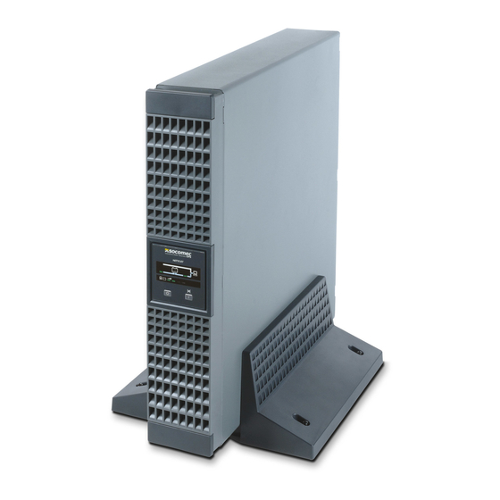
1 1 0 0 - 1 7 0 0 - 2 2 0 0 - 3 3 0 0 V A Installations- und bedienungsanleitung Installation and operating manual Manual de instalación y uso Asennus- ja käyttöohje Manuel d’installation et d’utilisation Manuale di installazione e uso Прирачник...
Page 2
These conditions are subject to Italian law. Disputes shall come under the jurisdiction of Court of Vicenza. SOCOMEC retains the full and exclusive ownership rights over this document. Only a personal right to utilize the document for the application indicated by SOCOMEC is granted to the recipient of such document. All reproduction, modification, dissemination of this document whether in part or whole and by any manner are expressly prohibited except upon Socomec’s express prior written...
For such uses we would advise you to contact SOCOMEC UPS beforehand to confirm the ability of these products to meet the requested level of safety, performance, reliability and compliance with applicable laws, regulations and specifications.
1. SAFETY STANDARDS It is very dangerous to touch any part of the batteries as there is no insulation between the batteries and the mains power source. CAUTION! A battery can present a risk of electrical shock and high short circuit current. •...
2. REQUIREMENTS FOR INSTALLATION Consult the following check list when installing the UPS: 2.1 ENVIRONMENTAL • NETYS RT units are designed for use in enclosed environments. • Position the UPS on a flat and stable surface in a properly ventilated room, well away from heat sources and avoiding direct exposure to sunlight.
Page 11
2. INSTALLATION 2.4.3 Fixing to rack 1. Adapt the length of the tracks to fit the rack. 2. Secure the wing nuts. 3. Fix the track to the rack. 4. Slot in the UPS and tighten the screws. MAX 100 kg MAX 100 kg MAX 100 kg MAX 100 kg...
3. REAR VIEW 1100 VA 1700 VA 3300 VA 2200 VA Legend A Mains input socket (IEC 320) B Fan C UPS PE Output socket (full power) D EPO (Emergency Power Off) E RS232 serial connector (JBUS protocol) F USB socket G Input thermal protection H Slot for optional communication cards Output socket (full power)
4. CONNECTIONS Connection to the mains power supply and to the load(s) must be made using cables of suitable cross section, in accordance with current standards. 1100 VA 1700 VA 3300 VA 2200 VA NETYS RT 1.1-3.3 kVA - Ref.: IOMNETRTXX0B-EN 01...
5. CONNECTION OF BATTERY EXTENSION 5.1 SAFETY WARNINGS • Before connecting the battery extension, check that it is fully compatible with the model of UPS in use. • The use of battery extensions not supplied by the manufacturer is inadvisable. WARNING! There is a risk of explosion if battery modules are replaced with others of incorrect type.
Page 15
ON-OFF ON-OFF 1100 VA 1700 VA 2200 VA 3300 VA Connection of multiple batteries Max EBM with additional charger NRT2-U1100 NRT2-U1700 up to 10 NRT2-U2200 up to 10 NRT2-U3300 up to 10 NETYS RT 1.1-3.3 kVA - Ref.: IOMNETRTXX0B-EN 01...
6. MIMIC PANEL The mimic panel on the front of the UPS provides all essential information on the operating status of the appliance. Legend A LED • Green - Normal operation. • Yellow- Alarm • Red - Load not supplied B LCD display C Scroll button D On button...
7. OPERATING MODES Standby mode. Inverter mode. Battery mode. Bypass mode. Eco mode. 7.1 BATTERY RECHARGE Connect the UPS to the mains voltage for approximately 8 hours to recharge the internal batteries. The UPS can be used even with the batteries not fully charged, though if a power outage should occur, the duration of the backup will be shorter. 7.2 SWITCHING THE UPS ON AND OFF 7.2.1 Switching on with mains present 7.2.1-1...
7. OPERATING MODES 7.2.3 Switching off with mains present 7.2.3-1 7.2.3-2 UPS off • UPS is off but battery remains on charge • Shut down all loads, one at a time. • Switch off mains power to shut down completely. Press up to beep 7.2.4 Buzzer override...
8. VISUAL AND AUDIBLE WARNING SIGNALS Overload warning. Overload with Bypass Overload without Bypass 1 Short every seconds 1 Short every seconds 1 Short every seconds Battery needs replacing. 1 Short every seconds UPS Error Fan failure. Overtemperature. Short-circuit on output. 5 second 5 second continuous...
9. SETTINGS 9.1 SETTING MENU WARNING! Wrong configuration in UPS SETTINGS could damage the load or the batteries. Please refer to after sales support for clarification. 9.1-1 9.1-2 9.1-3 Enter on Setting menu Exit from Setting menu Press up Press up to beep to beep 9.2 SETTINGS...
Page 21
9. SETTINGS Description Value Default Enable the eco mode function on/ off 9.2-7 Set overload value 5/ 10/ 15/..9.2-8 Allow to set the overload alarm level (% of nominal power) 9.2-9 Enable frequency converter mode on/ off 9.2-10 Enable Green function on/ off if enabled, this function switch off the UPS at the following condition:...
10. COMMUNICATION Communication software and accessories are available for monitoring the status of the UPS, with the end in view of optimizing normal operation and ensuring that shutdown at the end of backup time is managed correctly. Applications allow recording of all power outages and any depletion of battery power so as to enable the activation of an automatic procedure for closing programs in ordered sequence and shutting down the system.
Page 23
10. COMMUNICATION 10.6.1 Internal circuit 10.6.1-1 10.6.1-2 Common R1 General alarm R2 No mains R3 Battery low R4 On by-pass R5 Overload R6 Overtemperature CPU Pin GND-R GND-R Input 10.6.1-3 GND-R Common Input GND-C 10.6.2 Standard confi guration relay contact GND-R: Relay ground contact Common: 12~24 V DC General alarm...
Page 24
10. COMMUNICATION 10.6.3 Customized confi guration for relay and/or input contacts Connect Tx to pin 2, Rx to pin 3 and GND-C to pin 5 of the computer’s RS232 port. In Windows, start the Hyper-Terminal application and proceed to open the specified COM port. Set the following properties: Baud rate: 2400, Data Bits: 8, Parity: None, Stop Bit: 1, Flow Control: None.
• Recharge the batteries for a duration of 24 hours at least every 4 weeks during the time the unit remains idle. 11.1 MINOR TROUBLESHOOTING WARNING! If problems should persist or reoccur frequently after following the procedures indicated in this section, contact the SOCOMEC After Sales Service, providing a full description of the current difficulty Problem Possible cause Solution "UPS not powered up...
Page 26
11. MAINTENANCE Problem Possible cause Solution UPS faulty. Contact SOCOMEC After Sales Service. E11, E12, E14, E16, E18, E19. "Overload" icon lit, with Overload. Disconnect non-essential loads. continuous alarm signal. Short cicuit E21 A short circuit is detected on the output...
12. TECHNICAL SPECIFICATIONS Models NRT2-U1100 NRT2-U1700 NRT2-U2200 NRT2-U3300 Nominal Power 1100 VA 1700 VA 2200 VA 3300 VA 900 W 1350 W 1800 W 2700 W Input/Output phases Electrical Specifications - Input Input 1P+N 230 V (175-280 V) up to 100 V @33% load;...
Page 28
Fax. +48 22 825 73 60 info.ups.pl@socomec.com HEAD OFFICE YOUR DISTRIBUTOR SOCOMEC GROUP S.A. SOCOMEC capital 10 816 800€ *IOMNETRTXX0B-EN 01* R.C.S. Strasbourg B 548 500 149 B.P. 60010 - 1, rue de Westhouse F-67235 Benfeld Cedex - FRANCE Tel. +33 3 88 57 41 41 IOMNETRTXX0B-EN 07.2015...
Need help?
Do you have a question about the NRT2-U1100 and is the answer not in the manual?
Questions and answers