
Related Manuals for MSI MS-CF05-SKU1


Summary of Contents for MSI MS-CF05-SKU1
- Page 1 SKU1 (Intel® R680E) SKU2 (Intel® Q670E) MS-CF05 Industrial Computer Board User Guide...
-
Page 2: Table Of Contents
Contents Regulatory Notices ....................... 5 Safety Information ......................8 Specifications ........................ 9 Motherboard Overview ....................12 SKU1 ........................12 SKU2 ........................13 Rear I/O Panel ......................14 SKU1 ........................14 SKU2 ........................14 DisplayPort ......................15 Connector ..................15 RS232/422/485 Serial Port ..................15 VGA Port ......................... - Page 3 M.2 Slots ........................ 24 M2_M1: M.2 Slot (M Key, PCIe 4.0 x4, 2280/ 22110) ................. 24 M2_M2: M.2 Slot (M Key, PCIe 4.0 x4/x2/x1, 2242/ 2280) ..............24 (SKU1 Only) ................25 M2_E1: M.2 Slot (E Key, 2230) (SKU1 Only) ..............25 M2_B1: M.2 Slot (B Key, 2242/ 2280) Connectors ........................
- Page 4 Main ..........................42 Advanced ........................43 Boot..........................50 Security ........................51 Chipset ......................... 59 Power .......................... 60 Save & Exit ........................61 GPIO WDT BKL Programming .................. 62 Abstract ......................... 62 General Purpose IO ....................63 Watchdog Timer ....................65 SMBus Access .......................
-
Page 5: Regulatory Notices
Regulatory Notices FCC-B Radio Frequency Interference Statement This equipment has been tested and found to comply with the limits for a Class B digital device, pursuant to part 15 of the FCC rules. These limits are designed to provide reasonable protection against harmful interference in a residential installation. - Page 6 ∙ Users should contact the local authorized point of collection for recycling and disposing of their end-of-life products. ∙ Visit the MSI website and locate a nearby distributor for further recycling information. ∙ Users may also reach us at gpcontdev@msi.com for information regarding proper Disposal, Take-back, Recycling, and Disassembly of MSI products.
- Page 7 ∙ Reduced solid waste production through take-back policy Copyright and Trademarks Notice Copyright © Micro-Star Int’l Co., Ltd. All rights reserved. The MSI logo used is a registered trademark of Micro-Star Int’l Co., Ltd. All other marks and names mentioned may be trademarks of their respective owners. No warranty as to accuracy or completeness is expressed or implied.
-
Page 8: Safety Information
Safety Information ∙ The components included in this package are prone to damage from electrostatic discharge (ESD). Please adhere to the following instructions to ensure successful computer assembly. ∙ Ensure that all components are securely connected. Loose connections may cause the computer to not recognize a component or fail to start. -
Page 9: Specifications
Specifications Model MS-CF05-SKU1 MS-CF05-SKU2 Dimensions 305(L)mm x 244(W)mm x 1.6(H)mm, ATX-Size ∙ 13th Gen Intel® Raptor Lake-S i9/i7/i5/i3 Pentium®/ Celeron® IOTG Series Processor, Max 125W Processor ∙ 12th Gen Intel® Alder Lake-S i9/i7/i5/i3 Pentium®/ Celeron® IOTG Series Processor, Max 125W Chipset Intel®... - Page 10 Model MS-CF05-SKU1 MS-CF05-SKU2 ∙ 1 x DP 1.4a, up to 4096×2304 @60Hz ∙ 1 x HDMI™ 2.0b, up to 4096x2160 @60Hz ∙ 1 x VGA, up to 1920x1200 @60Hz Graphics ∙ 3 independent display modes supported - DP - HDMI™...
- Page 11 Model MS-CF05-SKU1 MS-CF05-SKU2 ∙ 1 x 24-pin ATX power connector Power ∙ 1 x 4-pin 12V ATX power connector ∙ Windows 10 IoT Enterprise 2021 LTSC (64-bit) OS Support ∙ Windows 11 IoT Enterprise 22H2 LTSC (64-bit) ∙ Linux Kernel 5.xx, Ubuntu 22.04 LTS Pre-scan...
-
Page 12: Motherboard Overview
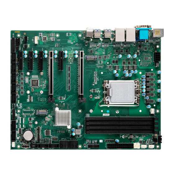
Motherboard Overview SKU1 DIMMB1 DIMMA2 DIMMB2 DIMMA1 JPWR2 CPUFAN1 JPMBUS1 SYSFAN1 SYSFAN2 JSMB1 JI2C1 Rear I/O Panel JPWR1 JUSB2 M2_M1 PCIE1 SATA3_4 PCIE2 SATA1_2 PCIE3 JLAN_LED PCIE4 JFP1 M2_M2 PCIE5 JKBMS1 JUSB1 PCIE6 M2_B1 JSPDIF1 USB1 M2_E1 PCIE7 JAUD1 SYSFAN3 JLPT1 COM6 COM5... -
Page 13: Sku2
SKU2 DIMMB1 DIMMA2 DIMMB2 DIMMA1 JPWR2 CPUFAN1 JPMBUS1 SYSFAN1 SYSFAN2 JSMB1 JI2C1 Rear I/O Panel JPWR1 JUSB2 M2_M1 PCIE1 SATA3_4 SATA1_2 PCIE3 JLAN_LED PCIE4 JFP1 M2_M2 PCIE5 JKBMS1 JUSB1 PCIE6 JSPDIF1 USB1 PCIE7 JAUD1 SYSFAN3 JLPT1 COM6 COM5 COM4 COM3 COM2 JAPS1 JGPIO2... -
Page 14: Rear I/O Panel
Rear I/O Panel SKU1 2.5 GbE RJ-45 LAN Jacks RS232/422/485 Line-Out Serial Port Jack LAN1 LAN2 LAN3 LAN4 DisplayPort VGA Port USB 3.2 Gen 2 Ports Mic-in Jack SKU2 2.5 GbE RJ-45 LAN Jacks RS232/422/485 Line-Out Serial Port Jack LAN1 LAN2 DisplayPort VGA Port... -
Page 15: Displayport
DisplayPort DisplayPort is a digital display interface standard. This connector is used to connect a monitor with DisplayPort inputs. Connector The High-Definition Multimedia Interface (HDMI™) is an all-digital audio/ video interface capable of transmitting uncompressed streams. HDMI™ supports all TV format, including standard, enhanced, or high-definition video, plus multi-channel digital audio on a single cable. -
Page 16: 2.5 Gbe Rj-45 Lan Jacks
2.5 GbE RJ-45 LAN Jacks The standard single RJ45 LAN jack is provided for connection to the Local Area Network (LAN). You can connect a network cable to it. Link/ Activity LED Speed LED Status Description Status Description No link 10/100 Mbps Linked Yellow... - Page 17 Component Contents Component Page CPU Socket Memory DIMM1~2: DDR5 DIMM Slots Storage SATA1_2, 3_4: SATA 3.0 6Gb/s Connectors Expansion Slots PCIE1~7: PCIe Expansion Slots M2_M1: M.2 Slot (M Key, PCIe 4.0 x4, 2280/ 22110) M2_M2: M.2 Slot (M Key, PCIe 4.0 x4/x2/x1, 2242/ 2280) M2_E1: M.2 Slot (E Key, 2230) (SKU1 Only) M2_B1: M.2 Slot (B Key, 2242/ 2280)
-
Page 18: Cpu Socket
CPU Socket Introduction to the LGA1700 CPU The surface of the LGA1700 CPU has four notches and a golden triangle to assist in correctly lining up the CPU for motherboard placement. The golden triangle is the Pin 1 indicator. ⚠ Important Always unplug the power cord from the power outlet before installing or removing ∙... -
Page 19: Cpu & Heatsink Installation
CPU & Heatsink Installation Use appropriate ground straps, gloves and ESD mats to protect yourself from electrostatic discharge (ESD) while installing the processor. ⚠ Important Images are for illustration purposes only; actual parts may vary. ⚽ https://youtu.be/KMf9oIDsGes CPU Socket... -
Page 20: Memory
Memory DIMM1~2: DDR5 DIMM Slots The DIMM slots are intended for memory modules. DIMMA1 DIMMB1 Channel A Channel B DIMMA2 DIMMB2 Recommended Memory Population Quantity of DIMMs DIMMA1 Channel A DIMMA2 DIMMB1 Channel B DIMMB2 **“V” indicates a populated DIMM slot. ** ⚠... -
Page 21: Installing Memory Modules
Installing Memory Modules 1. Open the side clips to unlock the DIMM slot. 2. Insert the DIMM vertically into the slot, ensuring that the off-center notch at the bottom aligns with the slot. 3. Push the DIMM firmly into the slot until it clicks and the side clips automatically close. -
Page 22: Storage
Storage SATA1_2, 3_4: SATA 3.0 6Gb/s Connectors These connectors are SATA 6Gb/s interface port, it can connect to one SATA device. SATA3_4 SATA1_2 ⚠ Important These SATA connectors support hot plug. ∙ Please do not fold the SATA cable at a 90-degree angle. Data loss may result during ∙... -
Page 23: Expansion Slots
Expansion Slots PCIe Slots PCIE1: PCIe 5.0 x16 PCIE2: PCIe 4.0 x4 (SKU1 Only) PCIE3: PCIe 3.0 x4 PCIE4: PCIe 5.0 x16 (Signal share with PCIE1) PCIE5: PCIe 4.0 x4 (Signal share with M2_M2) PCIE6: PCIe 3.0 x4 PCIE7: PCIe 3.0 x4 PCIE1~7: PCIe Expansion Slots The PCI Express (Peripheral Component Interconnect Express) slots support PCIe interface expansion cards. -
Page 24: M.2 Slots
M.2 Slots M2_M1 M2_M2 M2_B1 (SKU1 Only) M2_E1 (SKU1 Only) M2_M1: M.2 Slot (M Key, PCIe 4.0 x4, 2280/ 22110) M2_M2: M.2 Slot (M Key, PCIe 4.0 x4/x2/x1, 2242/ 2280) Please install the M.2 solid-state drive (SSD) into the M.2 slot as shown below. 1. -
Page 25: M2_E1: M.2 Slot (E Key, 2230) (Sku1 Only)
M2_E1: M.2 Slot (E Key, 2230) (SKU1 Only) Please install the Wi-Fi/ Bluetooth card into the M.2 slot as shown below. Feature ∙ Supports PCIe x1 signal. ∙ Supports Intel® AX210 Wi-Fi 6E, Intel® Wireless-AC 9260. CNVI devices are not supported. M2_B1: M.2 Slot (B Key, 2242/ 2280) (SKU1 Only) Please install the WWAN Card/ solid-state drive (SSD) into the M.2 slot as shown... -
Page 26: Connectors
Connectors Power Connectors JPWR2 JPWR1 JPWR1: 24-Pin ATX Power Connector This connector allows you to connect an ATX power supply. +3.3V +3.3V +3.3V -12V PS-ON# JPWR1 PWR OK 5VSB +12V +12V +3.3V JPWR2: 8-Pin ATX 12V Power Connector This connector is used to provide power to SATA devices. P12V P12V JPWR2... -
Page 27: Cooling Connectors
Cooling Connectors CPUFAN1 SYSFAN1 SYSFAN2 SYSFAN3 CPUFAN1, SYSFAN1~3: CPU/ System Fan Connectors The fan power connector supports CPU/ system cooling fans with +12V. When connecting the wire to the connectors, always note that the red wire is the positive and should be connected to the +12V;... -
Page 28: Audio Connectors
Audio Connectors JSPDIF1 JAUD1 JAUD1: Front Audio Connector (Line-out/ MIC-in) This connector allows you to connect front panel audio. MIC_L MIC_R JAUD1 LINE_OUT_R MIC_JD HP_ON No pin LINE_OUT_L LINE_OUT_JD JSPDIF1: S/PDIF Connector This pinheader is used to connect S/PDIF (Sony & Philips Digital Interconnect Format) interface for digital audio transmission. -
Page 29: Usb Connectors
USB Connectors JUSB2 JUSB1 USB1 JUSB2: USB 3.2 Gen 1 Connector This port is backward-compatible with USB 2.0 devices and supports data transfer rate up to 5 Gbps (SuperSpeed). USB_D+ USB 3.2 RX- USB_D- USB 3.2 RX+ USB3_ESD_DN8 USB 3.2 TX- USB 3.2 TX- JUSB2 USB 3.2 TX+... -
Page 30: Jusb1: Usb 2.0 Connector
JUSB1: USB 2.0 Connector This header is ideal for connecting USB devices such as keyboard, mouse, or other USB-compatible devices. USB_D- USB_D- JUSB1 USB_D+ USB_D+ No Pin USB1: USB 2.0 Type-A Connector The USB (Universal Serial Bus) port is for attaching USB devices such as keyboard, mouse, or other USB-compatible devices. -
Page 31: Other Connectors
Other Connectors JFP1: Front Panel Connector This front-panel connector is provided for electrical connection to the front panel switches & LEDs and is compliant with Intel Front Panel I/O Connectivity Design Guide. HDD LED+ POWER LED HDD LED- POWER LED JFP1 RESET SWITCH- POWER SWITCH+... -
Page 32: Jpmbus1: Pmbus Connector
JPMBUS1: PMBus Connector Power Management Bus (PMBus) is a variant of the System Management Bus (SMBus) which is targeted at digital management of power supplies. SMBCLK SMBDATA SMBALERT# JPMBUS1 JSMB1: I2C Connector This connector is provided for users to connect I²C (Inter-Integrated Circuit) interface. SMBCLK JSMB1 SMBDATA... -
Page 33: Com2~6: Serial Port Connectors
COM2~6: Serial Port Connectors This connector is a 16550A high speed communications port that sends/ receives 16 bytes FIFOs. You can attach a serial device to it. SOUT COM2~6 DSR# RTSD CTS# VCC_COM No Pin COM2 COM6 COM5 COM3 COM4 ⚠... - Page 34 SKU1 (Intel® R680E) ∙ COM2 Supports RS-232/ 422/ 485, With Ring/ 0V/ 5V/ 12V (Default set to Ring). ∙ COM3~6 Supports RS-232/ 422/ 485, With 5V/ 12V (Default set to 5V). SKU2 (Intel® Q670E) ∙ COM2 Supports RS-232/ 422/ 485, With Ring/ 0V/ 5V/ 12V (Default set to Ring). ∙...
-
Page 35: Jlan_Led: Lan Led Connector
JLAN_LED: LAN LED Connector This connector is provided for rear panel LAN LEDs. I225_ACT_LINK_1 I225_LED2_LINK#_1 I225_ACT_LINK_2 I225_LED2_LINK#_2 JLAN_LED I225_ACT_LINK_3 I225_LED2_LINK#_3 I225_ACT_LINK_4 I225_LED2_LINK#_4 JKBMS1: PS/2® Keyboard & Mouse Connector This connector is provided to connect a keyboard and a mouse. KBDAT MSDAT JKBMS1 KBCLK... -
Page 36: Jlpt1: Parallel Port Connector
JLPT1: Parallel Port Connector The mainboard provides a 26-pin header for connection to an optional parallel port bracket. The parallel port is a standard printer port that supports Enhanced Parallel Port (EPP) and Extended Capabilities Parallel Port (ECP) mode. RSTB# AFD# PRND0 ERR#... -
Page 37: Jumpers
Jumpers ⚠ Important Avoid adjusting jumpers when the system is on; it will damage the motherboard. J_PCIE_SEL JCOMP1 JCASE1 JCMOS1 JATX1 JCOMP6 JCOMP5 JCOMP4 JCOMP3 JCOMP2 JME_DIS1 Jumper Name Default Setting Description M.2 PCIE Signal Select Jumper J_PCIE_SEL 1-2: M2_M2 enabled (Default) (SKU1 only) 2-3: PCIE5 enabled COM Voltage Select Jumper... - Page 38 Jumper Name Default Setting Description ME Jumper JME_DIS1 1-2: ME enabled (Default) 2-3: ME disabled Clear CMOS Jumper JCMOS1 1-2: Normal (Default) 2-3: Clear CMOS Chassis Intrusion Jumper This connector connects to the chassis intrusion switch cable. If the chassis is opened, the chassis intrusion mechanism JCASE1 Normal...
-
Page 39: Bios Setup
BIOS Setup This chapter provides information on the BIOS Setup program and allows users to configure the system for optimal use. Users may need to run the Setup program when: ∙ An error message appears on the screen at system startup and requests users to run SETUP. - Page 40 Control Keys ← → Select Screen ↑ ↓ Select Item Enter Select Change Value Exit General Help Previous Values Optimized Defaults Save & Reset* Screenshot capture Scroll help area upwards <K> <M> Scroll help area downwards * When you press <F10>, a confirmation window appears and it provides the modification information.
-
Page 41: The Menu Bar
The Menu Bar ▶ Main Use this menu for basic system configurations, such as time, date, etc. ▶ Advanced Use this menu to set up the items of special enhanced features. ▶ Boot Use this menu to specify the priority of boot devices. ▶... -
Page 42: Main
Main HDD Information ∙ RAID (VMD) Disabled: Display HDD information as plugging in status. ∙ RAID (VMD) Enabled: Display "Not Present" only. ▶ System Date This setting allows you to set the system date. Format: <Day> <Month> <Date> <Year>. ▶ System Time This setting allows you to set the system time. -
Page 43: Advanced
Advanced ▶ Full Screen Logo Display This BIOS feature determines if the BIOS should hide the normal POST messages with the motherboard or system manufacturer’s full-screen logo. [Enabled] BIOS will display the full-screen logo during the boot-up sequence, hiding normal POST messages. [Disabled] BIOS will display the normal POST messages, instead of the full- screen logo. - Page 44 ▶ CPU Configuration ▶ Intel Virtualization Technology Enables or disables Intel Virtualization technology. [Enabled] Enables Intel Virtualization technology and allows a platform to run multiple operating systems in independent partitions. The system can function as multiple systems virtually. [Disabled] Disables this function. ▶...
- Page 45 ▶ Intel(R) Speed Shift Technology Intel® Speed Shift Technology is an energy-efficient method that allows frequency control by hardware rather than the OS. [Enabled] When enabled, Intel® Speed Shift Technology is activated. The technology enables the management of processor power consumption via hardware performance state (P-State) transitions.
- Page 46 ▶ Super IO Configuration ▶ Serial Port 1/ 2/ 3/ 4/ 5/ 6, Parallel Port This setting enables or disables the specified serial port. » Change Settings This setting is used to change the address & IRQ settings of the specified serial port. »...
- Page 47 ▶ H/W Monitor (PC Health Status) These items display the current status of all monitored hardware devices/ components such as voltages, temperatures and all fans’ speeds. ▶ Thermal Shutdown This setting determines the behavior of the system when the CPU temperature reaches a predefined threshold.
- Page 48 ▶ PCI/PCIE Device Configuration ▶ Audio Controller This setting enables or disables the detection of the onboard audio controller. ▶ Network Stack Configuration This menu provides Network Stack settings for users to enable network boot (PXE) from BIOS. ▶ Network Stack This menu provides Network Stack settings for users to enable network boot (PXE) from BIOS.
- Page 49 ▶ GPIO Group Configuration ▶ GPO0 ~ GPO7 These settings control the operation mode of the specified GPIO. ▶ PCIE ASPM settings This menu provide settings for PCIe ASPM (Active State Power Management) level for different installed devices. ▶ M2_B1, M2_E1, M2_M1/ PCIE5, PCIE1~4, PCIE6~7 Sets PCI Express ASPM (Active State Power Management) state for power saving.
-
Page 50: Boot
Boot ▶ Boot Option #1-2 This setting allows users to set the sequence of boot devices where BIOS attempts to load the disk operating system. Boot... -
Page 51: Security
Security ▶ Administrator Password Administrator Password controls access to the BIOS Setup utility. ▶ User Password User Password controls access to the system at boot and to the BIOS Setup utility. ▶ Chassis Intrusion Enables or disables recording messages while the chassis is opened. This function is ready for the chassis equips a chassis intrusion jumper(switch). - Page 52 ▶ PCH-FW Configuration This menu allows you to configure settings related to the PCH firmware. Firmware Information These settings show the ME Firmware Version ME Firmware SKU firmware information of the Intel ME (Management ME Firmware Mode ME Firmware Status 1-2 Engine).
- Page 53 ▶ Firmware Update Configuration » ME FW Image Re-Flash Enables or disables the ME Firmware Image Re-flashing. » FW Update Enables or disables the capability to perform a firmware update of the ME locally. ▶ PTT Configuration Intel® Platform Trust Technology (PTT) is a platform functionality for credential storage and key management used by Microsoft Windows.
- Page 54 » HECI Message Check Disable This setting disables message check for BIOS boot path when sending messages. » MBP HOB Skip Setting this option will skip ME’s Memory-Based Protection (MBP) H0B region. » HECI2 Interface Communication This setting Adds/ Removes HECI2 device from PCI space. »...
- Page 55 ▶ Trusted Computing ▶ Security Device Support This item enables or disables BIOS support for security device. When set to [Disable], the OS will not show security device. ▶ SHA256, 384 PCR Bank These settings enables or disables the SHA-1 PCR Bank and SHA256, 384 PCR Bank. ▶...
- Page 56 ▶ Serial Port Console Redirection ▶ Console Redirection Console Redirection operates in host systems that do not have a monitor and keyboard attached. This setting enables or disables the operation of console redirection. When set to [Enabled], BIOS redirects and sends all contents that should be displayed on the screen to the serial COM port for display on the terminal screen.
- Page 57 ▶ Console Redirection Settings (COM1) This option appears when Console Redirection is enabled. » Terminal Type To operate the system’s console redirection, you need a terminal supporting ANSI terminal protocol and a RS-232 null modem cable connected between the host system and terminal(s).
- Page 58 ▶ Secure Boot ▶ Secure Boot Secure Boot function can be enabled only when the Platform Key (PK) is enrolled and running accordingly. ▶ Secure Boot Mode Selects the secure boot mode. This item appears when Secure Boot is enabled. [Standard] The system will automatically load the secure keys from BIOS.
-
Page 59: Chipset
Chipset ▶ DVMT Total Gfx Mem This setting specifies the total graphics memory size for Dynamic Video Memory Technology (DVMT). Chipset... -
Page 60: Power
Power ▶ Restore AC Power Loss This setting specifies whether your system will reboot after a power failure or interrupt occurs. Available settings are: [Power Off] Leaves the computer in the power off state. [Power On] Leaves the computer in the power on state. [Last State] Restores the system to the previous status before power failure or interrupt occurred. -
Page 61: Save & Exit
Save & Exit ▶ Save Changes and Reset Save changes to CMOS and reset the system. ▶ Discard Changes and Exit Abandon all changes and exit the Setup Utility. ▶ Discard Changes Abandon all changes. ▶ Load Optimized Defaults Use this menu to load the default values set by the motherboard manufacturer specifically for optimal performance of the motherboard. -
Page 62: Gpio Wdt Bkl Programming
GPIO WDT BKL Programming This chapter provides WDT (Watch Dog Timer), GPIO (General Purpose Input/ Output) and LVDS Backlight programming guide. Abstract In this section, code examples based on C programming language provided for customer interest. Inportb, Outportb, Inportl and Outportl are basic functions used for access IO ports and defined as following. -
Page 63: General Purpose Io
General Purpose IO 1. General Purposed IO – GPIO/DIO The GPIO port configuration addresses are listed in the following table: Name IO Port IO address Name IO Port IO address N_GPI0 N_GPO0 0x12 Bit 0 0x21 Bit 0 N_GPI1 0x12 Bit 1 N_GPO1 0x21... - Page 64 Example: Set N_GPO1 output “low” val = SMBus_ReadByte (0x6E, 0x21); // Read value from N_GPO1 port through SMBus.. val = val & (~(1<<1)); // Set N_GPO1 address (bit 1) to 0 (output “low”). // Write back to N_GPO1 port through SMBus. SMBus_WriteByte (0x6E, 0x21, val);...
-
Page 65: Watchdog Timer
Watchdog Timer 2. Watchdog Timer – WDT The base address (WDT_BASE) of WDT configuration registers is 0xA10. Set WDT Time Unit val = Inportb (WDT_BASE + 0x05); // Read current WDT setting val = val | 0x08; // minute mode. val = val & 0xF7 if second mode Outportb (WDT_BASE + 0x05, val);... - Page 66 Disable WDT val = Inportb (WDT_BASE + 0x05); // Read current WDT setting val = val & 0xDF; // Disable WDT by set WD_EN (bit 5) to 0. Outportb (WDT_BASE + 0x05, val); // Write back WDT setting. Check WDT Reset Flag If the system has been reset by WDT function, this flag will set to 1.
-
Page 67: Smbus Access
SMBus Access 3. SMBus Access The base address of SMBus must know before access. The relevant bus and device information are as following. #define IO_SC 0xCF8 #define IO_DA 0xCFC #define PCIBASEADDRESS 0x80000000 #define PCI_BUS_NUM #define PCI_DEV_NUM #define PCI_FUN_NUM Get SMBus Base Address int SMBUS_BASE;... - Page 68 Outportb (LOWORD ( ) + 0x02, 0x48); //out Base + 02, 48H SMBUS_BASE mdelay (20); //delay 20ms to let data ready while ((Inportl ( ) & 0x01) != 0); //wait SMBus ready SMBUS_BASE _DATA = Inportb (LOWORD ( ) + 0x05); //input Base + 05 SMBUS_BASE SMBus_WriteByte (char DEVID, char offset, char DATA)
Need help?
Do you have a question about the MS-CF05-SKU1 and is the answer not in the manual?
Questions and answers