Sign In
Upload
Download
Table of Contents
Contents
Add to my manuals
Delete from my manuals
Share
URL of this page:
HTML Link:
Bookmark this page
Add
Manual will be automatically added to "My Manuals"
Print this page
×
Bookmark added
×
Added to my manuals
Manuals
Brands
MSI Manuals
Computer Hardware
MS-S258
User manual
MSI MS-S258 User Manual
Hide thumbs
1
Table Of Contents
2
3
4
5
6
7
8
9
10
11
12
13
14
15
16
17
18
19
20
21
22
23
24
25
26
27
28
29
30
31
32
33
34
35
36
37
38
39
40
41
42
43
44
45
46
47
48
49
50
51
52
53
54
55
page
of
55
Go
/
55
Contents
Table of Contents
Bookmarks
Table of Contents
Table of Contents
Regulatory Notices
Safety Information
System Specifications
System Overview
System LED Indicators
Motherboard Overview
Motherboard Connectors
Power Connectors
Storage Connectors
FPC Connectors
Fan Connectors
Other Connectors and Headers
Motherboard Expansion Slots
Motherboard Jumpers
Onboard Leds
Getting Started
Necessary Tools
Safety Precautions
System Setup
Drive Bay
System Cover
Removing System Cover
CPU & Heatsink
Installing CPU & Heatsink
Memory
Mixing of DIMM Types Within a Channel
Recommended Memory Population
Installing Memory Modules
M.2 M Key
Installing M.2 SSD
Pcie Add-In Card
Installing Pcie Add-In Card
Installing Riser Card Assembly
System Fan
Installing 2U Fan
Installing 2U Fan Cage
Air Duct
Installing Air Duct
Power Supply Unit (PSU)
Installing PSU
Cable Routing
8-Pin to 8-Pin Power Cable
I2C Cable
Slimlinesas 4I to Slimlinesas 4I Cable (for SATA)
Slimlinesas 4I to Slimlinesas 4I Cable (for Nvme)
Slimlinesas 8I to Slimlinesas 4I Cable (for Nvme)
Slide Rail
Disassembling Slide Rail
Installing Inner Rail to System
Retracting Outer Rail Bracket
Attaching Outer Rail Bracket to Rack Frame
Installing System into Rack
Detaching Outer Rail Bracket from Rack Frame
Detaching Inner Rail from System
Advertisement
Quick Links
Download this manual
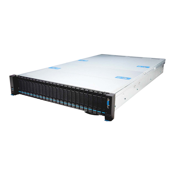
S2201 (2U24)
MS-S258
Server System
User Guide
Table of
Contents
Previous
Page
Next
Page
1
2
3
4
5
Advertisement
Table of Contents
Need help?
Do you have a question about the MS-S258 and is the answer not in the manual?
Ask a question
Questions and answers
Related Manuals for MSI MS-S258
Computer Hardware MSI P6N SLI Series User Manual
Mainboard (108 pages)
Computer Hardware MSI MS-9856 User Manual
Industrial computer board (63 pages)
Computer Hardware MSI CB54G2 User Manual
Wireless 11g cardbus card (47 pages)
Computer Hardware MSI MN54G User Manual
Wireless 11g mini-card (16 pages)
Computer Hardware MSI MS-98C7 Manual
Industrial computer board (54 pages)
Computer Hardware MSI MS-9A95 WindBOX IV Advanced Manual
Slim fanless box pc (51 pages)
Computer Hardware MSI MPG X570S Carbon EK X User Manual
Monoblock (11 pages)
Computer Hardware MSI MAG VAMPIRIC 100R User Manual
(14 pages)
Computer Hardware MSI MS-7846 Manual
(182 pages)
Computer Hardware MSI M-VISION DASHBOARD User Manual
(28 pages)
Computer Hardware MSI MAG CORELIQUID E240 User Manual
Liquid cpu cooler (21 pages)
Computer Hardware MSI 945GT Speedster Manual
Workstation board (109 pages)
MSI MPG Series, MPG CORELIQUID D240 - Liquid CPU Cooler Manual
(article)
Computer Hardware MSI MPG CORELIQUID D360 User Manual
Liquid cpu cooler (24 pages)
Computer Hardware MSI MPG CORELIQUID D240 User Manual
Liquid cpu cooler (23 pages)
Computer Hardware MSI MAG CORELIQUID M360 User Manual
Liquid cpu cooler (22 pages)
This manual is also suitable for:
S2201
2u24
Table of Contents
Print
Rename the bookmark
Delete bookmark?
Delete from my manuals?
Login
Sign In
OR
Sign in with Facebook
Sign in with Google
Upload manual
Upload from disk
Upload from URL


Need help?
Do you have a question about the MS-S258 and is the answer not in the manual?
Questions and answers