
Related Manuals for JVC DOME TYPE CAMERA TK-C676


Summary of Contents for JVC DOME TYPE CAMERA TK-C676
- Page 1 DOME TYPE CAMERA DOME-FARBKAMERA CAMERA DE TYPE DOME CÁMARA TIPO CÚPULA TELECAMERA A DUOMO TK-C676 INSTRUCTIONS LWT0003-001B-CDROM...
-
Page 2: Important Safeguards
IMPORTANT SAFEGUARDS 1. Read all of these instructions. 2. Save these instructions for later use. 3. All warnings on the product and in the operating instructions should be adhered to. 4. Unplug this appliance system from the wall outlet before cleaning. Do not use liquid cleaners or aerosol cleaners. Use a damp cloth for cleaning. -
Page 3: Table Of Contents
WARNING: TO REDUCE THE RISK OF FIRE OR ELECTRIC SHOCK, DO NOT EXPOSE THIS APPLIANCE TO RAIN OR MOISTURE. Thank you for purchsing this product. (These instructions are for TK-C676E) Before beginning to operate this unit, please read the instruction manual carefully in order to make sure that the best possible performance is obtained. -
Page 4: Introduction Features
Introduction Features DSP with a wide dynamic range Even objects that have a large difference in brightness can be monitored clearly. Day/night surveillance When the light is low, the camera pictures can be switched automatically to black and white pictures. The camera is also compatible with IR illumination (wavelength 850 nm to 880 nm). -
Page 5: Precautions For Correct Operation
Precautions for Correct Operation Note on consumable parts The following parts are consumable and should be replaced after a certain number of hours or a count of operations. The service lives given below are only typical values. They may vary depending on the operating environment and conditions. -
Page 6: Controls, Connectors And Indicators
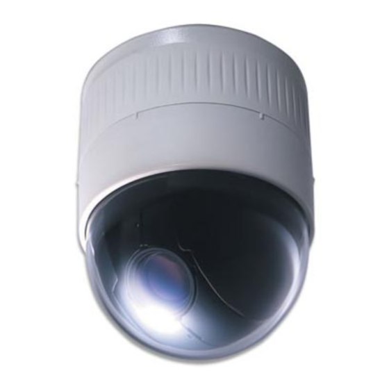
Introduction Controls, Connectors and Indicators Ceiling Mount Cover (Connector side) [VIDEO OUT] Coaxial Cable Connectors Output connector of a composite video signal (1 V(p-p)) with an output impedance of 75 Ω, to be connected to a switcher, etc. [AC ` 24V INPUT] Connector Connect to a 24 V AC power supply. - Page 7 (Setting switch side) Cover For protection against water drips. Slit the rubber cap on this cover and pass the cable through the slits. P. 14 Camera Connector (Female) Connect to , the Male Connector on the camera. Drop Prevention Hook &...
-
Page 8: Connections & Installation A Multi-Drop Communication System
Connections & Installation A Multi-Drop Communication System A system that employs the RM-P2580 as the controller The following figure shows a system that can accommodate up to eight cameras. (64 positions can be preset per camera.) Control signal cable TK-C676 Coaxial cable Camera 1 MACHINE ID: 01... - Page 9 A system that does not employ the RM-P2580 as the controller MEMO Be sure to terminate the control signal cable at both ends. The cables (length of stub) connecting pieces of non-terminated equipment (cameras or controllers) must be as short as possible. If the length of stub is too long, control precision may suffer. ●...
-
Page 10: Point-To-Point Communication System
Connections & Installation Point-to-Point Communication System The following illustration shows a system in which a remote control unit (or a similar piece of equipment) controls a single camera. Video out Control signal cable Switch 4 : OFF (Point to Point) Switch 8 : ON (Terminated 110Ω) Observe the following points when connecting components together:... - Page 11 Use twisted-pair cables for the connections. ●Duplex When the camera is controlled using the full duplex proto- col, set Switch 5 to OFF. Camera RX– TX– Four wires must be connected. For example (connection with an RM-P2580) Camera RX+ C RX–...
-
Page 12: Switch Settings
Connections & Installation Switch Settings Set the switches on the Ceiling Mount before installing the camera. Settings vary according to configuration of the system used. Setting switches ● Switches 1, 2 These switches must be set to OFF. ● DISP (Switch 3) This switch selects whether “MANUAL”... - Page 13 Setting switches ● Machine ID When using a multi-drop system with a remote control unit such as a RM-P2580, the machine IDs need to be set for each camera. Machine IDs are used to identify each of the multiple cam- eras connected to the RM-P2580.
-
Page 14: Cable Connections
Connections & Installation Cable Connections Connect cables to the Ceiling Mount as described below. Make a 90 mm diameter hole in the ceiling. Diameter 90 mm Remove the cover from the Ceiling Mount. Cover Ceiling mount Pass the cables through the cover. Make slits in the rubber cap on the cover as shown in the diagram below. - Page 15 Coaxial cable Connecting a RG-59 coaxial cable. If a RG-11 coaxial cable is used it cannot be con- nected directly to the terminal board. To use such a cable, connect a RG-59 cable to the camera and then connect the RG-11 cable to the RG-59 cable. Treat the extremity of the coaxial cable as shown below before connecting it.
-
Page 16: Attaching The Ceiling Mount
Connections & Installation Attaching the Ceiling Mount To a ceiling slab or channel Ceiling mount Screws Attaching the Camera E-16 Attaching a safety wire. Attach a safety wire to the ceiling mount and to the ceil- ing slab or channel to prevent the unit from dropping. First attach the safety wire to the ceiling mount by pass- ing the wire through the safety wire hole (see the dia- Safety wire hole... - Page 17 Ceiling Mount Lock screw Camera Camera clamping bracket Camera clamping bracket Rotate the camera clockwise. Lock screw Tighten the lock screw. Ensure that the lock screw is loose. The camera cannot be attached properly if the lock screw of the Ceiling Mount is too tight. Fit the camera.
-
Page 18: Setting Up The Camera Using An Rm-P2580 Setup Procedure
Setting Up the Camera Using an RM-P2580 Setup Procedure In systems using an RM-P2580 remote control unit, the menus for use during camera setup can be displayed on the remote control unit. (Please refer to the instructions for RM-P2580.) <Setting the camera menus from an RM-P2580> Power switch MENU button (Rear panel) -
Page 19: Menu Screen Flow
Menu Screen Flow The menu screens are arranged in a hierarchical structure as shown below. Refer to the respective reference pages for the details of each menu. Normal screen S E T U P P O S I T I O N S E T U P . -
Page 20: Camera Function Screen
Setting Up the Camera Using an RM-P2580 CAMERA FUNCTION Screen This screen sets up the functions of the camera itself. Item V. PHASE This adjusts the vertical synchronization to those of other cameras when a selector switch for the synchronizing system on the Ceilling Mount is at LL. (50 Hz power region only.) When it is not set to LL, “---”... -
Page 21: Camera Title/Alarm Screen
CAMERA TITLE/ALARM Screen This screen sets items related to titles and alarms. Item CAM. TITLE EDIT .. This sets the title which is displayed permanently at the bottom left of the picture. This title can be up to 16 characters in length. P. - Page 22 Setting Up the Camera Using an RM-P2580 CAMERA TITLE/ALARM Screen (Continued) Item ALARM INPUT .. (Continued) POLARITY Sets the polarity of the alarm signal inputs. MAKE : Alarm signals are transmitted when point of contact is made. BREAK : Alarm signals are transmitted when contact is broken. MEMO When an item for the B&W is set to the ALARM 1 to 4, it is set to the MAKE mode even if “BREAK”...
-
Page 23: Camera Video Adjustment Screen
CAMERA VIDEO ADJUSTMENT Screen This menu sets the picture signal of the camera, such as the color level and contour enhancement. Item COLOUR LEVEL Sets the color level of the picture signal. To increase : Set a smaller value. To decrease : Set a larger value. - Page 24 Setting Up the Camera Using an RM-P2580 CAMERA ALC/ExDR Screen (Continued) Item AGC MODE Sets the maximum gain of the AGC (Auto Gain Control), which electronically in- creases the gain when the object is under low light conditions. : Turns the AGC off. 10 dB : According to the brightness of the object, gain is increased by up to 10 dB 20 dB...
- Page 25 Item ExDR LEVEL This function sets which section of the object is to be displayed in the easiest-to- view brightness level in the ExDR mode. To make a low-light section of the object easy to view: Increase the level. To make a highlighted section of the object easy to view: Decrease the level. Setting values: –5 to NORMAL to 5 MEMO ●...
-
Page 26: Home Motion Detect Screen
Setting Up the Camera Using an RM-P2580 HOME MOTION DETECT Screen When the camera is in the home position: This screen sets the motion detect function, which outputs an alarm signal when motion is detected in the monitored picture. The alarm signal is output from the alarm output terminal on the terminal board. -
Page 27: Auto Pan/Patrol/Trace Screen
AUTO PAN/PATROL/TRACE Screen This screen sets up the auto pan function for slow panning, the auto patrol function for switching of positions in sequence, and the auto trace function for the reproduction of the results of manual camera operations. Item AUTO PAN MODE Determines movement during auto panning. -
Page 28: Position Function Set Screen
Setting Up the Camera Using an RM-P2580 POSITION FUNCTION SET Screen This screen sets the configurations of functions relating to pictures taken in preset positions. Item POSITION TITLE ... Sets the titles for the 99 preset positions and the home position. Titles can be up to 16 characters in length and are shown in the display. -
Page 29: Private Mask Setup
PRIVATE MASK Setup Use the PRIVATE MASK screen to set up the private mask function, which grays out areas that are not required to be included in the monitored picture. Up to four private masks can be set per screen, and up to eight private masks can be set in total. MENU button SET button REMOTE CONTROL UNIT... -
Page 30: Camera Title Setup
Setting Up the Camera Using an RM-P2580 CAMERA TITLE Setup Use the CAMERA TITLE screen to set the title of each camera. Titles can be up to 16 characters in length and are displayed at the bottom left of the picture. MENU button SET button RM-P2580... -
Page 31: Area Title Setup
AREA TITLE Setup The 360° panning range of the camera can be divided into 16 equally sized areas and an area title can be set for each area. Titles can be of up to 16 characters in length and are displayed in the picture as the camera is panned manually. (Area title display ON/OFF: P. -
Page 32: Alarm Title Setup
Setting Up the Camera Using an RM-P2580 ALARM TITLE Setup Use the ALARM TITLE screen to set the alarm titles to be displayed when an alarm signal is transmitted. Up to 10 alarm titles (ALARM TITLE 1 to 10) can be set and each title can be up to 12 characters in length. MENU button SET button REMOTE CONTROL UNIT... -
Page 33: Home Motion Detect Setup
The areas set to be excluded from the motion detection target area can be confirmed in the DEMONSTRATION screen. The motion detect function is not intended to prevent fire or theft. There- fore, JVC will not assume any liabilities for accidents and damage relat- ed to the use of this function. E-33... -
Page 34: Auto Pan Setup
Setting Up the Camera Using an RM-P2580 AUTO PAN Setup Use the AUTO PAN screen to set the auto pan function, which allows the camera to be revolved slowly in a horizontal direction) The auto pan function has three modes, the RETURN mode for continual movement between two positions, the RIGHT mode for clock-wise rotation and the LEFT mode for counterclockwise rotation. -
Page 35: Auto Patrol Setup
AUTO PATROL Setup Use the AUTO PATROL screen to set the configuration of the auto patrol function, which moves the camera between several positions at a high speed. Patrol positions 1-100 can be set in each of three modes (MODES 1 to 3). It is recommended that these three modes be set the according to the day of the week or the time of day. -
Page 36: Auto Trace Setup
Setting Up the Camera Using an RM-P2580 AUTO TRACE Setup Use the AUTO TRACE screen to set the auto trace function, which stores and reproduces the actions of a manual camera opera- tion (for 30 seconds). MENU button SET button REMOTE CONTROL UNIT RM-P2580 CAMERA... -
Page 37: Position Title Setup
POSITION TITLE Setup Use the POSITION TITLE screen to set the title of each camera position. Each camera position can be given a title of up to 16 characters. MENU button SET button REMOTE CONTROL UNIT RM-P2580 CAMERA POSITION SETUP POWER ALARM MENU... -
Page 38: Other
Other Attaching a Ceiling Flush Mount Bracket (Optional WB-S575) The ceiling flush mount bracket (optional WB-S575) allows the camera to be installed flush with the ceiling surface. In this case the ceiling material should have a thickness of between 5 mm and 31 mm. Mount hole Anchor bolt mount holes Clamping screw... - Page 39 Anchor bolt mount holes Ceiling flush mount bracket attached to the ceiling Ceiling mount Hook Ceiling panel MEMO Both the ceiling flush mount bracket and the drop prevention attachment should be insulated from the ceiling structure. If the ceiling structure is made of a metallic material, an improper insulation with the camera may produce noise in the video. Connect cables to the Ceiling Mount.
-
Page 40: Removing A Ceiling Flush Mount Bracket (Optional Wb-S575)
Other Removing a Ceiling Flush Mount Bracket (Optional WB-S575) Stoppers Push the stopper release lever Release upwards with a screwdriver, etc. label E-40 <Check the release labels thoroughly before removal.> Remove the ceiling panel. Pull the ceiling panel and disengage the two hooks. Remove the camera. -
Page 41: Troubleshooting
Troubleshooting Symptom Is there a problem in the power cable(s) connecting the Picture is not displayed. camera to the power supply unit? (If the power cable(s) are too long or of an inadequate size, the correct voltage may not be supplied due to an increase in cable resistance.) Are cables connected properly to the terminal board on Power cannot be... -
Page 42: Specifications
Other Specifications I Camera Image pickup device : 1/4 type, interline transfer CCD, 752(H) x 582(V) pixels. Sync system : Line Lock, Internal Scanning frequencies : Horizontal 15.625 kHz, Vertical 50 Hz : 50 dB (typical), (AGC OFF, ENHANCE –5) Minimum object : Color mode: illumination... - Page 43 I External dimensions [Unit: mm] (40) ( φ 75) φ 152 I WB-S575 (Ceiling flush mount bracket + Ceiling panel) Ceiling mount position alignment hole 2-12 x 16 long hole Ceiling panel I Ceiling mount hole for WB-S575 Ceiling mount hole (Plate thickness: 5 mm to 31 mm) I Ceiling mount hole Screw...
- Page 44 VICTOR COMPANY OF JAPAN, LIMITED is a registered Trademark owned by VICTOR COMPANY OF JAPAN, LTD. is a registered Trademark in JAPAN, the U.S.A., the U.K. and many other countries. LWT0003-001B-CDROM © 2002 VICTOR COMPANY OF JAPAN, LIMITED...
- Page 45 DOME TYPE CAMERA DOME-FARBKAMERA CAMERA DE TYPE DOME CÁMARA TIPO CÚPULA TELECAMERA A DUOMO TK-C676 INSTRUCTIONS LWT0003-001B-CDROM...
- Page 46 ACHTUNG: ZUR VERMEIDUNG VON FEUER- UND STROMSCHLAGGEFAHR DARF DIESES GERÄT NICHT NÄSSE ODER FEUCHTIGKEIT AUSGESETZT WERDEN. Wir bedanken uns für den Kauf dieses Produktes. (Dieses Handbuch ist für TK-C676E bestimmt.) Bitte lesen Sie dieses Handbuch vor dem Gebrauch dieses Produktes sorgfältig, um einwandfreien Betrieb und eine optimale Nutzung zu gewährleisten.
-
Page 47: Einleitung Besondere Merkmale
Einleitung Besondere Merkmale DSP mit großem Dynamikumfang Die Kamera bildet selbst Objekte mit hohen Helligkeitsunterschieden klar ab. Tag-und-Nacht-Überwachung Bei geringer Umgebungshelligkeit kann die Kamera automatisch auf den Schwarzweißmodus umgeschaltet werden. Die Kamera ist zudem Infrarotsignal-kompatibel (Wellenlänge von 850 nm bis 880 nm). Selektive Maskenfunktion Mittels der Maskenfunktionen können Segmente innerhalb des Kamera-Überwachungsbereichs, die nicht gezeigt werden sollen, abgeschirmt werden. -
Page 48: Vorsichtsmaßregeln Zur Einwandfreien Handhabung
Vorsichtsmaßregeln zur einwandfreien Handhabung Hinweise zu Bauteilen, die Abnutzung unterliegen Die nachfolgend aufgelisteten Bauteile sind Abnutzungs- einwirkungen ausgesetzt und müssen nach Ablauf ihrer Nutzungsdauer oder Nutzungshäufigkeit ausgetauscht werden. Je nach Umgebungs- und Anwendungsbedingungen kann der Zeitraum bis zur vollständigen Abnutzung schwanken. Beachten Sie, dass der Austausch von Abnutzungsbauteilen kostenpflichtig ist, selbst wenn solche Bauteile vor Ablauf der Garantiezeit ausgetauscht werden. -
Page 49: Bedienungselemente, Anschlüsse Und Anzeigen
Einleitung Bedienungselemente, Anschlüsse und Anzeigen Deckenhalter Schutzgehäuse (Anschlussseite) [VIDEO OUT] Koaxialbuchse Ausgangsbuchse für VBS-Signal (1 Vss) mit einer Aus- gangsimpedanz von 75 Ω. Mit einem Sequenzerschalter etc. verbinden. [AC ` 24 V INPUT] Stromeingangsbuchse Hier 24 Volt Wechselstrom anlegen. Schutzgehäusemarkierung Beim Anbringen des Schutzgehäuses zur abschließenden Ausrichtung verwenden. - Page 50 (Einstellschalterseite) Schutzgehäuse Zum Schutz gegen Wassertropfen. Die Gummikappe auf- schneiden und das Kabel durch die Schlitze führen. S. 14 Kamerabuchse Mit dem Steckverbinder der Kamera verbinden. Haken für Sicherungsdraht & Den Sicherungsdraht an diesem Haken abringen, um die Kamera gegen ein Herunterfallen zu schützen. Montageöffnungen (x 4) Die Kamera an einer Decke oder einer Versenkeinbau- halterung (optionales Zubehör) unter Verwendung dieser...
-
Page 51: Anschlussherstellung Und Installation
Anschlussherstellung & Installation Mehrfachkamera-System System einschließlich Steuerpult RM-P2580 Die folgende Abbildung zeigt eine Konfiguration für bis zu acht Kameras (bis zu 64 Positionen je Kamera). Steuersignalkabel TK-C676 Koaxialkabel Kamera 1 24 V Wechselstromversorung MACHINE ID: 01 Schalter 8: OFF (RX TERM) TK-C676 Kamera 2 24 V Wechselstromversorung... - Page 52 System mit einer anderen Steuereinheit als Steuerpult RM-P2580 MEMO Für das Steuersignalkabel ist eine beidseitige Abschlussschaltung erforderlich. Die kürzestmögliche Kabellänge für die Abstand- srohre der Geräte ohne Abschlussschaltung (Kameras und der Fernsteuereinheit) wählen. Bei zu großer Kabellänge kann es zu Steuerbeeinträchtigungen kommen.
-
Page 53: Einzelkamera-System
Anschlussherstellung und Installation Einzelkamera-System Das folgende Beispiel zeigt ein System mit einer Kamera und einer geeigneten Steuereinheit (Fernbedienung). Videoausgang Steuersignalkabel Schalter 4 : OFF (Einzelbetrieb) Schalter 8: ON (mit 110 Ω abgeschlossen) Bitte vor der Systemanschlussherstellung beachten: • Vor der Anschlussherstellung alle Geräte ausschalten. •... - Page 54 Zweifach verdrillte Kabel verwenden. ●Duplex Wenn die Kamera im vollen Duplex-Protokoll gesteuert wird, muss Schalter 5 auf OFF gestellt werden. Kamera RX– TX– Zum Anschluss werden vier Leiter benötigt. Anschlussbeispiel (für Steuerpult RM-P2580) Kamera RX+ C RX– D TX+ A TX–...
-
Page 55: Schaltereinstellungen
Anschlussherstellung und Installation Schaltereinstellungen Die Schaltereinstellungen am Deckenhalter müssen vor der Installation der Kamera vorgenommen werden. Die Einstellungen schwanken je nach Systemkonfiguration. Erforderliche Schaltereinstellungen ● Schalter 1, 2 Diese Schalter müssen auf “OFF” gestellt sein. ● DISP (Schalter 3) Mit diesem Schalter kann die Anzeigefunktion für die Monitormeldung “MANUAL”... - Page 56 Erforderliche Schaltereinstellungen ● Geräte-ID Wird diese Kamera in einem Mehrfachkamera-System einschließlich Steuereinheit (wie RM-P2580) eingesetzt, muss jeder Kamera eine Geräte-ID-Nummer zugewiesen werden. Dies ermöglicht die selektive Steuerung für die an RM-P2580 angeschlossenen Kameras. Die Geräte-ID-Nummer muss jeweils mit der Nummer der VIDEO INPUT-Anschlüsse von RM-P2580 übereinstimmen.
-
Page 57: Kabelanschlüsse
Anschlussherstellung und Installation Kabelanschlüsse An der Einbauposition muss eine runde. Einbauöffnung mit 90 mm Durchmesser hergestellt werden. 90 mm Durchmesser Das Schutzgehäuse von dem Deckenhalter abnehmen. Schutzgehäuse Deckenhalter Die Kabel durch die Öffnung des Schutz- gehäuses führen. Wie in der nachfolgenden Abbildung gezeigt zwei Schl- itze in die Gummikappe schneiden und die von der Decke kommenden Kabel durch diese aufgeschnittene Gummi- kappe führen. - Page 58 Koaxialkabel Bei Verwendung eines RG-59 Koaxialkabels. Ein RG-11 Koaxialkabel kann nicht direkt angeschlossen werden. Soll ein solches Kabel verwendet werden, ein RG-59 Kabel an die Kamera anschließen und mit dem RG-11 Kabel verbinden. Das Koaxialkabelende muss wie nachfolgend gezeigt vorbereitet werden. Die Drahtummantelung nach hinten stülpen und mit Isolierband sichern, damit diese sich nicht lösen und kein Kurzschluss entstehen kann.
-
Page 59: Installation Der Kamera
Anschlussherstellung & Installation Installation des Deckenhalters An Strebe oder Träger Deckenhalter Schrauben Installation der Kamera G-16 Einen Sicherungsdraht anbringen. Einen Sicherungsdraht an dem Deckenhalter und einem Deckenträger etc. anbringen, um ein Herunterfallen des Halters zu verhindern. Zuerst den Sicherungsdraht durch die Öse des Halters führen (siehe die linke Abbildung). - Page 60 Deckenhalter Halteschraube Kamera Kameraklemmbügel Kameraklemmbügel Die Kamera im Uhrzeigersinn drehen. Halteschraube Die Halteschraube festziehen. Sicherstellen, dass die Halteschraube gelöst ist. Die Kamera kann nicht am Deckenhalter angebracht werden, wenn die Halteschraube bereits festgezogen ist. Die Kamera anpassen. Die Position des Kameraklemmbügels und der Halte- schraube überprüfen und die Kamera am Deckenhalter anpassen.
-
Page 61: Kamera-Setup Mit Steuerpult Rm-P2580 Setup-Bedienschritte
Kamera-Setup mit Steuerpult RM-P2580 Setup-Bedienschritte Bei der Verwendung von Steuerpult RM-P2580 können die zum Kamera-Setup erforderlichen Menüs auf dem angeschlossenen Monitor dargestellt werden. (Bitte beziehen Sie sich auf die zum Steuerpult RM-P2580 gehörige Bedienungsanleitung.) <Kameramenüeinstellungen mit RM-P2580> Hauptschalter MENU-Taste (Rückseite) SET-Taste POWER-LED REMOTE CONTROL UNIT... -
Page 62: Camera Function-Men
Menüaufbau Die Menüs sind wie unten gezeigt hierarchisch strukturiert. Die einzelnen Menüeinträge werden jeweils auf der angezeigten Seite erläutert. Normale Bildschirmanzeige S E T U P P O S I T I O N S E T U P . . C A M E R A . -
Page 63: Camera Function-Menü
Kamera-Setup mit Steuerpult RM-P2580 CAMERA FUNCTION-Menü Dieses Menü dient zur Einstellung von Kamerafunktionen. Eintrag V.PHASE Zum Abgleich des V-Syncsignals auf weitere zum System gehörigen Kameras, wenn der am Deckenhalter Syncwahlschalter auf LL gestellt ist. (Nur für Stromnetze mit 50 Hz.) Wenn der Einstellstatus LL nicht vorliegt, erscheint die Anzeige “- - -”... -
Page 64: Camera Title/Alarm-Menü
CAMERA TITLE/ALARM-Menü Dieses Menü dient zur Einstellung von Titel- und Alarmfunktionen. Eintrag CAM. TITLE EDIT .. Dient zur Erstellung des ständig links unten im Bild eingeblendeten Titels. Ein Titel darf bis zu 16 alphanummerische Zeichen enthalten. S. 30, “CAMERA TITLE-Einstellungen” AREA TITLE Der Schwenkbereich von 360°... - Page 65 Kamera-Setup mit Steuerpult RM-P2580 CAMERA TITLE/ALARM-Menü (FORTS.) Eintrag ALARM INPUT .. (Fortsetzung) POLARITY Dient zur Einstellung der Polarität des Alarmeingangssignals. MAKE : Alarmsignal liegt bei geschlossenem Kontakt vor. BREAK : Alarmsignal liegt bei offenem Kontakt vor. MEMO Wird ein Eintrag im B&W-Modus für Alarm 1 bis 4 eingestellt, wird der MAKE-Modus gewählt, selbst wenn “BREAK”...
-
Page 66: Camera Video Adjustment-Menü
CAMERA VIDEO ADJUSTMENT-Menü Dieses Menü dient zur Einstellung von Kamerafunktionen, wie Farbpegel, Konturenverstärkung etc. Eintrag COLOUR LEVEL Dient zur Einstellung des Farbpegels. Pegelerhöhung Pegeleabsenkung Verfügbare Einstelloptionen: –5 bis NORMAL bis 5. ENHANCE LEVEL Dient zur Einstellung der Konturenverstärkung, d.h. zur Einstellung der bevorzugten Bildschärfe. - Page 67 Kamera-Setup mit Steuerpult RM-P2580 CAMERA ALC/EXDR-Menü (FORTS.) Eintrag AGC MODE Dient zur Einstellung des maximalen AGC-Pegels (Auto Gain Control) zur elektronischen Pegelanhebung bei geringer Umgebungshelligkeit. : Deaktivierter AGC-Modus. 10 dB : Je nach Umgebungshelligkeit erfolgt die Pegelanhebung um bis zu 10 dB. 20 dB : Je nach Umgebungshelligkeit erfolgt die Pegelanhebung um bis zu 20 dB.
- Page 68 Eintrag ExDR LEVEL Dient zur Einstellung des Helligkeitspegels im ExDR-Modus, so dass vom Benutzer zu definierenden Objektbereiche in der bestmöglichen Erkennbarkeit gezeigt werden können. Wenn ein dunkler Objektbereich deutlich erkennbar sein soll: Den Pegel erhöhen. Wenn ein heller Objektbereich deutlich erkennbar sein soll: Den Pegel verringern. Verfügbare Einstelloptionen : –5 bis NORMAL bis 5 MEMO ●...
-
Page 69: Home Motion Detect-Menü
Kamera-Setup mit Steuerpult RM-P2580 HOME MOTION DETECT-Menü Wenn die Kamera auf die Grundposition eingestellt ist. Dieses Menü dient zur Einstellung der Bewegungssensorfunktionen mit automatischer Alarmabgabe bei erfasster Objektbewegung im überwachten Bildbereich. Eintrag MODE Dient zur Aktivierung/Deaktivierung der Bewegungssensorfunktion. OFF : Deaktivierte Funktion. ON : Aktivierte Funktion. -
Page 70: Auto/Pan/Patrol/Trace-Menü
AUTO PAN/PATROL/TRACE-Menü Dieses Menü dient zur Einstellung der automatischen Schwenkfunktion (langsames Schwenken), der automatischen Spähfunktion (Positionswechsel in Folge) und der automatischen Lernfunktion zur Reproduktion der Ergebnisse der manuellen Kameraeinstellungen. Eintrag AUTO PAN MODE Dient zur Einstellung der automatischen Schwenkausführung. RETURN : Kontinuierlicher Rückstartposition. -
Page 71: Position Funktion Set-Menü
Kamera-Setup mit Steuerpult RM-P2580 POSITION FUNCTION SET-Menü Dieses Menü dient zur Einstellung der Kamerafunktionen, die für die vorbestimmten Positionen gelten. Eintrag POSITION TITLE ... Dient zur Titeleingabe für 99 vorbestimmte Kamerapositionen und die Grundposition. Titel dürfen bis zu 16 alphanummerische Zeichen enthalten. S. -
Page 72: Private Mask-Einstellungen
PRIVATE MASK-Einstellungen Unter Bezugnahme auf das PRIVATE MASK-Menü kann benutzerseitig bestimmt werden, welcher Bildbereich bei der Bildüberwachung durch eine Maske (graues Feld) abgeschirmt werden soll. Für einen Bildschirm können bis zu vier Masken eingestellt werden. Insgesamt sind bis zu 8 Masken verfügbar. MENU-Taste SET-Taste REMOTE CONTROL UNIT... -
Page 73: Camera Title-Einstellungen
Kamera-Setup mit Steuerpult RM-P2580 CAMERA TITLE-Einstellungen Das CAMERA TITLE-Menü dient dazu, den einzelnen Kameras einen Titel zuzuweisen. Titel dürfen bis zu 16 alphanummerische Zeichen enthalten und werden links unten im Bild eingeblendet. MENU-Taste SET-Taste RM-P2580 REMOTE CONTROL UNIT CAMERA POSITION SETUP POWER ALARM... -
Page 74: Area Title-Einstellungen
AREA TITLE-Einstellungen Der 360°-Schwenkradius der Kamera kann in 16 Schwenksegmente unterteilt werden, wobei jedem Schwenksegment ein Titel zugewiesen werden kann. Titel dürfen bis zu 16 alphanummerische Zeichen enthalten und werden im Bild eingeblendet, wenn die Kamera manuell geschwenkt wird. (Aktivierung/Deaktivierung der Titelfunktion: ( S. -
Page 75: Alarm Title-Einstellungen
Kamera-Setup mit Steuerpult RM-P2580 ALARM TITLE-Einstellungen Das ALARM TITLE-Menü dient zur Eingabe von Alarmtiteln; Alarmtitel werden bei Vorliegen eines Alarmsignals gezeigt. Bis zu 10 Alarmtitel (ALARM TITLE 1 bis 10) können eingegeben werden, wobei jeder Titel bis zu 12 alphanummerische Zeichen enthalten darf. -
Page 76: Home Motion Detect-Einstellungen
Die Rasterfelder stellen Bezugsangaben dar. Der Abschirmeffekt muss bei normaler Bildwiedergabe überprüft werden. Die eingestellten Abschirmbereiche können im Vorführmodus (DEMONSTRA- TION-Menü) überprüft werden. Die Bewegungssensorfunktion ist nicht zur Feuer- und Diebstahlsvor- beugung vorgesehen. JVC übernimmt keinerlei Haftung für Unfälle und Schäden, die bei Verwendung dieser Funktion auftreten. G-33... -
Page 77: Auto Pan-Einstellungen
Kamera-Setup mit Steuerpult RM-P2580 AUTO PAN-Einstellungen Das AUTO PAN-Menü dient zur Einstellung für den automatischen Schwenkmodus (langsames Schwenken der Kamera). Im automatischen Schwenkmodus sind drei Funktionen verfügbar: RETURN-Modus: kontinuierlicher Schwenkmodus zwischen zwei vorbestimmten Positionen; RIGHT-Modus: Drehung im Uhrzeigersinn; LEFT-Modus: Drehung gegen den Uhrzeigersinn. Langsames Schwenken MENU-Taste... -
Page 78: Auto Patrol-Einstellungen
AUTO PATROL-Einstellungen Das AUTO PATROL-Menü dient zur Konfiguration der automatischen Spähfunktion, bei der die Kameraausrichtung schnell zwischen verschiedenen vorbestimmten Positionen wechselt. Für jeden der drei Modi (MODE 1 bis 3) können die Spähpositionen 1 bis 100 eingegeben werden. Wir empfehlen, Einstellungen für diese drei Modi in Abhängigkeit vom Wochentag und/oder der Tageszeit vorzunehmen (z.B. -
Page 79: Auto Trace-Einstellungen
Kamera-Setup mit Steuerpult RM-P2580 AUTO TRACE-Einstellungen Das AUTO TRACE-Menü dient zur Einstellung der automatischen Lernfunktion zur Speicherung und Reproduktion von manuellen Bedienschritte (für bis zu 30 Sekunden). MENU-Taste SET-Taste REMOTE CONTROL UNIT RM-P2580 CAMERA POSITION SETUP POWER ALARM MENU AUTO KEY LOCK Nummerische Tastatur CAMERA-Tasten... -
Page 80: Position Title-Einstellungen
POSITION TITLE-Einstellungen Das POSITION TITLE-Menü dient zur Titeleingabe für die Kameraposition. Jeder Kameraposition kann ein Titel mit bis zu 16 alphanummerischen Zeichen zugewiesen werden. MENU-Taste SET-Taste REMOTE CONTROL UNIT RM-P2580 CAMERA POSITION SETUP POWER Nummerische ALARM MENU AUTO KEY LOCK Tastatur CAMERA-Tasten LENS... -
Page 81: Sonstiges
Sonstiges Den Versenkeinbauhalter (optionales Zubehör WB-S575) anbringen Der Versenkeinbauhalter (optionales Zubehör WB-S575) ermöglicht den versenkten Einbau in einer Zwischendecke etc. mit einer zulässigen Dicke zwischen 5 mm und 31 mm. Einbauöffnung Bohrungen für Verankerungsschrauben Bügelschraube Lösen Bügelschraube Bügelschraube Halteschrauben (x4) Bügelschraube Anschläge Fassung für Verankerungsschraube... - Page 82 Bohrungen für Verankerungsschrauben Vollständig in der Zwischendecke installierter Versenkeinbauhalter Deckenhalter Haken Deckenringblende MEMO Sowohl der Deckenhalter als auch der Sicherungsdraht sollten so befestigt werden, dass sie von dem Haltepunkt der Decke isoliert sind. Wenn der Deckenhalter in eine Decke aus einem metallischen Material ohne ausreichende Isolation eingebaut wird, können Bildstörungen bei der Kamera verursacht werden.
-
Page 83: Den Versenkeinbauhalter (Optionales Zubehör Wb-S575) Entfernen
Sonstiges Den Versenkeinbauhalter (optionales Zubehör WB-S575) entfernen Anschläge Den Ausklinkriegel mit einem Ausklinkmarkierung Schraubendreher etc. nach oben drücken. G-40 <Vor dem Ausbau die Ausklinkmarkierungen sorgfältig überprüfen> Die Deckenringblende entfernen. An der Ringblende ziehen und die beiden Haken entfernen. Die Kamera deinstallieren. In umgekehrter Reihenfolge wie bei der Installation vorgehen. -
Page 84: Fehlersuche
Fehlersuche Störung Mögliche Ursache (Beschreibung) Liegt eine einwandfreie Anschlussverbindung zwischen Kein Kamerabildsignal. Stromquelle und Kamera vor? (Bei zu langem Kabel oder ungeeignetem Kabelquerschnitt kann sich der Kabelwiderstand ggf. erhöhen, so dass die erforderliche Nennspannung nicht erzielt wird.) Sind die Kabel einwandfrei an dem Deckenhalter Keine Kameraeinschaltung. -
Page 85: Technische Daten
Sonstiges Technische Daten I Kamera Bildwandler : 1/4 Zoll. Interline Transfer-CCD mit 752 (H) x 582 (V) Pixeln. Syncsignal : Internes netzverkoppeltes Syncsignal Austastfrequenz : H : 15,625 Hz V : 50 Hz Signal/Rausch-Abstand : 50 dB (typisch), (AGC OFF, ENHANCE –5) Mindestbeleuchtung : Farbmodus: 1,8 lx... - Page 86 I Außenabmessungen [Einheit: mm] (40) ( φ 75) φ 152 I WB-S575 (Versenkeinbauhalter + Deckenringblende) Einbaumarkierung für Deckenhalter Ovale Bohrung (2-12 x 16) für Verankerungsschraube Deckenringblende I Einbauöffnung für WB-S575 Einbauöffnung (für Zwischendecken mit 5 mm bis 31 mm Stärke) I Deckeneinbauöffnung Schrauben positionen...
- Page 87 VICTOR COMPANY OF JAPAN, LIMITED is a registered Trademark owned by VICTOR COMPANY OF JAPAN, LTD. is a registered Trademark in JAPAN, the U.S.A., the U.K. and many other countries. LWT0003-001B-CDROM © 2002 VICTOR COMPANY OF JAPAN, LIMITED...
- Page 88 DOME TYPE CAMERA DOME-FARBKAMERA CAMERA DE TYPE DOME CÁMARA TIPO CÚPULA TELECAMERA A DUOMO TK-C676 INSTRUCTIONS LWT0003-001B-CDROM...
- Page 89 AVERTISSEMENT: POUR REDUIRE LES RISQUES D’INCENDIE OU D’ELECTROCUTION, NE PAS EXPOSER L’APPAREIL A LA PLUIE OU A L’HUMIDITE. Nous vous remercions pour l’achat de ce produit. (Ce mode d’emploi concerne le TK-C676E.) Avant de commencer à faire fonctionner cet appareil, veuillez lire attentivement le mode d’emploi afin d’obtenir la meilleure per- formance possible.
-
Page 90: Introduction
Introduction Caractéristiques DSP avec plage dynamique large Même les objets à différence de luminosité importante peuvent être surveillés clairement. Surveillance de jour/nuit Quand l’éclairage est faible, les images de la caméra peuvent être commutées automatiquement au noir et blanc. La caméra est aussi compatible avec l’éclairage IR longueur d’onde de 850 à 880 nm). Masquage personnalisé... -
Page 91: Précautions Pour Le Fonctionnement Correct
Précautions pour le fonctionnement correct Remarque sur les produits d’usure Les pièces suivantes sont des pièces d’usure et doivent être rem- placées après un certain nombre d’heures ou un comptage d’opérations. Les vies de service indiquées ci-dessous sont seule- ment des valeurs typiques. Elles peuvent varier selon l’environnement et les conditions de fonctionnement. -
Page 92: Commandes, Connecteurs Et Indicateurs
Introduction Commandes, connecteurs et indicateurs Montage au plafond Couvercle (côté connecteurs) Connecteurs de câble coaxial [VIDEO OUT] Connecteur de sortie de signal vidéo composite (1 V(c-c)) à impédance de sortie de 75 Ω, à raccorder à un commu- tateur etc. Connecteur [AC ` 24V INPUT] Le raccorder à... - Page 93 (côté commutateur de réglage) ouvercle Pour la protection contre les dégouttements d’eau. Fendre le chapeau en caoutchouc sur ce couvercle et passer le câble par ses fentes. P. 14 Connecteur de caméra (femelle) Le raccorder au connecteur mâle Crochet antichute &...
-
Page 94: Raccordements Et Installation Système De Communication Multi-Drop
Raccordements et installation Système de communication Multi-Drop Un système employant le RM-P2580 comme contrôleur L’illustration suivante montre un système capable de loger huit caméras. (64 positions peuvent être préréglées par caméra.) Câble de signal de contrôle TK-C676 Câble coaxial Caméra 1 Alimentation secteur 24 V MACHINE ID: 01 Schalter 8: OFF... - Page 95 Système n’utilisant pas le RM-P2580 comme contrôleur MEMO Ne pas oublier de terminer le câble de signal de contrôle aux deux extrémités. Les éléments de raccordement des câbles (longueur de tronçon) des équipements (caméras ou contrôleurs) doivent être aussi courts que possible. Si le tronçon est trop long, la précision du contrôle peut être affectée.
-
Page 96: Système De Communication Point À Point
Raccordements et installation Système de communication point à point L’illustration suivante montre un système dans lequel la télécommande (ou un équipement similaire) contrôle une seule caméra. Sortie vidéo Câble du signal de contrôle Commutateur 4 : OFF (point à point) Commutateur 8: ON (terminé... - Page 97 Utiliser un câble à paire torsadée pour les raccordements. ●Duplex Quand la caméra est contrôlée en utilisant un protocole entièrement duplex, régler le commutateur 5 sur OFF. Caméra RX– TX– Quatre fils doivent être raccordés. Par exemple (raccordement avec un RM-2580) Caméra RX+ C RX–...
-
Page 98: Réglages Des Commutateurs
Raccordements et installation Réglages des commutateurs Régler les commutateurs sur la monture de plafond avant d’installer la caméra. Les réglages varient selon la configuration de système utilisée. Réglage des commutateurs ● Commutateurs 1, 2 Ces commutateurs doivent être réglés sur OFF. ●... - Page 99 Réglage des sélecteurs ● ID machine Dans un système multipoint avec télécommande telle que RM-P2580, l’ID machine doit être réglé pour chaque caméra. Les ID machine sont utilisés pour identifier chacune des caméras raccordées au RM-P2580. Régler les ID machine selon les numéros de borne VIDEO INPUT correspondants sur le RM-P2580.
-
Page 100: Raccordement Des Câbles
Raccordements et installation Raccordement des câbles Raccorder les câbles à la monture de plafond comme indiqué ci-dessous. Percer un trou de 90 mm de diamètre dans le plafond. Diamètre 90 mm Retirer le couvercle de la monture de plafond. Couvercle Monture de plafond Passer les câbles dans le couvercle. - Page 101 Câble coaxial Raccordement d’un câble coaxial RG-59. Si un câble coaxial RG-11 est utilisé, il ne peut pas être raccordé directement à une plaque à bornes. Pour uti- liser un tel câble, raccorder un câble RG-59 à la caméra, puis raccorder le câble RG-11 au câble RG-59. Traiter l’extrémité...
-
Page 102: Fixation De La Monture De Plafond
Raccordements et installation Fixation de la monture de plafond A une plaque ou cannelure de plafond Garniture en caoutchouc Monture de (Quatre de chaque côté) plafond Fixation de la caméra F-16 Fixer un fil de sécurité. Fixer un fil de sécurité à la monture de plafond et à la plaque ou cannelure du plafond pour éviter la chute de l’appareil. - Page 103 Monture de plafond Vis de blocage Caméra Support de calage de caméra Support de calage de caméra Tourner la caméra dans le sens horaire. Vis de blocage Serrer la vis de blocage. Vérifier que la vis de blocage est desserrée. La caméra ne peut pas être fixée correctement si la vis de blocage de la monture de plafond est trop serrée.
-
Page 104: Implantation De La Caméra Avec Le Rm-P2580 Procédure D'implantation
Implantation de la caméra avec le RM-P2580 Procédure d’implantation Dans les systèmes utilisant la télécommande RM-P2580, les menus à utiliser pendant l’implantation de la caméra peuvent être affichés sur la télécommande. (Voir le mode d’emploi du RM-P2580.) <Réglage des menus de la caméra à un RM-P2580> Interrupteur d’alimentation Touche MENU (panneau arrière) -
Page 105: Flux Des Écrans De Menu
Flux des écrans de menu Les écrans de menu sont arrangés en structure hiérarchique comme indiqué ci-dessous. Voir les pages de référence respectives pour les détails sur chaque menu. Ecran normal S E T U P P O S I T I O N S E T U P . -
Page 106: Ecran Camera Function
Implantation de la caméra avec un RM-P2580 ECRAN CAMERA FUNCTION Cet écran implante les fonctions de la caméra elle-même. Poste V. PHASE Ajuste la synchronisation verticale à celle des autres caméras quand le sélecteur pour le système de synchronisation sur la monture de plafond est à LL. (régions à puissance 50 Hz seulement). -
Page 107: Ecran Camera Title/Alarm
ECRAN CAMERA TITLE/ALARM Cet écran règle les postes liés aux titres et alarmes. Poste CAM. TITLE EDIT .. Règle le titre qui est affiché en permanence en bas à gauche de l’image. Ce titre peut avoir un maximum de 16 caractères. P. - Page 108 Implantation de la caméra avec un RM-P2580 Ecran CAMERA TITLE/ALARM (suite) Poste ALARM INPUT .. (Continued) POLARITY Règle la polarité des entrées de signal d’alarme. MAKE : Les signaux d’alarme sont transmis quand un point de contact est fait. BREAK : Les signaux d’alarme sont transmis quand un contact est rompu. MEMO Quand un poste pour le B&W est réglé...
-
Page 109: Ecran Camera Video Adjustment
Ecran CAMERA VIDEO ADJUSTMENT Ce menu règle le signal d’image de la caméra, par exemple le niveau de la couleur et le rehaussement du contour. Poste COLOUR LEVEL Règle le niveau de la couleur du signal d’image. Pour l’augmenter Pour le réduire Valeurs de réglage : –5 à... - Page 110 Implantation de la caméra avec un RM-P2580 Ecran CAMERA ALC/ExADR (suite) Poste AGC MODE Règle le gain maximum de l’AGC (commande automatique du gain), qui augmente électroniquement le gain quand l’objet est sous faible éclairage. : Désactive l’AGC. 10 dB : Le gain est augmenté...
- Page 111 Poste ExDR LEVEL Règle quelle section de l’objet doit être affichée au niveau de luminosité le plus facile à visualiser en mode ExDR. Pour rendre une section faiblement éclairée de l’objet facile à visualiser: Augmenter le niveau. Pour rendre une section mise en évidence de l’objet facile à visualiser: Diminuer le niveau. Valeurs de réglage: -5 à...
-
Page 112: Ecran Home Motion Detect
Implantation de la caméra avec un RM-P2580 Ecran HOME MOTION DETECT Quand la caméra est en position initiale : Cet écran règle la fonction de détection de mouvement, qui fournit un signal d’alarme quand un mouvement est détecté dans l’image surveillée. Le signal d’alarme est sorti de la borne de sortie d’alarme de la plaque à bornes. Poste MODE Active/désactive la fonction de détection de mouvement. -
Page 113: Ecran Auto Pan/Patrol/Trace
Ecran AUTO PAN/PATROL/TRACE Cet écran implante la fonction de panoramique automatique pour le panoramique lent, la fonction de patrouille automatique pour la commutation séquentielle de positions, et la fonction de poursuite automatique pour la reproduction des résultats des opérations manuelles de la caméra. Poste AUTO PAN MODE Détermine le mouvement pendant le panoramique automatique. -
Page 114: Ecran Position Function Set
Implantation de la caméra avec un RM-P2580 Ecran POSITION FUNCTION SET Cet écran règle les configurations des fonctions liées aux images prises aux positions préréglées. Poste POSITION TITLE ... Règle les titres pour les 99 positions préréglées et la position initiale. Les titres peuvent avoir un maximum de 16 caractères et sont affichés. -
Page 115: Implantation Private Mask
Implantation PRIVATE MASK Utiliser l’écran PRIVATE MASK pour implanter la fonction masque privé, qui met en gris les zones qu’il est inutile d’inclure dans l’image surveillée. Quatre masques maximum peut être réglés par écran, et huit au total. Touche MENU Touche SET RM-P2580 REMOTE CONTROL UNIT... -
Page 116: Implantation Camera Title
Implantation de la caméra avec le RM-P2580 Implantation CAMERA TITLE Utiliser l’écran CAMERA TITLE pour poser le titre de chaque caméra. Les titres, qui peuvent avoir jusqu’à 16 caractères, sont affichés en bas à gauche de l’image. Touche MENU Touche SET REMOTE CONTROL UNIT RM-P2580 CAMERA... -
Page 117: Implantation Area Title
Implantation AREA TITLE La plage de panoramique 360˚ de la caméra peut se diviser en 16 zones de taille égale et un titre peut être donné à chacune d’elles. Les titres, qui peuvent avoir 16 caractères maximum, sont affichés sur l’image en panoramique manuel de la caméra. (ON/OFF de l’affichage de titre de zone: P. -
Page 118: Ecran Alarm Title
Implantation de la caméra avec le RM-P2580 Ecran ALARM TITLE Utiliser l’écran ALARM TITLE pour poser les titres d’alarme à afficher à la transmission d’un signal d’alarme. 10 titres d’alarme maximum (ALARM TITLE 1 à 10) peuvent être posés, chacun de 12 caractères maximum. Touche MENU Touche SET REMOTE CONTROL UNIT... -
Page 119: Implantation Home Motion Detect
être confirmées sur l’écran DEMONSTRATION. La fonction de détection du mouvement n’est pas prévue pour éviter l’incendie ou le vol. C’est pourquoi JVC n’assume aucune responsabil- ité pour les accidents et dommages en relation avec l’emploi de cette fonction. -
Page 120: Ecran Auto Pan
Implantation de la caméra avec le RM-P2580 Ecran AUTO PAN Utiliser l’écran AUTO PAN pour poser la fonction panoramique automatique, qui permet à la caméra de tourner lentement en direction horizontale. La fonction panoramique automatique a trois modes, le mode RETURN pour le mouvement continu entre deux positions, le mode RIGHT pour la rotation dans le sens horaire et le mode LEFT pour la rotation anti-horaire. -
Page 121: Implantation Auto Patrol
Implantation AUTO PATROL Utiliser l’écran AUTO PATROL pour poser la configuration de la fonction de patrouille automatique, qui déplace la caméra à grande vitesse entre plusieurs positions. Les positions de patrouille 1-100 peuvent être posées pour trois modes (MODES 1 à 3). Il est recommandé que ces trois modes soient réglés selon le jour de la semaine ou l’heure du jour. -
Page 122: Implantation Auto Trace
Implantation de la caméra avec le RM-P2580 Implantation AUTO TRACE Utiliser l’écran AUTO TRACE pour régler la fonction de poursuite automatique, qui stocke et reproduit des actions de fonctionnement d’une caméra manuelle (pendant 30 secondes). Touche MENU Touche SET REMOTE CONTROL UNIT RM-P2580 CAMERA POSITION... -
Page 123: Implantation Position Title
Implantation POSITION TITLE Utiliser l’écran POSITION TITLE pour régler le titre de chaque position de la caméra. Chaque position de la caméra peut avoir un titre de 16 caractères. Touche MENU Touche SET REMOTE CONTROL UNIT RM-P2580 CAMERA POSITION SETUP POWER Touches ALARM... -
Page 124: Autres
Autres Fixation d’un support de montage affleurant de plafond (WB-S575 en option) Le support de montage affleurant de plafond (WB-S575 en option) permet d’installer la caméra de niveau avec la surface du plafond. Dans ce cas, le matériau du plafond doit avoir une épaisseur de 5 à 31 mm. Trou de montage Trous pour monture de boulon d’ancrage Vis de calage... - Page 125 Trous pour monture de boulon d’ancrage Support de montage affleurant de plafond fixé au plafond Monture de plafond Crochet Plaque de plafond MEMO Le support de montage affleurant de plafond et l’accessoire anti-chute doivent tous deux être isolés de la structure du plafond. Si la structure du plafond est en matériau métallique, une isolation incorrecte avec la caméra peut parasiter la vidéo.
-
Page 126: Retrait Du Support De Montage Affleurant De Plafond (Wb-S575 En Option)
Autres Retrait du support de montage affleurant de plafond (WB-S575 en option) Support de calage Retenues Pousser le levier de libération de Etiquette de retenue vers le haut avec un libération tournevis etc. F-40 <Contrôle complet des étiquettes de libération avant le retrait> Retirer le panneau de plafond. -
Page 127: Dépannage
Dépannage Symptôme Y a-t-il un problème de câble(s) d’alimentation Image non affichée. raccordant la caméra à l’alimentation ? (Si le ou les câbles d’alimentation sont trop longs ou de taille inadaptée, la tension correcte peut ne pas être fournie à cause d’une augmentation de la résistance du câble.) Les câbles sont-ils raccordés correctement à... -
Page 128: Caractéristiques Techniques
Autres Caractéristiques techniques I Caméra Dispositif image : CCD à transfert d’interligne, type 1/4, 752 (H) x 582 (V) pixels Système de synchro : Verrouillage de ligne, interne Fréquences de balayage: Horizontalement 15,625 kHz, verticalement 50 Hz Rapport signal/bruit : 50 dB (typique), (AGC OFF, ENHANCE –5) Objet minimum Illumination... - Page 129 I Dimensions extérieures [Unité: mm] (40) ( φ 75) φ 152 I WB-S575 (Support de montage affleurant de plafond + panneau de plafond) Trou d’alignement de position de monture de plafond Trou pour boulon d’ancrage Trou long 2-12 x 16 Panneau de plafond I Trou pour monture de plafond pour WB-S575 Trou pour monture de plafond...
- Page 130 VICTOR COMPANY OF JAPAN, LIMITED is a registered Trademark owned by VICTOR COMPANY OF JAPAN, LTD. is a registered Trademark in JAPAN, the U.S.A., the U.K. and many other countries. LWT0003-001B-CDROM © 2002 VICTOR COMPANY OF JAPAN, LIMITED...
- Page 131 DOME TYPE CAMERA DOME-FARBKAMERA CAMERA DE TYPE DOME CÁMARA TIPO CÚPULA TELECAMERA A DUOMO TK-C676 INSTRUCTIONS LWT0003-001B-CDROM...
- Page 132 ADVERTENCIA: PARA REDUCIR EL RIESGO DE INCENDIO O DESCARGA ELÉCTRICA, NO EXPONGA ESTE APARATO A LA LLUVIA NI A LA HUMEDAD. Gracias por haber adquirido este producto. (Estas instrucciones son para la TK-C676E) Antes de empezar a utilizar este aparato, lea cuidadosamente este manual de instrucciones para asegurarse de que obtiene el mejor rendimiento posible.
-
Page 133: Introducción Características
Introducción Características DSP con una gama dinámica amplia Hasta los objetos que tienen diferencias de brillo grandes puede monitorearse claramente. Vigilancia diurna/nocturna Cuando la iluminación es baja, las imágenes de la cámara se pueden cambiar automáticamente a blanco y negro. La cámara también es compatible con iluminación IR (longitud de onda de 850 nm a 880 nm). -
Page 134: Precauciones Para Un Funcionamiento Correcto
Precauciones para un funcionamiento correcto Nota acerca de las piezas consumibles Las piezas siguientes son consumibles y deberán reem- plazarse después de transcurrir cierto número de horas u operaciones. Las duraciones indicadas abajo son sola- mente valores típicos. Éstas pueden cambiar dependien- do del ambiente y de las condiciones del funcionamiento. -
Page 135: Controles, Conectores E Indicadores
Introduction Controles, conectores e indicadores Montura del techo Cubierta (Lado de conectores) Conector de cable coaxial [VIDEO OUT] Conector de salida de una señal de vídeo compuesto (1 V(p-p) con una impedancia de salida de 75 W que va a conectarse a un conmutador, etc. - Page 136 (Lado del conmutado de ajuste) Cubierta Para proteger contra las gotas de agua. Ponga la tapa de goma en esta cubierta y pase el cable a través de las ra- nuras. Pág. 14 Conector de cámara (Hembra) Conéctelo a , el conector macho de la cámara. Gancho de prevención de caída Coloque el cable de prevención de caída cho para impedir que caiga la cámara.
-
Page 137: Conexiones E Instalación Sistema De Múltiples Cámaras
Conexiones e instalación Sistema de múltiples cámaras Un sistema que emplea la RM-P2580 como controlador La figura siguiente muestra un sistema que puede acomodar un máximo de ocho cámaras. (Se pueden preajustar 64 posiciones por cámara.) Cable de señal de control TK-C676 Cable coaxial Cámara 1... - Page 138 Un sistema que no emplea la RM-P2580 como controlador APUNTE Asegúrese de terminar el cable de señal de control en ambos extremos. Las piezas de conexión de los cables (longitud de terminal) de equipos no terminados (cámaras o controladores) deberán ser tan cortos como sea posible. Si la longitud del terminal es demasiado grande, la precisión del control puede que se reduzca.
-
Page 139: Sistema De Comunicación Punto A Punto
Conexiones e instalación Sistema de comunicación punto a punto La ilustración siguiente muestra un sistema en el que la unidad de mando a distancia (o un equipo similar) controla una sola cámara. Salida de vídeo Cable de señal de control Conmutador 4: OFF (Punto a punto) Conmutador 8: ON... - Page 140 Utilice cables con dos conductores retorcidos entre sí para hacer las conexiones. ●Dúplex Cuando se controle la cámara utilizando el protocolo de dúplex completo, ponga el conmutador 5 en OFF. Cámara RX– TX– Deberán conectarse cuatro cables. Por ejemplo (conexión con una RM-P2580) Cámara RX+ C RX–...
-
Page 141: Ajustes De Conmutadores
Conexiones e instalación Ajustes de conmutadores Ajuste los conmutadores de la montura del techo antes de instalar la cámara. Los ajustes cambian según la configuración del sistema utilizado Ajuste de conmutadores ● Conmutadores 1, 2 Estos conmutadores deberán ponerse en OFF. ●... - Page 142 Ajuste de conmutadores ● Identificación de máquinas Cuando se utilice un sistema de múltiples cámaras con una unidad de mando a distancia como la RM-P2580, la identificación de la máquina necesitará ser establecida para cada cámara. Las identificaciones de las máquinas se utilizan para identificar cada una de las cámaras conectadas a la RM- P2580.
-
Page 143: Conexiones De Cables
Conexiones e instalación Conexiones de cables Conecte los cables a la montura del techo como se describe a continuación. Haga un agujero de 90 mm de diámetro en el techo. Diámetro de 90 mm Retire la cubierta de la montura del techo. Cubierta Montura del techo Pase los cables a través de la cubierta. - Page 144 Cable coaxial Conexión de un cable coaxial RG-59. Si se utiliza un cable coaxial RG-11, éste no podrá conectarse directamente al tablero de terminales. Para utilizar tal cable, conecte un cable RG-59 a la cámara y luego conecte el cable RG-11 al cable RG-59. Pase el extremo del cable coaxial como se muestra abajo antes de conectarlo.
-
Page 145: Colocación De La Montura Del Techo
Conexiones e instalación Colocación de la montura del techo Agujero del cable de seguridad Al techo Tornillos Colocación de la cámara S-16 Colocación de un cable de seguridad Coloque un cable de seguridad en la montura del techo y en el techo para impedir que el aparato se caiga. Coloque primero el cable de seguridad en la montura del techo pasándolo por el agujero del cable de seguridad Montura del techo... - Page 146 Montura del techo Tornillo de bloqueo Cámara Ménsula de fijación de la cámara Ménsula de fijación de la cámara Gire la cámara hacia la derecha. Tornillo de bloqueo Apriete el tornillo de bloqueo. Asegúrese de que el tornillo de bloqueo esté...
-
Page 147: Preparación De La Cámara Utilizando Una Rm-P2580 Procedimiento De Preparación
Preparación de la cámara utilizando una RM-P2580 Procedimiento de preparación En los sistemas que utilizan una unidad de mando a distancia, los menús que van a ser utilizados durante la preparación de la cámara podrán visualizarse en la unidad de mando a distancia. (Consulte las instrucciones para la RM-P2580) <Ajuste de los menús de la cámara desde una RM-P2580>... -
Page 148: Flujo De Pantallas De Menús
Flujo de pantallas de menús Las pantallas de menús están dispuestas formando una estructura jerárquica como la mostrada más abajo. Consulte las páginas de referencia respectivas para conocer los detalles de cada menú. Pantalla normal S E T U P P O S I T I O N S E T U P . -
Page 149: Pantalla Camera Function
Preparación de la cámara utilizando una RM-P2580 Pantalla CAMERA FUNCTION Esta pantalla prepara las funciones de la propia cámara. Elemento V. PHASE Este elemento ajusta la sincronización vertical a la de otras cámaras cuando un conmutador selector para el sistema de sincronización de la montura del techo está... -
Page 150: Pantalla Camera Title/Alarm
Pantalla CAMERA TITLE/ALARM Esta pantalla establece los elementos relacionados con los títulos y las alarmas. Elemento CAM. TITLE EDIT .. Esto establece el título que va a ser visualizado permanentemente en la parte inferior izquierda de la imagen. Este título puede tener un máximo de 16 caracteres. Pág. - Page 151 Preparación de la cámara utilizando una RM-P2580 Pantalla CAMERA TITLE/ALARM (Continuación) Elemento ALARM INPUT .. (Continuación) POLARITY Establece la polaridad de las entradas de las señales de alarma. MAKE : Las señales de alarma se transmiten cuando se hace punto de contacto. BREAK : Las señales de alarma se transmite cuando se rompe el contacto.
-
Page 152: Pantalla Camera Video Adjustment
Pantalla CAMERA VIDEO ADJUSTMENT Este menú establece la señal de imagen de la cámara, por ejemplo, el nivel del color y la mejora del contorno. Elemento COLOUR LEVEL Establece el nivel del color de la señal de imagen. Para aumentar Para disminuir Valores de ajuste ENHANCE LEVEL... - Page 153 Preparación de la cámara utilizando una RM-P2580 Pantalla CAMERA ALC/ExDR (Continuación) Elemento AGC MODE Establece la ganancia máxima del AGC (control automático de ganancia), el cual aumenta electrónicamente la ganancia cuando el objeto está bajo unas condiciones de poca luz. : Desactiva el AGC.
- Page 154 Elemento ExDR LEVEL Esta función establece qué sección del objeto va a ser visualizada con el nivel de brillo más fácil de ver en el modo ExDR. Para hacer que una sección del objeto con poca iluminación se vea fácilmente: Aumente el nivel.
-
Page 155: Pantalla Home Motion Detect
Preparación de la cámara utilizando una RM-P2580 Pantalla HOME MOTION DETECT Cuando la cámara está en la posición inicial: Esta pantalla establece la función de detección de movimiento, la cual da salida a una señal de alarma cuando se detecta movimiento en la imagen monitoreada. -
Page 156: Pantalla Auto Pan/Patrol/Trace
Pantalla AUTO PAN/PATROL/TRACE Esta función establece la función de panorámica automática para la panorámica lenta, la función de patrulla automática para cambiar posiciones en orden, y la función de seguimiento automático para reproducir los resultados de las operaciones manuales de la cámara. Elemento AUTO PAN MODE Determina el movimiento durante la panorámica automática. -
Page 157: Pantalla Position Function Set
Preparación de la cámara utilizando una RM-P2580 Pantalla POSITION FUNCTION SET Esta pantalla establece las configuraciones de las funciones relacionadas con las imágenes tomadas en las posiciones preestablecidas. Elemento POSITION TITLE ... Establece los títulos para las 99 posiciones preestablecidas y para la posición inicial. -
Page 158: Preparación Private Mask
Preparación PRIVATE MASK Utilice la pantalla PRIVATE MASK para preparar la función de enmascaramiento privado, la cual pone de color gris las áreas que no necesitan ser incluidas en la imagen monitoreada. Se puede establecer un máximo de cuatro máscaras privadas por pantalla. El total de máscaras privadas que puede establecerse es de ocho. -
Page 159: Preparación Camera Title
Preparación de la cámara utilizando una RM-P2580 Preparación CAMERA TITLE Utilice la pantalla CAMERA TITLE para establecer el título de cada cámara. Los títulos pueden tener un máximo de 16 caracteres y visualizarse en la parte inferior izquierda de la imagen. Botón MENU Botón SET RM-P2580... -
Page 160: Preparación Area Title
Preparación AREA TITLE La gama de toma panorámica de 360° de la cámara se puede dividir en 16 áreas de igual tamaño, y se puede poner un título para cada una de ellas. Los títulos pueden tener un máximo de 16 caracteres y visualizarse en la imagen según se controla manualmente la toma panorámica de la cámara. -
Page 161: Preparación Alarm Title
Preparación de la cámara utilizando una RM-P2580 Preparación ALARM TITLE Utilice la pantalla ALARM TITLE para establecer los títulos de alarmas que van a visualizarse cuando se transmita una señal de alarma. Se puede establecer un máximo de 10 títulos de alarmas (ALARM TITLE 1 a 10), y cada título puede tener un máximo de 12 caracteres. Botón MENU Botón SET REMOTE CONTROL UNIT... -
Page 162: Preparación Home Motion Detect
DEMONSTRATION. La función de detección de movimiento no tiene la finalidad de impedir incendios o robos. Por lo tanto, JVC no asume ninguna responsabili- dad por los accidentes o los daños relacionados con el uso de esta función. -
Page 163: Preparación Auto Pan
Preparación de la cámara utilizando una RM-P2580 Preparación AUTO PAN Utilice la pantalla AUTO PAN para establecer la función de panorámica automática, la cual permite a la cámara girar lentamente en sentido horizontal. La función de panorámica automática tiene tres modos: el modo RETURN para realizar una movimiento continuo entre dos posiciones, el modo RIGHT para girar hacia la derecha y el modo LEFT para girar hacia la izquierda. -
Page 164: Preparación Auto Patrol
Preparación AUTO PATROL Utilice la pantalla AUTO PATROL para establecer la configuración de la función de patrulla automática, la cual mueve la cámara entre varias posiciones a una velocidad alta. Posiciones de patrulla: 1-100 se pueden establecer en cada uno de los tres modos (MODES 1 a 3). Se recomienda que estos tres modos sean establecidos de acuerdo al día de la semana o a la hora del día. -
Page 165: Preparación Auto Trace
Preparación de la cámara utilizando una RM-P2580 Preparación AUTO TRACE Utilice la pantalla AUTO TRACE para establecer la función de seguimiento automático, la cual memoriza y reproduce las acciones de una operación manual de la cámara (durante 30 segundos). Botón MENU Botón SET REMOTE CONTROL UNIT RM-P2580... -
Page 166: Preparación Position Title
Preparación POSITION TITLE Utilice la pantalla POSITION TITLE para establecer el título de cada posición de cámara. A cada posición de cámara se le puede dar un título de hasta 16 caracteres. Botón MENU Botón SET REMOTE CONTROL UNIT RM-P2580 CAMERA POSITION SETUP... -
Page 167: Otros
Otros Colocación de una ménsula de montaje a ras del techo (WB-S575, opcional) La ménsula de montaje a ras del techo (WB-S575 opcional) permite instalar la cámara a ras con la superficie del techo. En este caso, el material del techo deberá tener un grosor de entre 5 mm y 31 mm. Agujero de montaje Agujeros para montar los pernos de anclaje... - Page 168 Agujeros de montaje de pernos de anclaje Ménsula de montaje a ras del techo colocada en el techo Montura de techo Gancho Panel del techo APUNTE La ménsula de montaje a ras del techo y el accesorio de prevención de caídas deberán estar aislados de la estructura del techo. Si la estructura del techo es metálica, un aislamiento incorrecto de la cámara puede producir ruido en la imagen.
-
Page 169: Extracción De Una Ménsula De Montaje A Ras Del Techo (Wb-S575, Opcional)
Otros Extracción de una ménsula de montaje a ras del techo (WB-S575, opcional) Topes Empuje la palanca de liberación del tope Etiqueta de hacia arriba con un destornillador, etc. liberación S-40 <Compruebe a fondo las etiquetas de liberación entes de realizar la extracción.> Retire el panel del techo. -
Page 170: Solución De Problemas
Solución de problemas Síntoma ¿Hay algún problema en el(los) cable(s) de alimentación No se visualiza imagen. que conecta(n) la cámara a la fuente de alimentación? (Si el(los) cable(s) de alimentación es(son) demasiado largo(s) o su tamaño no es adecuado, puede que no se suministre la tensión correcta debido a un aumento en la resistencia del(de los) cable(s).) Están conectados correctamente los cables a la tarjeta... -
Page 171: Especificaciones
Otros Especificaciones I Cámara Dispositivo captador de imagen : Tipo 1/4, CCD de transferencia entre líneas, 752 (H) x 582 (V) píxeles Sistema de sincronización : Bloqueo de líneas, interno Frecuencias de exploración : Horizontal de 15,625 kHz, vertical de 50 Hz Relación señal/ruido : 50 dB (típica), (AGC desactivado, ENHANCE -5) Iluminación mínima... - Page 172 I Dimensiones externas [Unidad: mm] (40) ( φ 75) φ 152 I WB-S575 (Ménsula de montaje a ras del techo + Panel del techo) Agujeros de alineación para el posicionamiento de la montura del techo Agujero de perno de anclaje Agujero 2-12 x 16 de longitud Panel del techo I Agujero de montaje en el techo para la WB-S575...
- Page 173 VICTOR COMPANY OF JAPAN, LIMITED is a registered Trademark owned by VICTOR COMPANY OF JAPAN, LTD. is a registered Trademark in JAPAN, the U.S.A., the U.K. and many other countries. LWT0003-001B-CDROM © 2002 VICTOR COMPANY OF JAPAN, LIMITED...
- Page 174 DOME TYPE CAMERA DOME-FARBKAMERA CAMERA DE TYPE DOME CÁMARA TIPO CÚPULA TELECAMERA A DUOMO TK-C676 INSTRUCTIONS LWT0003-001B-CDROM...
- Page 175 ATTENZIONE: PER RIDURRE I RISCHI DI INCENDI E DI FOLGORAZIONI, NON ESPORRE QUESTO APPARECCHIO ALL’UMIDITÀ O ALLA PIOGGIA. Grazie per aver acquistato questo prodotto. Le istruzioni di questo manuale riguardano il TK-C676E. Prima di iniziare ad usare questo apparecchio leggere attentamente il manuale di istruzioni per poter trarre il massimo delle prestazioni.
-
Page 176: Introduzione
Introduzione Caratteristiche Schermo con un’ampia gamma dinamica Soggetti di luminosità anche molto diversa possono essere visualizzati chiaramente. Sorveglianza diurna e notturna In condizioni di scarsa illuminazione, le immagini delle telecamera possono essere automaticamente commutate ad immagini in bianco e nero. La telecamera è... -
Page 177: Precauzioni Per Un Uso Corretto
Precauzioni per un uso corretto Nota sul consumo delle parti Le parti citate qui di seguito sono soggette a consumo e dev- ono essere sostituite dopo un certo numero di ore di uso o dopo un certo numero di volte di funzionamento. Le durate riportate qui di seguito sono valori tipici a carattere puramente indicativo. -
Page 178: Comandi, Connettori E Indicazioni
Introduzione Comandi, connettori e indicazioni Piastra per attacco al soffitto Coperchio (Lato del connettore) Connettori del cavo coassiale per l’uscita video (VIDEO OUT) Connettore di uscita di un segnale di video composito (1 Vp-p) con una impedenza di uscita di 75 Ω, da collegare ad un dispositivo di commutazione, o simili. - Page 179 (Lato degli interruttori di predisposizione ) Coperchio Serve a proteggere dalla caduta di gocce d’acqua. Far scivolare il cappuccio di gomma su questo coperchio e far passare il cavo attraverso le fessure. P. 14 Connettore della telecamera (femmina) Collegarlo al connettore , il connettore maschio che si trova sulla telecamera.
-
Page 180: Collegamenti Ed Installazione Sistema Di Comunicazione Ad Elementi Multipli
Collegamenti ed installazione Sistema di comunicazione ad elementi multipli Sistema che utilizza l’RM-P2580 come dispositivo di comando Lo schema seguente descrive un sistema che può utilizzare sino ad otto telecamere (per ognuna delle quali possono essere predisposte sino a 64 posizioni). Cavo dei segnali di comando TK-C676 Cavo coassiale... - Page 181 Sistema che non utilizza l’RM-P2580 come dispositivo di comando NOTA Il cavo del segnale di comando deve essere chiuso ad entrambe le estremità. La lunghezza dei tronchi di cavo collegati ai dispositivi (telecamere o apparecchi di comando) non chiusi deve essere quanto più corta possibile. Tronchi troppo lunghi influenzano in modo negativo la precisione del comando.
-
Page 182: Sistema Di Comunicazione "Da Punto A Punto
Collegamenti ed installazione Sistema di comunicazione “da punto a punto” L’illustrazione seguente descrive un sistema nel quale un dispositivo di comando a distanza (o qualcosa di simile) comanda una sola telecamera. Uscita video Cavo del segnale di comando Interruttore 4: su OFF (punto a punto) Interruttore 8: su ON (chiuso a 110 Ω) - Page 183 Per i collegamenti usare cavi attorcigliati a coppia. ●Sistema Duplex Se la telecamera viene comandata per mezzo del proto- collo duplex usato nella sua interezza, disporre l’interruttore 5 su OFF. Telecamera RX– TX– Utilizzare quattro cavi per i collegamenti. Esempio (collegamento con un apparecchio RM-P2580): Telecamera RX+ C RX–...
-
Page 184: Predisposizioni Degli Interruttori
Collegamenti ed installazione Predisposizioni degli interruttori Provvedere alla predisposizione degli interruttori della piastra di attacco al soffitto prima di montare la telecamera. Le predisposizioni variano in relazione alla configurazione del sistema utilizzato. Predisposizione degli interruttori ● Interruttori 1 e 2 Questi interruttori devono essere predisposti su “OFF”. - Page 185 Predisposizione degli interruttori Cifra delle unità Cifra delle decine ● Numero di identificazione (ID) dell’apparecchio In caso di uso di un sistema di comunicazione ad elementi multipli in combinazione con un dispositivo di comando a distanza quale l’RM-P2580, è necessario predisporre un numero di identificazione per ogni telecamera.
-
Page 186: Collegamento Dei Cavi
Collegamenti ed installazione Collegamento dei cavi Collegare i cavi alla piastra di attacco al soffitto nel modo descritto qui di seguito. Fare nel soffitto un foro di 90 mm di diametro. Diametro 90 mm Togliere il coperchio dalla piastra di attac- co al soffitto. - Page 187 Cavo coassiale Collegamento di un cavo coassiale RG-59. Se si intende usare un cavo coassiale del tipo RG- 11, questo non può essere collegato direttamente alla piastra terminale. Per poter usare un cavo di tale tipo, collegare il cavo RG-59 alla telecamera e collegare poi il cavo RG-11 al cavo RG-59.
-
Page 188: Montaggio Della Piastra Di Attacco Al Soffitto
Collegamenti ed installazione Montaggio della piastra di attacco al soffitto Ad una lastra o traversa del soffitto Guarnizioni di gomma Piastra di attacco (Quattro su ciascun lato) al soffitto Viti Montaggio della telecamera I-16 Montaggio del cavo di sicurezza Montare un cavo di sicurezza alla piastra di attacco al soffitto e ad una lastra o traversa del soffitto per preve- nire la possibile caduta della telecamera. - Page 189 Piastra di attacco al soffitto Vite di bloccaggio Telecamera Staffa di bloccaggio della telecamera Staffa di bloccaggio della telecamera Ruotare la telecamera in senso orario. Vite di bloccaggio Serrare la vite di bloccaggio. Verificare che la vite di bloccaggio sia al- lentata.
-
Page 190: Procedura Di Messa In Opera
Messa in opera della telecamera per mezzo del dispositivo di comando RM-P2580 Procedura di messa in opera Nei sistemi che utilizzano un RM-P2580 come dispositivo di comando a distanza, i menù da utilizzare durante la messa in opera della telecamera vengono visualizzati sul quadrante del dispositivo stesso. (Fare riferimento alle istruzioni di RM-P2580) <Predisposizione dei menù... -
Page 191: Flusso Degli Schermi Dei Menù
Flusso degli schermi dei menù Gli schermi dei menù sono organizzati in struttura gerarchica, come descritto qui di seguito. Per i dettagli di ciascun menù vedere alle pagine rispettive, indicate nel diagramma di flusso. Schermo normale S E T U P P O S I T I O N S E T U P . -
Page 192: Schermo Delle Funzioni Della Telecamera (Camera Function)
Messa in opera della telecamera per mezzo del dispositivo di comando RM-P2580 SCHERMO DELLE FUNZIONI DELLA TELECAMERA (CAMERA FUNCTION) Tramite questo schermo si procede alla messa in opera delle funzioni della telecamera. Voce V. PHASE Regola la sincronizzazione verticale adeguandola a quella delle altre telecamere nel caso in cui uno degli interruttori di selezione del sistema di sincronizzazione presente sulla piastra di attacco al soffitto sia stato disposto su LL (solo per le regioni ove la corrente elettrica di rete ha frequenza di 50 Hz). -
Page 193: Schermo Delle Denominazioni Delle Telecamere E Dell'allarme (Camera Title/Alarm)
SCHERMO DELLE DENOMINAZIONI DELLE TELECAMERE E DELL’ALLARME (CAMERA TITLE/ALARM) In questo schermo di predispongono varie voci relative alle denominazioni delle telecamere ed agli allarmi. Voce CAM. TITLE EDIT .. Predispone il titolo che viene visualizzato in permanenza nella zona inferiore sinistra dell’immagine. - Page 194 Messa in opera della telecamera per mezzo del dispositivo di comando RM-P2580 SCHERMO DELLE DENOMINAZIONI DELLE TELECAMERE E DELL’ALLARME (CAMERA TITLE/ALARM) (CONTINUAZIONE) Voce ALARM INPUT .. (continuazione) POLARITY Predispone la polarità degli ingressi dei segnali di allarme. MAKE : I segnali di allarme vengono trasmessi quando si verifica un punto di contatto. BREAK : I segnali di allarme vengono trasmessi quando il contatto si apre.
-
Page 195: Schermo Delle Regolazioni Video Per La Telecamera (Camera Video Adjustment)
Schermo delle regolazioni video per la telecamera (CAMERA VIDEO ADJUSTMENT) Con questo menù si predispongono le variabili, quali livello del colore e accentuazione dei contorni, per il segnale dell’immagine proveniente dalla telecamera. Voce COLOUR LEVEL Predispone il livello del colore del segnale dell’immagine. Per aumentarlo Per diminuirlo Valori predisponibili : da –5 a NORMAL a +5. - Page 196 Messa in opera della telecamera per mezzo del dispositivo di comando RM-P2580 SCHERMO DELLE PREDISPOSIZIONI DI LUMINOSITÀ DELLA TELECAMERA (CAMERA ALC/EXDR) (CONTINUAZIONE) Voce AGC MODE Predispone il massimo guadagno della funzione AGC (Auto Gain Control), che aumenta elettronicamente il guadagno quando il soggetto si trova in cattive condizioni di illuminazione.
- Page 197 Voce ExDR LEVEL Questa funzione determina quale sezione del soggetto deve essere visualizzata ad un certo livello di luminosità che ne renda facile la visione, in modalità ExDR. Per rendere di facile visione una sezione scarsamente illuminata del soggetto: Aumentare il livello. Per rendere di facile visione una sezione particolarmente illuminata del soggetto: Diminuire il livello.
-
Page 198: Schermo Di Individuazione Di Movimento Dalla Posizione Normale (Home Motion Detect)
Messa in opera della telecamera per mezzo del dispositivo di comando RM-P2580 Schermo di individuazione di movimento dalla posizione normale (HOME MOTION DETECT) Con la telecamera in posizione normale di base: Questo schermo predispone la funzione di individuazione del movimento, che emette un segnale di allarme quando viene individuato un movimento nell’immagine sotto controllo. -
Page 199: Schermo Di Regolazione Per Rotazione, Sorveglianza E Ricerca Automatiche (Auto Pan/Patrol/Trace)
Schermo di regolazione per rotazione, sorveglianza e ricerca automatiche (AUTO PAN/PATROL/TRACE) Questo schermo consente di predisporre la funzione di rotazione orizzontale automatica per una lenta rotazione in orizzontale, la funzione di sorveglianza automatica per il passaggio a posizioni in sequenza successiva, e la funzione di ricerca automatica per la riproduzione dei risultati delle operazioni manuali della telecamera. -
Page 200: Schermo Di Predisposizione Delle Funzioni Per Ogni Posizione (Position Function Set)
Messa in opera della telecamera per mezzo del dispositivo di comando RM-P2580 Schermo di predisposizione delle funzioni per ogni posizione (POSITION FUNCTION SET) Questo schermo permette di predisporre la configurazione desiderata per la funzioni relative alla ripresa di immagini in certe posizioni determinate. -
Page 201: Costituzione Di Una Zona Coperta (Private Mask)
Costituzione di una zona coperta (PRIVATE MASK) Usare lo schermo PRIVATE MASK per la regolazione della funzione di mascheratura di una certa zona, che consente di escludere dall’immagine controllata certe zone o aree il cui controllo non è considerato necessario. Per ogni schermo si possono predisporre sino a quattro zone “mascherate”, e si possono predisporre in totale sino ad otto zone “mascherate”. -
Page 202: Predisposizione Del Titolo Della Telecamera (Camera Title)
Messa in opera della telecamera per mezzo del dispositivo di comando RM-P2580 Predisposizione del titolo della telecamera (CAMERA TITLE) Usare lo schermo CAMERA TITLE per predisporre la denominazione di ogni singola telecamera. I titoli possono essere di lunghezza di sino a 16 caratteri e vengono visualizzati nell’anglo inferiore sinistro dell’immagine dello schermo. Tasto del menù... -
Page 203: Predisposizione Delle Denominazioni Dei Settori (Area Title)
Predisposizione delle denominazioni dei settori (AREA TITLE) La gamma di 360° di rotazione orizzontale della telecamera può essere suddivisa in 16 settori di uguali dimensioni, per ciascuno dei quali si può predisporre un titolo (denominazione). I titoli possono essere di sino a 16 caratteri di lunghezza e vengono visualizzati sull’immagine mentre si procede alla rotazione manuale della telecamera (per l’attivazione (ON) e la disattivazione (OFF) del titolo del settore: TITLE”;... -
Page 204: Predisposizione Delle Denominazioni Degli Allarmi (Alarm Title)
Messa in opera della telecamera per mezzo del dispositivo di comando RM-P2580 Predisposizione delle denominazioni degli allarmi (ALARM TITLE) Usare lo schermo ALARM TITLE per predisporre i titoli (denominazioni) degli allarmi da visualizzare in caso di trasmissione di un segnale di allarme. Possono essere predisposti sino a 10 titoli di allarmi (ALARM TITLE da 1 a 10), ed ogni titolo può... -
Page 205: Predisposizione Per Individuazione Di Movimento Dalla Posizione Normale (Home Motion Detect)
Lo schermo ritorna al menù precedente. NOTA La funzione di individuazione del movimento non ha come scopo la prevenzi- oni di incendi o furti. Pertanto la JVC non si assume alcuna responsabilità per incidenti o danni che possano verificarsi in relazione all’uso di questa funzione. -
Page 206: Predisposizione Della Rotazione Orizzontale Automatica (Auto Pan)
Messa in opera della telecamera per mezzo del dispositivo di comando RM-P2580 Predisposizione della rotazione orizzontale automatica (AUTO PAN) Usare lo schermo AUTO PAN per predisporre la funzione di rotazione orizzontale automatica, che consente di far ruotare lentamente la telecamera in senso orizzontale. Questa funzione dispone di tre modalità: “RETURN” per il movimento continuo e costante fra due posizioni prestabilite, “RIGHT”... -
Page 207: Predisposizione Della Sorveglianza Automatica (Auto Patrol)
Predisposizione della sorveglianza automatica (AUTO PATROL) Usare lo schermo AUTO PATROL per predisporre la configurazione della funzionamento di sorveglianza (pattugliamento) automatica, che consente di spostare la telecamera in diverse posizioni ad alta velocità. Per ciascuna delle tre modalità (MODES da 1 a 3) si possono predisporre da 1 a 100 diverse posizioni di sorveglianza. Si consiglia di utilizzare le tre modalità... -
Page 208: Predisposizione Della Ricerca Automatica (Auto Trace)
Messa in opera della telecamera per mezzo del dispositivo di comando RM-P2580 Predisposizione della ricerca automatica (AUTO TRACE) Usare lo schermo AUTO TRACE per predisporre la funzione di ricerca automatica, che memorizza e riproduce le azioni del funzionamento manuale della telecamera (per 30 secondi). Tasto del menù... -
Page 209: Predisposizione Delle Denominazioni Delle Posizioni (Position Title)
Predisposizione delle denominazioni delle posizioni (POSITION TITLE) Usare lo schermo POSITION TITLE per dare un nome alle varie posizioni predisposte per ciascuna telecamera. Ogni posizione può essere individuata con un titolo di sino a 16 caratteri. Tasto del menù (MENU) Tasto di attivazione (SET) REMOTE CONTROL UNIT RM-P2580... -
Page 210: Altro
Altro Montaggio di una staffa per attacco in parallelo con la superficie del soffitto (dispositivo opzionale WB-S575) La staffa per attacco in parallelo con la superficie del soffitto (dispositivo opzionale WB-S575) consente di installare la telecamera in modo che si trovi parallela alla superficie del soffitto. In questo caso il materiale di cui è fatto il soffitto deve avere uno spessore compreso fra 5 e 31 mm. - Page 211 Fori di montaggio dei bulloni di ancoraggio. Staffa per attacco in parallelo con la superficie del soffitto montata sul soffitto. Piastra di montaggio per attacco al soffitto Gancio Pannello del soffitto NOTA Sia la staffa per attacco in parallelo con la superficie del soffitto, sia il dispositivo anticaduta devono essere elettricamente isolati dalla struttura del soffitto.
-
Page 212: Smontaggio Della Staffa Per Attacco In Parallelo Con La Superficie Del Soffitto (Dispositivo Opzionale Wb-S575)
Altro Smontaggio della staffa per attacco in parallelo con la superficie del soffitto (dispositivo opzionale WB-S575) Arresti Con un cacciavite, o simili, Etichetta spingere verso l’alto la leva di informativa sgancio del dispositivo di arresto. sullo sgancio I-40 <Prima di procedere allo smontaggio leggere attenta- mente l’etichetta informativa.>... -
Page 213: Diagnostica
Diagnostica Problema Possibili problemi nel cavo (o nei cavi) di alimentazione L’immagine non viene che collega(no) la telecamera al dispositivo sorgente di visualizzata. corrente elettrica? Se i cavi sono troppo lunghi o di dimensioni non adatte, alla telecamera può non pervenire corrente della tensione corretta, a causa dell’aumento della resistenza dei cavi. -
Page 214: Dati Tecnici
Altro Dati tecnici I Telecamera Dispositivo di pick-up dell’immagine : CCD a trasferimento interlineare, di tipo da 1/4, da 752 (orizz.) x 582 (vert.) pixel Sistema di sincronizzazione : a blocco di linea, interno Frequenze di scansione : 15,625 kHz in orizzontale, 50 Hz in verticale Rapporto segnale/rumore : 50 dB (medio, con funzione AGC su OFF, ENHANCE –5) - Page 215 I Dimensioni esterne [unità: mm] (40) ( φ 75) φ 152 I WB-S575 (staffa per attacco in parallelo con la superficie del soffitto + pannello per il soffitto) Foro di allineamento della posizione della piastra di attacco al soffitto. Foro per il bullone di ancoraggio;...
- Page 216 VICTOR COMPANY OF JAPAN, LIMITED is a registered Trademark owned by VICTOR COMPANY OF JAPAN, LTD. is a registered Trademark in JAPAN, the U.S.A., the U.K. and many other countries. LWT0003-001B-CDROM © 2002 VICTOR COMPANY OF JAPAN, LIMITED...
Need help?
Do you have a question about the DOME TYPE CAMERA TK-C676 and is the answer not in the manual?
Questions and answers