Table of Contents
Advertisement
Quick Links
Advertisement
Table of Contents

Related Manuals for JVC TK-C686E


Summary of Contents for JVC TK-C686E
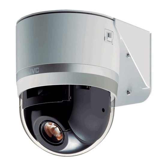
- Page 1 PTZ DOME CAMERA INSTRUCTIONS TK-C686E Thank you for purchasing this product. Before beginning to operate this unit, please read the instruction manual carefully in order to make sure that the best possible performance is obtained. LST0621-001A...
- Page 2 SAFETY PRECAUTIONS...
-
Page 3: Getting Started
Getting Started Features Safety precautions Mounting to a firm place Realizing a High Picture Quality As the unit rotates at high speed, mount it on a firm place This product uses high resolution 410,000 pixels CCD and a with sufficient strength to support the vibration and weight new digital image processing IC to achieve a standard of the unit (approx. -
Page 4: Table Of Contents
Getting Started Table of Content Detailed setting Private Mask Setting ............42 Home Motion Detect (Alarm) Setting ......44 HOME M.DETECT (TRACKING) Setting .....46 Manual Pan Limit Setting ..........48 Camera Title Setting ............50 Getting Started Area Display Mode Setting (Title) ........51 Features .................3 Area Display Mode Setting (Direction) ......52 Safety precautions ............3 Remote Control Alarm Title Setting ......53... -
Page 5: Precautions
Contents of this manual ● Locations prone to moisture such as window side. ● JVC holds the copyright to this manual. Any part or all of ● Locations subject to steam or oil, such as kitchens. this manual may not be reproduced without prior ●... -
Page 6: Getting Started
The camera will be damaged. If the wrong cable is connected, the internal circuit may be damaged. Do not use the camera. Bring it to your nearest JVC dealer for inspection. To supply AC 24 V, use a AC 24 V supplying power unit... - Page 7 Consumable parts Transportation The following are consumable parts. They must be Do not throw away the original box of the unit. Keep it and replaced once they reach their lifetime. use it for transporting the unit in future. The lifetime is only an estimation and differs according to As the camera unit is of an easily rotatable structure, the usage environment and conditions.
-
Page 8: Name And Function Of Parts
Getting Started Name and Function of Parts Ceiling clamping bracket Terminal Setting switch [ALARM I/O 2] Alarm Input 2 to 6/Alarm Output [CONTROL] Control signal connection terminal 2 Terminal (CN605) (J601) This is a terminal for alarm input 2 to 6 and alarm output 2. This connects the camera to the remote control unit (RM-P2580). - Page 9 Camera Fixing holes (x3) Camera fixing lock knob (x2) This hole is for mounting the ceiling clamping bracket to the This knob secures the camera to the ceiling so that it does ceiling or the ceiling recessed bracket (WB-S685U: Sold not fall.
-
Page 10: Connection/Installation
Connection/Installation System Connection Example Observe the following points when connecting components together: ● Turn all the components off before proceeding. ● Read the instruction manuals of all components before proceeding. ● For the types and lengths of connection cables, see [Cable Connection] (A Page 20) ●... -
Page 12: Camera Installation Procedures
Connection/Installation Camera Installation Mounting the Camera Procedures Install the camera with the following procedures. Preparation Preparation (A Page 12) Be sure to put on protective glasses to protect your eyes from falling objects when mounting on the ceiling. Make holes on the ceiling Mounting the ceiling clamping bracket (A Page 15) ●... - Page 13 The camera will be damaged. If the wrong cable is Caution connected, the internal circuit may be damaged. Do not use the camera. Bring it to your nearest JVC dealer for ● Take note of the length, strength, pull and material inspection.
- Page 14 Connection/Installation Mount the terminal cover Mounting the Camera Return the terminal cover that was removed in step to its (continued) original position. The direction to pull out the cables changes according to the mounting method of the camera. Pulling out the cables from the side Handling cables Terminal cover Thread the provided wire clamp through the wire clamp fixing...
-
Page 15: Mounting The Camera To The Ceiling
Mounting the ceiling clamping bracket to Mounting the camera to the ceiling the ceiling Remove the tape on the lens section Secure the ceiling clamping bracket on the ceiling Remove the lens cap Install such that the ADFRONT markB of the ceiling clamping bracket faces the front. - Page 16 Connection/Installation Note Mounting the Camera ● Before mounting the camera, check that the camera fixing (continued) lock knobs are not locked (i.e., lock knobs are on top). The camera cannot be mounted if the lock knobs are locked. ● When pulling out the cables from the side, remove the cable cover of the camera.
-
Page 17: Switch Setting
Switch Setting Setting Switch Before mounting the camera, set the switches on the ceiling clamping brackets. The setting differs according to the system used. Setting Switch Switch 1 Cable length switch Switch 2 Switch 3 Invalid Switch 4 system connection switch Switch 5 Switch 6 Invalid... - Page 18 Connection/Installation Machine ID Confirmation Procedures Switch Setting (continued) Output the image of the camera to be checked on the monitor Turn on the power of the camera ● The camera initializes and the following screen is displayed on the monitor. Machine ID Setting Switch When controlling the system via a multi DROP system such as RM-P2580, a machine ID will be attached to the system to...
- Page 19 Machine ID Set the machine ID using the combination of dip switch 1 to 8. (The factory default setting is OFF) Machine ID Machine ID setting switch Machine ID Machine ID setting switch Machine ID Machine ID setting switch Machine ID Machine ID setting switch 2 3 4 6 7 8 2 3 4...
-
Page 20: Cable Connection
Connection/Installation Alarm Input 2 to 6/Alarm Output 2 Terminal Cable Connection Provided alarm cable Provided alarm Coaxial cable cable Power cable Alarm signal cable Control signal cable Connecting the alarm input/alarm output terminals Cable color Signal Name Alarm input 1/Alarm output 1 terminal number Connecting alarm input 1/alarm output 1 terminal Brown... - Page 21 Alarm input terminal Connecting the coaxial cable Connects to sensors such as infrared sensors, door sensors, metal sensors and manual switches. Connecting a RG-59 coaxial cable. ● To prevent noise from entering the internal circuit, supply Treat the extremity of the coaxial cable as shown below non-voltage contact signal to the alarm input terminal.
- Page 22 Connection/Installation Overall view of control signal cable connection Cable Connection RM-P2580 (continued) Camera terminal 1 TO CAMERA Terminal Camera terminal 2 Connecting the control signal cable The maximum connection distance with RM-P2580 is 1200 m. (Multiple cameras can be connected on one cable for RM- P2580 but the total length of the cable must be within 1200 m.) Camera terminal 3 ●...
-
Page 23: Connecting The Power Cable
● If the wrong cable is connected, the internal circuit may be damaged. Do not use the camera. Bring it to your nearest JVC dealer for inspection. ● Turn on the power only after the connection for all the devices is complete. -
Page 24: Changing Camera Settings From Remote Control
Changing camera settings from remote control Turn AONB the power switch at the rear Setting Procedures The [POWER] lamp lights up. Press the [MENU] button for 3 seconds. ● The [MENU] button lamp lights up. ● The [SETUP] screen at the remote control is displayed You can call out the camera menu and set functions from the from [MONITOR OUTPUT-1]. - Page 25 Shift the [PAN/TILT] lever up and down to select items Press the [SET] button ● Press the lever to the left ( ) to minimize the numbers. ● Press the lever to the right ( ) to maximize the numbers. Change mark CAMERA FUNCTION1 V.
-
Page 26: Flow Of Menu Screens
Changing camera settings from remote control Flow of Menu Screens RM-P2580 The menu screen consists of the following flow. (For details, see the reference page for each item) (A Page 28) Normal screen CAMERA FUNCTION1 V.PHASE POS. TITLE LOC. UP-L Press [MENU] PRIVATE MASK.. - Page 27 (A Page 42) PRIVATE MASK MASK MODE MASK EDIT No 1 MODE MASK No.1 BRIGHT MASK No.2 MASK No.3 MASK No.4 MASK No.5 MASK No.6 MASK No.7 MASK No.8 < > < > < > MENU RETURN MENU RETURN EXECUTE <MENU>RETURN (A Page 44) MOTIOIN DETECT AREA EDIT...
-
Page 28: Camera Function1 Screen
Changing camera settings from remote control CAMERA FUNCTION1 screen (● indicates the default value) Item Setting value Functions and settings V.PHASE –156 to 0 to 156 This adjusts the vertical synchronization to those of other cameras when a selector switch for the synchronizing system on the Ceilling Mount is at LL. (50 Hz power (●... - Page 29 Item Setting value Functions and settings HOME M.DETECT (continued) HOME M.DETECT (ALARM) (continued) AREA EDIT.. This item sets the non-detection area. (A Page 44) ● 5s TIME This item sets the duration to output alarm signals. 6s, 7s, 8s, 9s, Note 10s, 15s, 20s, ●...
-
Page 30: Camera Function2 Screen
Changing camera settings from remote control CAMERA FUNCTION2 screen (● indicates the default value) Item Setting value Functions and settings When this item is set to AOFFB and the camera rotates vertically, the camera will FLIP stop when it faces down. AUTO ●... - Page 31 Item Setting value Functions and settings When the camera is not operated within the duration set in ATIMEB, it will AUTO RETURN automatically return to the state set in AMODEB. Note ● This function only works normally when the model name on the serial number plate of RM-P2580 is RM-P2580(A).
-
Page 32: Camera Title/Alarm Screen
Changing camera settings from remote control CAMERA TITLE/ALARM screen This screen allows you to configure title and alarm settings. (● indicates the default value) Item Setting value Functions and settings CAM.TITLE EDIT.. This item sets the title to be displayed permanently on the lower left of the screen. - Page 33 PRESET :Alarm signals are output when the camera is moved to the home position or to a preset position. AUX1,AUX2,AUX3 :Alarm signals are output when there is an auxiliary input. Memo ● In normal cases, do not use AAUX1B, AAUX2B, AAUX3B. For details, please consult your nearest JVC dealer.
-
Page 34: Camera Alc Screen
Changing camera settings from remote control CAMERA ALC screen This function performs automatic adjustment according to the brightness. It sets the video signals of the camera such as color level and contour enhancement. (● indicates the default value) Item Setting value Functions and settings ●... - Page 35 Item Setting value Functions and settings B&W/COLOUR This item sets the mode switching of B&W and Color. MODE.. Memo ● When switching the Color mode to B&W mode, the type of light source may cause the focus to be dislocated. This is because the B&W mode is sensitive to both visible light and near-infrared light.
-
Page 36: Camera Video Screen
Changing camera settings from remote control CAMERA VIDEO screen (● indicates the default value) Item Setting value Functions and settings ● CRT MONITOR TYPE This sets the monitor type. LCD1 You can change the output video settings according to the type of monitor used. LCD2 Select an appropriate mode. -
Page 37: Auto Pan/Patrol/Trace Screen
AUTO PAN/PATROL/TRACE screen This screen sets the Auto Pan function that rotates slowly in a horizontal direction, the Auto Patrol function that moves the camera to multiple positions in sequence, and the Auto Trace function that reproduces manual camera settings. (●... - Page 38 Changing camera settings from remote control AUTO PAN/PATROL/TRACE screen (continued) (● indicates the default value) Item Setting value Functions and settings AUTO PAN/TRACE This item sets the images during Auto Pan and Auto Trace. VIDEO IRIS MODE MANUAL This item sets the adjustment method for lens iris. ●...
- Page 39 Item Setting value Functions and settings AUTO PAN/TRACE VIDEO (continued) ● ATW-W W.BALANCE This item sets the white balance adjustment function. You can adjust the illumination within the color temperature range of 2,300K to 10,000K. ATW-N ATW-N :This is the Auto-Tracking White Balance mode. (Automatic color temperature tracking).
-
Page 40: Pos.function Set Screen
Changing camera settings from remote control POS.FUNCTION SET screen (● indicates the default value) Item Setting value Functions and settings POSITION TITLE.. This item sets a title of maximum 16 characters for the configured positions (99) and home position (1), and displays the title on the screen. (POS64 to POS99 cannot be selected. -
Page 41: Factory Settings Screen
Item Setting value Functions and settings ● ATW-W W.BALANCE This item sets the white balance adjustment function. You can adjust the illumination within the color temperature range of 2,300K to 10,000K. ATW-N ATW-N :This is the Auto-Tracking White Balance mode. (Automatic color temperature tracking). -
Page 42: Detailed Setting
Detailed setting Mask Setting Private Mask Setting Open the [MASK MODE] screen ● Shift the [PAN/TILT] lever to the left and right and set [MODE] to AONB. ● Press the [SET] button to display the [MASK MODE] This function allows you to configure settings to mask the screen. - Page 43 Level Setting Memo ● When [MODE] item is set to AOFFB, A- - -B will be Select [BRIGHT] at the [PRIVATE MASK] screen displayed and settings is disabled. ● Move the cursor ( ) to the [BRIGHT] item, shift the ●...
-
Page 44: Home Motion Detect (Alarm) Setting
Detailed setting Preparation Home Motion Detect Select a camera (A RM-P2580 Instruction Manual) [CAMERA] button B Numeric keypad (camera (Alarm) Setting number) B [ENTER] button ● Images from the selected camera are output. Display the [MENU] screen (A Page 24) When the camera is at the home position, the Motion Detect ●... - Page 45 Setting Note ● The Motion Detect feature is not designed to prevent Setting non-detection area thefts or fire disasters. Our company shall not be liable for ● Select [AREA EDIT..] and press the [SET] button. any inconveniences or damages that occur. ●...
-
Page 46: Home M.detect (Tracking) Setting
Detailed setting Preparation HOME M.DETECT Select a camera (A RM-P2580 Instruction Manual) [CAMERA] button B Numeric keypad (camera (TRACKING) Setting number) B [ENTER] button ● Images from the selected camera are output. Display the [MENU] screen (A Page 24) This item sets the function to automatically track objects with ●... - Page 47 Setting Note ● The Motion Detect feature is not designed to prevent Set [LEVEL] thefts or fire disasters. Our company shall not be liable for ● Move the cursor ( ) to the [LEVEL] item, shift the any inconveniences or damages that occur. [PAN/TILT] lever to the left and right and set the ●...
-
Page 48: Manual Pan Limit Setting
Detailed setting Preparation Manual Pan Limit Setting Select a camera (A RM-P2580 Instruction Manual) ● [CAMERA] button B Numeric keypad (camera number) B [ENTER] button ● Images from the selected camera are output. This feature sets the panning (horizontal) area during Display the [MENU] screen (A Page 24) manual operation. - Page 49 Setting Basic Operation of Manual Pan Limit ● When manual pan limit is set, panning is only available in Set the left limit position the effective area. ● Use the [PAN/TILT] lever (left/right) to determine the left ● This operation has priority over manual pan limit. When limit position.
-
Page 50: Camera Title Setting
Detailed setting Setting Camera Title Setting Check that the cursor ( ) is at [CAM.TITLE EDIT..] and press the [SET] button ● The [CAM.TITLE EDIT] screen is displayed. ● The first character from the character area flashes on A maximum of 16 characters can be set for the title. and off and is ready for input. -
Page 51: Area Display Mode Setting (Title)
Setting Area Display Mode Setting Move the cursor ( ) to [AREA DISPLAY], shift the (Title) [PAN/TILT] lever to the left and right to select ATITLEB, and press the [SET] button ● The [AREA TITLE EDET AREA1] screen is displayed. This function divides the 360 panning (horizontal rotation) area into (The home position corresponds to area No. -
Page 52: Area Display Mode Setting (Direction)
Detailed setting Area Display Mode Setting MENU (Direction) CAMERA FUNCTION1.. CAMERA FUNCTION2.. CAMERA TITLE/ALARM.. CAMERA ALC.. CAMERA VIDEO.. AUTO PAN/PATROL/TRACE.. When the basic axis direction N (north) is set, this function POS.FUNCTION SET.. FACTORY SETTINGS.. divides the 360 panning (horizontal rotation) area into 8 <... -
Page 53: Remote Control Alarm Title Setting
Setting Remote Control Alarm Title Move cursor ( ) to [ALARM TITLE EDIT..] and press Setting the [SET] button ● The [ALARM TITLE EDIT No.1] screen is displayed. ● The first character from the character area flashes on and off and is ready for input. This item sets the title to be displayed during alarm input. -
Page 54: Auto Pan Setting
Detailed setting Setting Auto Pan setting Select [AUTO PAN SET..] and press the [SET] button ● Check that the cursor is at [AUTO PAN SET..] and press the [SET] button ● The [AUTO PAN SET] screen is displayed. This item sets the auto pan function that rotates slowly in the horizontal direction. - Page 55 Press the [SET] button (only during ARETURNB) The start position switches to the end position. AUTO PAN POSITION SET AUTO PAN POSITION SET [END] POS.SET [END] POS.SET <SET>INVALID <SET>INVALID DURING PAN MOVEMENT DURING PAN MOVEMENT <MENU>RETURN <MENU>RETURN <SET>L/R <SET>L/R [AUTO PAN POSITION SET] screen (End position) Set the end position (only during Shuttle) ●...
-
Page 56: Auto Patrol Setting
Detailed setting Preparation Auto Patrol Setting Select a camera (A RM-P2580 Instruction Manual) ● [CAMERA] button B Numeric keypad (camera number) B [ENTER] button ● Images from the selected camera are output. This item sets the Auto Patrol function where the camera Display the [MENU] screen (A Page 24) moves to multiple positions in order. - Page 57 Setting To operate Auto Patrol: Shift up and down the [PAN/TILT] lever and move the ● To operate Auto Patrol in the camera, press the [AUTO cursor ( ) to a patrol number you wish to set PATROL] button of RM-P2580. ●...
-
Page 58: Auto Trace Setting
Detailed setting Preparation Auto Trace Setting Select a camera (A RM-P2580 Instruction Manual) ● [CAMERA] button B Numeric keypad (camera number) B [ENTER] button ● Images from the selected camera are output. This item sets the Auto Trace function (approx. 30 seconds) Display the [MENU] screen (A Page 24) that reproduces manual camera settings. - Page 59 Setting To operate Auto Trace: Set start position ● To perform Auto Trace on the camera, [RM.A.PAN KEY] ● Use the [PAN/TILT] lever and [FOCUS (NEAR) (FAR)], (A Page 39) item of the [AUTO PAN/PATROL/TRACE] screen must be set to AA.PANB. [ZOOM WIDE TELE)] buttons to set the start ●...
-
Page 60: Position Title Setting
Detailed setting Preparation Position Title Setting Select a camera (A RM-P2580 Instruction Manual) ● [CAMERA] button B Numeric keypad (camera number) B [ENTER] button ● Images from the selected camera are output. This item sets the title to be displayed when selecting Display the [MENU] screen (A Page 24) positions. - Page 61 Setting Check that the cursor ( ) is at the [POSITION TITLE..] item and press the [SET] button ● The Edit Position Title screen appears. ● The first character from the character area flashes on and off and is ready for input. Select a position (A RM-P2580 Instruction Manual) [POSITION] button B Numeric keypad (position number) B [ENTER] button...
-
Page 62: Auto White Balance Setting
Detailed setting Preparation Auto White Balance Setting Select a camera (A RM-P2580 Instruction Manual) ● [CAMERA] button B Numeric keypad (camera number) B [ENTER] button ● Images from the selected camera are output. Each light source has its own color temperature. Therefore, Display the [MENU] screen (A Page 24) when the main light source lighting an object is changed, set the [W.BALANCE] item to AAWCB and adjust the white... - Page 63 Setting Place a white object at the center of the screen, under the same lighting condition as the object to be shot and zoom in to fill the screen with white. Set [W.BALANCE] to AAWCB ● Shift up and down the [PAN/TILT] lever and move the cursor ( ) to the [W.BALANCE] item.
-
Page 64: Others
Others Troubleshooting Symptom Cause Action ● Are the power cables and coaxial cables connected ● Connect the cables correctly. Power does not turn on. correctly? ● Are the camera and ceiling clamping brackets ● Mount the camera and ceiling mounted securely? clamping brackets securely. -
Page 65: Specifications
Rotation platform Specifications Horizontal rotation range : 360 endless rotation Horizontal rotation speed : Approximately 0.04 /s to approximately 500 /s CAMERA HEAD Vertical rotation range Image pickup device : 1/4 type, Interline Transfer CCD 752 (H) – 5 to 185 (Horizontal - lower - Vertical) x 582 (V) Vertical rotation speed Synchronization system... - Page 66 Others Ceiling mounting hole [Unit: mm (inch)] Specifications (continued) FRONT mark Front of camera R160 (6 1/4) R140 (5 1/2) Camera outer Dimension [Unit: mm (inch)] diameter Screw mounting hole R160 (6 1/4) Screw mounting 23 (7/8) hole Position where cables are to be pulled out from the side 22.5 (7/8)
- Page 68 LST0621-001A © 2007 Victor Company of Japan, Limited...
Need help?
Do you have a question about the TK-C686E and is the answer not in the manual?
Questions and answers