
Related Manuals for JVC TK-C400E


Summary of Contents for JVC TK-C400E
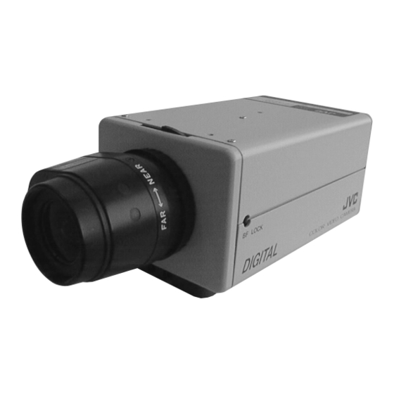
- Page 1 SERVICE MANUAL COLOR VIDEO CAMERA TK-C400U/TK-C400E/TK-C401EG (Lens is optional) TK-C400U/E TK-C401EG No. 6675 November 1997 COPYRIGHT © 1997 VICTOR COMPANY OF JAPAN, LTD.
-
Page 2: Table Of Contents
TERMINAL BOARD SCHEMATIC DIAGRAM .... 3-7 TERMINAL CIRCUIT BOARD ........3-7 3.10 PS BOARD SCHEMATIC DIAGRAM (TK-C400U/TK-C400E) ..........3-8 3.11 PS CIRCUIT BOARD (TK-C400U/TK-C400E) ....3-8 3.12 POWER BOARD SCHEMATIC DIAGRAM (TK-C401G) ..............3-8 3.13 POWER CIRCUIT BOARD (TK-C401G) ...... 3-8... -
Page 3: Important Safety Precautions
Important Safety Precautions Prior to shipment from the factory, JVC products are strictly inspected to conform with the recognized product safety and electrical codes of the countries in which they are to be sold. However, in order to maintain such compliance, it is equally important to implement the following precautions when a set is being serviced. - Page 4 Safety Check after Servicing Examine the area surrounding the repaired location for damage or deterioration. Observe that screws, parts and wires have been returned to original positions, Afterwards, perform the following tests and confirm the specified values in order to verify compli- ance with safety standards.
-
Page 5: Service Cautions And Disassembly
When replacing a fuse, make sure to use new one of the speci- fied part number for safety and protection of the set. Symbol TK-C400 TK-C401 Rating Parts No. Note Fig. 1-4 1A-125V QMF51U1-1R0 TK-C400U T1A-250V QMF51E2-1R0 TK-C400E T2A-250V QMF51E2-2R0 TK-C401EG... - Page 6 2) Remove two screws 3. 5) Disconnect a connector F, then remove the EE board. PRO board Fig. 1-7 6) Remove a screw 5, then remove the TERMINAL board with rear panel G. Fig. 1-5 Removal of PRO board In case of TK-C401, remove a screw 6 and connector H before removing the TERMINAL board.
-
Page 7: Replacement Of Color Ccd Image Sensor
REPLACEMENT OF COLOR CCD IMAGE SENSOR 7) Remove a screw 7, then slide the PS/POWER board in the direction of arrow to remove it. The CCD image sensor is not interchangeable with any- thing other than the specified one. Be careful in handling a new image sensor neither to leave fingerprints on the glass surface nor to make it stained with grease. -
Page 8: Installing Of Ccd Image Sensor
3) Remove two screws 9, then remove the front frame M. 1.4.2 Installing of CCD image sensor Note: Before installation, take notes of the code of the CCD image sensor. It needs to refer to this code for adjust- ment. 1st. -
Page 9: Electrical Adjustments
EVR with a computer. • CCD board IC 200 CCD Image sensor ICX 054AK-A: for TK-C400U ICX 055AK-A: for TK-C400E/TK-C401EG • PRO board IC205 EEPROM AK6420AM 2.1 REQUIRED MEASURING INSTRUMENTS FOR ADJUSTMENTS... -
Page 10: Required System For Adjustments
2.1.3 Required system for adjustments Equipments Specifications Computer 486DX4/100MHz or higher micro processor (Recommended Pentium Processor) Operating system Windows 95 or Windows NT 3.51 Memory 16M Byte or more 3.5 inch (1.44 MB) floppy diskette drive I/O port Serial port Hard disk unit 1 MB hard disk space 2.1.4 Required instruments for adjustment... -
Page 11: Standard Setup
2.2 STANDARD SETUP Supply power AC 24V/DC 12V TK-C400 REAR PANEL DC output Supply power AC230V Interface terminal TK-C401EG REAR PANEL PLSC1215 Computer 75 ohm 75 ohm Windows 95 or NT terminator terminator Oscilloscope Vetorscope Waveform Color monitor monitor (WFM) 2.3 SWITCH SETTING FOR ADJUSTMENT S500 VR500... -
Page 12: Notes
2.4 NOTES 2.4.1 Installation 2.4.3 What is “Initial Data” To install the adjustment program, perform the following proce- The initial data loaded at “2.5 INITIALIZE” consists of preset dure. adjustment values. Therefore, once the adjustment procedure 1) If you have any programs currently installed in the serial I/O is started, all adjustment should be done from beginning to the port, remove them. -
Page 13: Initialize
Adjustment level (+) Input signals 2.5 INITIALIZE 1) Select either “TK-C400U.cor” for TK-C400U or “TK-C400E.cor” for TK-C400E/401EG to on Scenario file define adjustment. 2) Selecting either “NEXT” or “BACK” button to be initialized the camera data. All EVR are installed the initial data. (See 2.4.3) 2.6 ADJUSTMENT OF SSG... -
Page 14: Adjustment Of Ccd
Measuring point (*) Measuring Adjustment parts (-) Item instrument & Mode Adjustment procedure Adjustment level (+) Input signals 2.7 ADJUSTMENT OF CCD * TP205 [PRO] VSUB voltage Digital voltmeter 1) Select the “NEXT” button to display “V - VSUB [CAT: DCREF, adjustment voltage”... -
Page 15: Adjustment Of Video Signal
Measuring point (*) Measuring Adjustment parts (-) instrument & Item Mode Adjustment procedure Adjustment level (+) Input signals 2.8 ADJUSTMENT OF VIDEO SIGNAL * VIDEO OUT (75 ohm White clip Oscilloscope 1) Select the “NEXT” button to display “White adjustment (H-rate: 10:1) or Termination) clip”... - Page 16 Measuring point (*) Measuring Adjustment parts (-) Item instrument & Mode Adjustment procedure Adjustment level (+) Input signals * VIDEO OUT Setup level Oscilloscope 1) Select the “NEXT” button to display “Setup adjustment (H-rate: 10:1) or (75 ohm Termination) level” on the title bar. - SETUP W.F.M.
-
Page 17: Adjustment Of White Balance
Measuring point (*) Measuring Adjustment parts (-) Item instrument & Mode Adjustment procedure Adjustment level (+) Input signals 2.9 ADJUSTMENT OF WHITE BALANCE * VIDEO OUT White Gray scale chart 1) Select the “NEXT” button to display “White balance (75 ohm Termination) balance (1)”... - Page 18 Measuring point (*) Measuring Adjustment parts (-) Item instrument & Mode Adjustment procedure Adjustment level (+) Input signals * VIDEO OUT White Gray scale chart 1) Select the “NEXT” button to display “White balance (75 ohm Termination) balance (3)” on the title bar. - LENS IRIS adjustment(3) filter...
- Page 19 Measuring point (*) Measuring Adjustment parts (-) instrument & Item Mode Adjustment procedure Adjustment level (+) Input signals * VIDEO OUT White White balance 1) Select the “NEXT” button to display “White balance chart (75 ohm Termination) balance (5)” on the title bar. - LENS IRIS adjustment (5) 2) Adjust the lens iris to obtain the specified level...
-
Page 20: Adjustment Of Chroma Signal
Measuring point (*) Measuring Adjustment parts (-) instrument & Item Mode Adjustment procedure Adjustment level (+) Input signals 2.10 ADJUSTMENT OF CHROMA SIGNAL * VIDEO OUT Color level Oscilloscope 1) Select the “NEXT” button to display “Color and hue (H-rote, 10:1) or (75 ohm Termination) level and Hue”... - Page 21 VICTOR COMPANY OF JAPAN, LIMITED Printed in Japan (S) T. A...
-
Page 22: Charts And Diagrams
SECTION 3 CHARTS AND DIAGRAMS SCHEMATIC DIAGRAM NOTES REPLACING SUBMINIATURE “CHIP” PARTS • Schematic safety precaution • Some resistors, shorting jumpers (0 ohm resistance), ceramic ! Parts are safety related parts. capacitors, transistors, and diodes are chip parts. These chip When replacing them, be sure to use the specified parts. -
Page 23: Block Diagram
BLOCK DIAGRAM PRO BOARD ON/OFF IC202 BLC SW CN200 Drive pulse P. BLK SYNC CN200 IC217 Buffer Vss1 Buffer VIDEO IRIS XSHP Vss2 Vsub XSHP IC200 Vss3 XSHO XSHD IC217 driver DC IRIS ADCK ADCK Vsub OSCO RG driver Q201 OSCI Q215/Q216 IC215... -
Page 24: Ccd Board Schematic Diagram
CCD BOARD SCHEMATIC DIAGRAM CCD CIRCUIT BOARD . SIDE A . 15.0 (CN201) . SIDE B . 12.5 -7.9 TP200 200mV/DIV , 10U/DIV Note : The parts in ( ) are not mounted on the board. -
Page 25: Pro Board Schematic Diagram
PRO BOARD SCHEMATIC DIAGRAM -7.9 10.2 -8.6 EEPROM 19.2 15.1 TG/V-DRV TO CCD SYNC DRIVER TIMING GENERATOR -7.9 PHASE COMP MODE 15.2 -7.9 DRIVER SYNC LATCH 22.3 14.0 DRIVER CHARGE 21.0 PUMP CLMP DRIVER DRIVER 12.6 CLMP TO EE GAIN R295 OPEN... -
Page 26: Pro Circuit Board
PRO CIRCUIT BOARD . SIDE A . . SIDE B . D212 D212 ADDRESS TABEL OF PRO BOARD PARTS Each address may have an address error by one interval. A-1C IC200 B-2A Q205 A-3B D208 B-6C R225 B-2E R282 B-6B R307 B-5E R332... -
Page 27: Ee Board Schematic Diagram
EE BOARD SCHEMATIC DIAGRAM VIDEO/DC D500-D503 : MA3240(M)-W R507 LEVEL GND(PRIMARY) GND(PRIMARY) C509 0.01 (R522) TO POWER (TK-C401EG) TO PS (TK-C400U/E) C520 1/25 C521 22/10 C515 C500 0.047 0.01 MA152WK MA152WK C522 22/10 Note : The parts in ( ) are not mounted on the board. -
Page 28: Ee Circuit Board
CN502 A-2A Q500 B-1A R521 B-2A Q501 A-3A R522 B-3A S500 A-2B TK-C400U and Q502 A-3A R530 B-1B TK-C400E only Q503 B-2A R531 B-1B TB500 A-3B R533 B-1A D500 B-3B R534 B-1A D501 B-2B D502 B-3B... -
Page 29: Ps Board Schematic Diagram (Tk-C400U/Tk-C400E)
PS BOARD SCHEMATIC DIAGRAM ( TK-C400U/TK-C400E ) PS CIRCUIT BOARD ( TK-C400U/TK-C400E ) 3.10 3.11 ADDRESS TABEL OF PS BOARD PARTS Each address may have an address error by one interval. 11.6 Y axis X axis GND(PRIMARY) -0.2 GND(PRIMARY) 12.4... -
Page 30: Block Diagram Of Ic's
3.14 BLOCK DIAGRAMS of IC'S AK6420AM-W [ASAHIKASEI] AN8085M-X [MATSUSHITA] MA1040P(4100) [SHINDENGEN] (2048 bits (128 Words X 16 bits) EEPROM) (REG Servo) (Power Modul) MB88347PFV [FUJITSU] (D/A Convertor) CXA2006Q [SONY] BA10358F-E2 [ROHM] (CDS and AGC) (Dual Ground Sense Op.Amp.) - Page 31 CXD2163AR [SONY] (Digital signal processor for single chip CCD color video camera) 3-10 3-10...
- Page 32 3-11 3-11...
- Page 33 CXD2312R [SONY] CXD2480R [SONY] (9 bit 20 MSPS Video A/D Converter) (Timing Control with CCD Drivers) 3-12 3-12...
- Page 34 3-13 3-13...
- Page 35 3-14 3-14...
- Page 36 ICX054AK-A [SONY] (1/3 inch CCD image sensor for NTSC color camera) 3-15 3-15...
- Page 37 ICX055AK-A [SONY] (1/3 inch CCD image sensor for PAL color camera) 3-16 3-16...
- Page 38 NJM2267V-W [JRC] NJM431U-X [JRC] NJM78L15UA-X [JRC] (Dual 6dB Video Amplifier including 75OHM Driver) (Adjustable Precision Shunt Regulator) (3-Terminal Positive Voltage Regulator (+15V)) NJM431U-XE [JRC] (Refer to NJM431U-X.) NJM79L08UA-X [JRC] (3-Terminal Negative Voltage Regulator (-8V)) NJM2509V-W [JRC] (Super Imposer including Y/C MIX Circuit) 3-17 3-17...
- Page 39 TC4053BF-X [TOSHIBA] TC7S08F-X [TOSHIBA] UPC358G2-W [NEC] UPC358G2-X [NEC] (Triple 2 Channel Analog Multiplexers/Demultiplexers) (2 Input Single AND Gate) (Dual Op.Amp.) (Refer to UPC358G2-W.) TC4W53F-X [TOSHIBA] TC74HC08AF-X [TOSHIBA] (2-Channel Multiplexer) (Quad 2-Input AND Gates) TK11333BMC-X [TOKO] (Regulator) PST9120N-X [MITSUMI] (System Reset(+2V)) TC7W02F-X [TOSHIBA] (2 Input Dual NOR Gate) 4-10...
- Page 40 TK11650U-X [TOKO] UPD5556G-W [NEC] (3-Terminal Positive Voltage Regulator) (CMOS Dual Timer) 5-11 3-19 5-11 3-19...
-
Page 41: Exploded View And Assembly Parts List
4.1 ASSEMBLY M 1 SAFETY PRECATION Parts identified by the ! symbol are critical for safety. Replace only with specified parts numbers. NOTE Parts not denoted by parts numbers are not supplied by JVC. for U-Ver. PRO BOARD EE BOARD for EG-Ver. - Page 42 9 SCV2511-001 OP L.P.F. for TK-C400U/TK-C400E/TK-C401EG 10 SC45592H-001 SENSOR MASK 11 ICX054AK-A SONY for TK-C400U 11 ICX055AK-A SONY for TK-C400E/TK-C401EG 12 SC31797H-001 SENSOR HOLDER 13 SCV2337-1605BD FFC CABLE (1) CCD to PRO 14 SCV1902H-1805K FFC CABLE (2) TERMINAL to EE...
-
Page 43: Packing
SECTION 6 PACKING Instructions SC96795H (TK-C400U/E) (English, French, Spanish) Instructions SC96796H (TK-C400E only) (Germany, Italian, Chinese) 4P Plug SCV2859-001 Carton Instructions SC96795H (English, French, Spanish) Instructions SC96796H (Germany, Italian, Chinese) Power Cord Carton Carton Carton Box TK-C401EG only... - Page 44 Parts identified by the ! symbol are criticaI for safety. Replace only with specified parts numbers. For maximum reliability and performance, all other replacement parts should be identical to those specified. NOTE: ● Parts not denoted by parts numbers are not supplied by JVC. ● Abbreviations in this list are as follows: RESISTORS CAPACITORS In the “Description”...
- Page 45 5.1 CCD BOARD ASSEMBLY PARTS LIST SCK2467-01-N0A (TK-C400U) 01`````` SCK2467-01-P0A (TK-C400E/401EG) Symbol Symbol Part No. Part Name Description Part No. Part Name Description SK200 SCV2154-001 IC SOCKET 16PIN Q214 MSB1218A/R/-X TRANSISTOR MOTOROLA Q215 XP6401-W TRANSISTOR MATSUSHITA Q216 XP6534-W TRANSISTOR MATSUSHITA...
- Page 46 [PRO BOARD] Symbol Symbol Part No. Part Name Description Part No. Part Name Description R292 NRSA63J-472X M.G.RESISTOR 4.7k 1/16W R386 NRSA63J-332X M.G.RESISTOR 3.3k 1/16W R293 NRSA63J-0R0X M.G.RESISTOR 1/16W R387 NRSA63J-100X M.G.RESISTOR 1/16W R296 NRSA63J-333X M.G.RESISTOR 1/16W R388 NRSA63J-100X M.G.RESISTOR 1/16W R297 NRSA63J-333X M.G.RESISTOR...
- Page 47 Symbol Symbol Part No. Part Name Description Part No. Part Name Description C275 NCF31CZ-104X CER.CAPACITOR L203 NQL054J-5R6X COIL 5.6uH C276 NEH90JM-336X E.CAPACITOR 6.3V L205 NRS181J-0R0X SW.TRANSFORMER 1/8W C282 NCF31CZ-104X CER.CAPACITOR L211 NQL02BJ-150X COIL 15uH C283 NDC31HJ-101X CER.CAPACITOR 100p NQL02BJ-8R2X COIL 8.2uH C284 NCF31CZ-104X...
- Page 48 5.4 TERMINAL BOARD ASSEMBLY PARTS LIST 5.3 EE BOARD ASSEMBLY PARTS LIST SCK2468-02-N0A (TK-C400U) SCK2467-03-N0A (TK-C400U) SCK2468-02-P0A (TK-C400E) 03`````` 04`````` SCK2467-03-P0A (TK-C400E/401EG) SCK2468-02-E0A (TK-C401EG) Symbol Symbol Part No. Part Name Description Part No. Part Name Description IC501 BA10358F-E2 I.C.(M) ROHM...
- Page 49 5.5 PS BOARD ASSEMBLY PARTS LIST SCK2468-01-N0A (TK-C400U) 05`````` SCK2468-01-P0A (TK-C400E) Symbol Symbol Part No. Part Name Description Part No. Part Name Description NJM431U-XE I.C.(M) SCV2446-012 CONNECTOR 12PIN 2SK2490 SHINDENGEN SSV2497-001Z FUSE HOLDER 2SC3311A/RS/-T TRANSISTOR MATSUSHITA SSV2497-001Z FUSE HOLDER 2SC3311A/RS/-T...
- Page 50 5.6 POWER BOARD ASSEMBLY PARTS LIST 06`````` SCK2476-01-E0A (TK-C401EG) Symbol Symbol Part No. Part Name Description Part No. Part Name Description IC700 MA1040P(4100) I.C.(M) MAXIM IC701 NJM431U-X I.C.(M) D700 S1WB/A/60 DIODE SINDENGEN D701 MA152WK-X DIODE MATSUSHITA D702 RD4.7FM-X ZENER DIODE D703 ERA15-06-T1 DIODE...
- Page 51 COLOR VIDEO CAMERA...
Need help?
Do you have a question about the TK-C400E and is the answer not in the manual?
Questions and answers