Table of Contents
Advertisement
Advertisement
Table of Contents

Subscribe to Our Youtube Channel
Related Manuals for JVC TK-C655


Summary of Contents for JVC TK-C655
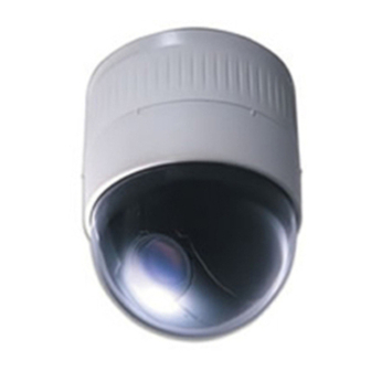
- Page 1 DOME TYPE CAMERA TK-C655 INSTRUCTIONS LWT0050...
-
Page 2: Important Safeguards
IMPORTANT SAFEGUARDS 1. Read all of these instructions. 2. Save these instructions for later use. 3. All warnings on the product and in the operating instructions should be adhered to. 4. Unplug this appliance system from the wall outlet before cleaning. Do not use liquid cleaners or aerosol cleaners. Use a damp cloth for cleaning. -
Page 3: Table Of Contents
WARNING: TO REDUCE THE RISK OF FIRE OR ELECTRIC SHOCK, DO NOT EXPOSE THIS APPLIANCE TO RAIN OR MOISTURE. Thank you for purchasing this product. (These instructions are for TK-C655E) Before beginning to operate this unit, please read the instruction manual carefully in order to make sure that the best possible performance is obtained. -
Page 4: Introduction Features
CAUTION • Installation of this unit requires special skills. Please be sure to consult JVC authorized dealer about installation procedures. If the mounting screws or nuts are not tightened sufficiently, the camera may fall from its installation location. Be sure to tighten the mounting nuts firmly to prevent this happening. -
Page 5: Precautions For Correct Operation
Precautions for Correct Operation Note on consumable parts The following parts are consumable and should be replaced after a certain number of hours or a count of operations. The service lives given below are only typical values. They may vary depending on the operating environment and conditions. -
Page 6: Controls, Connectors And Indicators
Introduction Controls, Connectors and Indicators Ceiling Mount Cover (Connector side) [VIDEO OUT] Coaxial Cable Connectors Output connector of a composite video signal (1 V(p-p)) with an output impedance of 75 Ω, to be connected to a switcher, etc. [AC ` 24V INPUT] Connector Connect to a 24 V AC power supply. - Page 7 Ceiling Mount (Setting switch side) Camera Connector (Female) Connect to , the Male Connector on the camera. Drop Prevention Hook Attach the Drop Prevention Wire the camera from falling. Clamping Holes (x 4) Attach the camera to a ceiling or to a Flush Mounted Ceil- ing Bracket (optionally available) using these holes.
-
Page 8: Connections & Installation A Multi-Drop Communication System
A system that employs the RM-P2580 as the controller The following figure shows a system that can accommodate up to eight cameras. (64 positions can be preset per camera.) Control signal cable TK-C655 Coaxial cable Camera 1 MACHINE ID: 01... - Page 9 A system that does not employ the RM-P2580 as the controller MEMO Be sure to terminate the control signal cable at both ends. The cables (length of stub) connecting pieces of non-terminated equipment (cameras or controllers) must be as short as possible. If the length of stub is too long, the precision of the control may suffer.
-
Page 10: Point-To-Point Communication System
TV transmitter, a power transformer or an electric motor, the picture may suffer from noise and colours may be affected. In order to operate and control the TK-C655 camera, a separate control unit accessory is required. Please contact JVC author- ized dealer or installer for more information about these controllers. - Page 11 Use twisted-pair cables for the connections. ●Duplex When the camera is controlled using the full duplex trans- mission protocol, set Switch 5 to OFF. Camera RX– TX– Four wires must be connected. For example (connection with an RM-P2580) Camera RX+ C RX–...
-
Page 12: Switch Settings
Connections & Installation Switch Settings Set the switches on the Ceiling Mount prior to installing the camera. Settings will vary according to the configuration of the system. Setting switches ● Switches 1, 2 These switches must be set to OFF. ●... -
Page 13: Setting Switches
Setting switches ● Machine ID When using a multi-drop system with a remote control unit such as a RM-P2580, the machine IDs need to be set for each camera. Machine IDs are used to identify each of the multiple cam- eras connected to the RM-P2580. -
Page 14: Cable Connections
(Be sure to use a drip-proof pipe. The maximum diametre of the pipe connector is 31 mm.) When distributing the cable from the side, use JVC’s WB- S573 ceiling direct-mount bracket. In this case, the length of the connector should be 33 mm or less, and the maxi- mum diameter of the tube should be 22 mm or less. -
Page 15: Coaxial Cable
Coaxial cable Connecting a RG-59 coaxial cable. If a RG-11 coaxial cable is used it cannot be con- nected directly to the terminal board. To use such a cable, connect a RG-59 cable to the camera and then connect the RG-11 cable to the RG-59 cable. Trim the end of the coaxial cable as shown below before connecting it. -
Page 16: Attaching The Ceiling Mount
Connections & Installation Attaching the Ceiling Mount To a ceiling slab or channel Ceiling Mount Screws Attaching the Camera Attaching a safety wire. Attach a safety wire to the Ceiling Mount and to the ceil- ing slab or channel to prevent the unit from being able to fall to the floor. - Page 17 Ceiling Mount Camera Camera clamping bracket Rotate the camera clockwise. Lock screw Tighten the locking screw. Ensure that the locking screw is loose. Locking screw The camera cannot be attached properly if the locking screw of the Ceiling Mount is too tight at this stage. Fit the camera.
-
Page 18: Setting Up The Camera Using An Rm-P2580 Setup Procedure
Setting Up the Camera Using an RM-P2580 Setup Procedure In systems using an RM-P2580 remote control unit, the menus for use during camera setup can be displayed on the remote control unit. (Please refer to the instructions for RM-P2580.) <Setting the camera menus from an RM-P2580> Power switch MENU button (Rear panel) -
Page 19: Menu Screen Flow
Menu Screen Flow The menu screens are arranged in a hierarchical structure as shown below. Refer to the respective reference pages for the details of each menu. Normal screen S E T U P P O S I T I O N S E T U P . -
Page 20: Camera Function Screen
Setting Up the Camera Using an RM-P2580 CAMERA FUNCTION Screen This screen sets up the functions of the camera itself. Item V. PHASE This adjusts the vertical synchronization to those of other cameras when a selector switch for the synchronizing system on the Ceilling Mount is at LL. (50 Hz power region only.) Setting values : –156 to 0 to 156 POS. -
Page 21: Camera Title/Alarm Screen
CAMERA TITLE/ALARM Screen This screen sets items related to titles and alarms. *This unit is not equipped with alarm input/output. The item ALARM TITLE is used to set the alarm title, which is displayed when an alarm signal is input to the RM-P2580 remote control unit. -
Page 22: Camera Video Adjustment Screen
Setting Up the Camera Using an RM-P2580 CAMERA VIDEO ADJUSTMENT Screen This menu sets the picture signal of the camera, such as the colour level and contour enhancement. Item COLOUR LEVEL Sets the colour level of the picture signal. To increase To decrease Setting values : –5 to NORMAL to 5. - Page 23 CAMERA ALC/ExDR Screen (Continued) Item AGC MODE Sets the maximum gain of the AGC (Auto Gain Control), which electronically in- creases the gain when the object is under low light conditions. : Turns the AGC off. 10 dB : According to the brightness of the object, gain is increased by up to 10 dB 20 dB : According to the brightness of the object, gain is increased by up to 20 dB SUPER : Use this setting when brightness is still insufficient under the “20 dB”...
-
Page 24: Auto Pan/Patrol/Trace Screen
Setting Up the Camera Using an RM-P2580 AUTO PAN/PATROL/TRACE Screen This screen sets up the auto pan function for slow panning, the auto patrol function for switching of positions in sequence, and the auto trace function for the reproduction of the results of manual camera operations. Item AUTO PAN MODE Determines movement during auto panning. -
Page 25: Factory Settings Screen
POSITION FUNCTION SET Screen (Continued) Item Sets of area of back light compensation. Use this function when the object appears dark (under auto iris control) because of the presence of a bright light source be- hind it. This function make it possible to place the unnecessary light source outside the photometry area. -
Page 26: Private Mask Setup
Setting Up the Camera Using an RM-P2580 PRIVATE MASK Setup Use the PRIVATE MASK screen to set up the private mask function, which grays out areas that are not required to be included in the monitored picture. Up to four private masks can be set per screen, and up to eight private masks can be set in total. MENU button SET button REMOTE CONTROL UNIT... -
Page 27: Camera Title Setup
CAMERA TITLE Setup Use the CAMERA TITLE screen to set the title of each camera. Titles can be up to 16 characters in length and are displayed at the bottom left of the picture. MENU button SET button REMOTE CONTROL UNIT RM-P2580 CAMERA POSITION... -
Page 28: Area Title Setup
Setting Up the Camera Using an RM-P2580 AREA TITLE Setup The 360° panning range of the camera can be divided into 16 equally sized areas and an area title can be set for each area. Titles can be of up to 16 characters in length and are displayed in the picture as the camera is panned manually. (Area title display ON/OFF: P. -
Page 29: Alarm Title Setup
ALARM TITLE Setup This unit is not equipped with alarm input/output. This function sets up the alarm title to be displayed when an alarm signal is input to the RM-P2580 remote control unit. Up to 10 alarm titles (ALARM TITLE 1 to 10) can be set and each title can be up to 12 characters in length. MENU button SET button REMOTE CONTROL UNIT... -
Page 30: Auto Pan Setup
Setting Up the Camera Using an RM-P2580 AUTO PAN Setup Use the AUTO PAN screen to set the auto pan function, which allows the camera to be revolved slowly in a horizontal direction) The auto pan function has three modes, the RETURN mode for continual movement between two positions, the RIGHT mode for clockwise rotation and the LEFT mode for anti-clockwise rotation. -
Page 31: Auto Patrol Setup
AUTO PATROL Setup Use the AUTO PATROL screen to set the configuration of the auto patrol function, which moves the camera between several positions at a high speed. Patrol positions 1-100 can be set in each of three modes (MODES 1 to 3). It is recommended that these three modes be set the according to the day of the week or the time of day. -
Page 32: Auto Trace Setup
Setting Up the Camera Using an RM-P2580 AUTO TRACE Setup Use the AUTO TRACE screen to set the auto trace function, which stores and reproduces the actions of a manual camera opera- tion (for 30 seconds). MENU button SET button REMOTE CONTROL UNIT RM-P2580 CAMERA... -
Page 33: Position Title Setup
POSITION TITLE Setup Use the POSITION TITLE screen to set the title of each camera position. Each camera position can be given a title of up to 16 characters. MENU button SET button RM-P2580 REMOTE CONTROL UNIT CAMERA POSITION SETUP POWER ALARM MENU... -
Page 34: Other
Other Attaching a Flush Mounted Ceiling Bracket (Optional WB-S575) The Flush Mounted Ceiling Bracket (optional WB-S575) allows the camera to be installed flush with the ceiling surface. In this case the ceiling material should have a thickness of between 5 mm and 31 mm. Mounting hole Anchor bolt mount holes Clamping screw... - Page 35 Anchor bolt mount holes Flush Mounted Ceiling Bracket attached to the ceiling Ceiling Mount Screws (For attaching the Ceiling Mount to the Flush Mounted Ceiling Bracket) Hook MEMO Both the Flush Mounted Ceiling Bracket and the safety wire should be insulated from the ceiling structure. If the ceiling structure is made of a metallic material, inadequate insulation with the camera may produce noise in the video output.
-
Page 36: Removing A Flush Mounted Ceiling Bracket (Optional Wb-S575)
Other Removing a Flush Mounted Ceiling Bracket (Optional WB-S575) Stoppers Push the stopper release lever Release upwards with a screwdriver, etc. label <Check the release labels thoroughly before removal.> Remove the ceiling panel. Pull down the ceiling panel and disengage the two hooks either side. Remove the camera. -
Page 37: Troubleshooting
Troubleshooting Symptom Is there a problem in the power cable(s) connecting the No picture is displayed. camera to the power supply unit? (If the power cable(s) are too long or of an inadequate size, the correct voltage may not be supplied due to an increase in cable resistance.) Are cables connected properly to the terminal board on No power to the... -
Page 38: Specifications
Other Specifications ■ Camera Image pickup device : 1/4 inch type, interline transfer CCD, 752(H) x 582(V) pixels. Sync system : Line Lock, Internal Scanning frequencies : Horizontal 15.625 kHz, Vertical 50 Hz : 50 dB (typical), (AGC OFF, ENHANCE –5) Minimum object : 6 lx (50% output, AGC 20 dB, illumination... - Page 39 ■ External dimensions [Unit: mm] (40) ( φ 75) φ 152 ■ WB-S575 (Flush Mounted Ceiling Bracket + Ceiling panel) Ceiling panel ■ Ceiling Mount hole for WB-S575 Ceiling Mount hole (Plate thickness: 5 mm to 31 mm) ■ Ceiling Mount hole Screw positions ■...
- Page 40 is a registered Trademark owned by VICTOR COMPANY OF JAPAN, LTD. is a registered Trademark in JAPAN, the U.S.A., the U.K. and many other countries. © 2002 VICTOR COMPANY OF JAPAN, LIMITED VICTOR COMPANY OF JAPAN, LIMITED Printed in Thailand LWT0050...
Need help?
Do you have a question about the TK-C655 and is the answer not in the manual?
Questions and answers