
Related Manuals for Clear-Com Tempest 900


Summary of Contents for Clear-Com Tempest 900
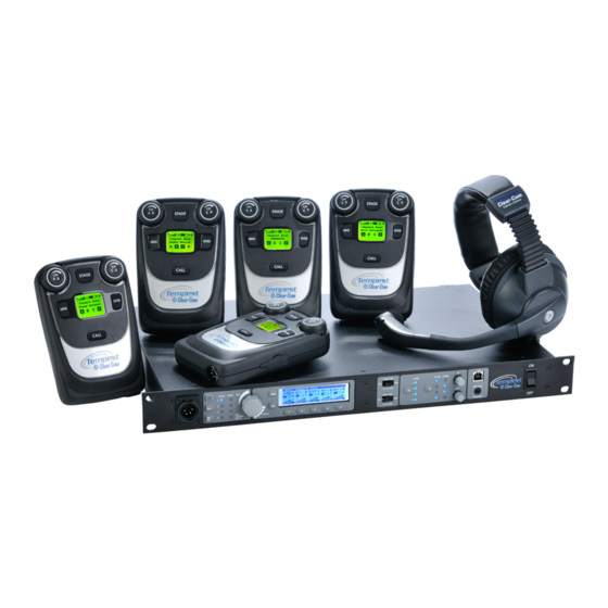
- Page 1 Tempest ® 4-Channel Wireless Intercom Reference Manual 399G079 Rev A 11-July-2014...
- Page 3 Thank you from Clear-Com We at Clear-Com want to thank you for purchasing a Tempest®900 Wireless Intercom System. We have made every effort to build a reliable, intuitive wireless intercom system that easily interfaces with your existing equipment and provides the same functionality that you expect from your hard-wired intercom equipment.
- Page 4 No part of this document may be reproduced in any form by any means without prior written authorization of Clear-Com, an HME Company. Clear-Com Offices are located in California, USA; Cambridge, UK; Montreal, Canada; and Beijing, China. Specific addresses and contact information can be found on Clear-Com’s corporate website: Website: www.clearcom.com...
-
Page 5: Table Of Contents
Table of Contents Important Safety Instructions ........................1 A/C Power Warning ..........................2 Battery Safety ............................3 Maintenance and Care ..........................4 Quick Start Guide ........................... 6 What You Will Need ..........................6 Theory of Operation ..........................8 Accessory Items You May Require ......................11 BaseStation Overview ..........................12 Front Panel Left ............................12 Front Panel Right ............................14... - Page 6 BeltStation .............................. 70 Tempest Remote Transceiver ........................71 Tempest Part Numbers .........................73 900 MHz System Specifications ......................75 BeltStation Specifications ........................77 Remote Transceiver Specifications ......................77 Glossary ...............................79 Technical Support ..........................86 Tempest Block Diagram ........................90 Index ..............................92...
-
Page 7: Important Safety Instructions
Important Safety Instructions The word “Caution” is the lowest of the three signal words (Caution, Warning and Danger), with “Danger” being the highest. Therefore, whenever the word “Caution” is used, it may be replaced with either of the higher rated signal words: “Warning”... -
Page 8: A/C Power Warning
A/C Power Warning Users should exercise extreme care when working with electricity. Additional care should be used when working with electricity outdoors in inclement weather. When working outdoors or near water, always connect the system into a ground-fault interrupting circuit. There are no user-serviceable parts inside the Tempest BaseStation, Transceiver, or BeltStation. -
Page 9: Battery Safety
Battery Safety Battery Transportation Rechargeable lithium batteries are subject to special regulation by U.S. and International laws, particularly regarding transportation on passenger aircraft. However, individual batteries installed in consumer electronics are not restricted, provided there are only the correct numbers and types of batteries as may be needed to operate the electronic equipment. -
Page 10: Maintenance And Care
Maintenance and Care Cleaning Generally, the Tempest Wireless hardware should be cleaned only with a dry cloth. A soft cloth with rubbing alcohol may be used to wipe the units if needed. Never spray solvents or chemicals onto the units. Because of Tempest’s weather resistant design, it is not highly susceptible to dust or airborne contaminants. - Page 11 [This page intentionally left blank] Tempest®900 4-Channel Wireless Intercom System...
-
Page 12: Quick Start Guide
Quick Start Guide What You Will Need BaseStation » Power cord » One BaseStation antenna » 3.5mm male-to-male mini-stereo pairing cable BeltStations » Up to 5 per BaseStation » Lithium-Polymer battery and » Charger - 1 per BeltStation Headsets (customer supplied) »... - Page 13 4. Pair BeltStations to the BaseStation Pairing is a programming process that allows a BaseStation and BeltStation to recognize each other. » Confirm that the BaseStation is powered ON. » Confirm that the BeltStation is powered OFF. » Connect the Pairing Cable from the BaseStation to a BeltStation. »...
-
Page 14: Theory Of Operation
Theory of Operation Tempest is a DSP (Digital Signal Processor) based, full duplex, wireless intercom system. It is a digital, point-to-point communications system, operating in 26 MHz of spectrum in the 900MHz frequency band. This band allows users to operate with no license requirements in most locations. The 900MHz band offers many benefits. - Page 15 because there is no system latency delay. Tempest uses advanced echo-cancellation algorithms to eliminate this echo. Wireless intercom systems are often used in high-noise environments that require special design consideration for effective operation. Tempest operates extremely well even in very high ambient noise levels. This is primarily due to specific design criteria which allow Tempest to achieve an audio dynamic range of greater than 94dB.
- Page 16 What’s In The Box BaseStation BaseStation AC Power Cord (1) Whip Antenna ½ Wave Pairing Cable USB-A to USB-B Cable USB-A to Mini-USB Cable Documentation CD Quick Start Guide BaseSync Cable BeltStation BeltStation Lithium-Polymer Rechargeable Battery Battery Charger/Power Supply Remote Transceiver Remote Transceiver CAT-5 Cable for BaseStation Connection - 15 Feet Whip Antenna ½...
-
Page 17: Accessory Items You May Require
If you plan to connect the Tempest BaseStation to external 2-Wire party-line intercom systems, you will need to provide the appropriate 3-PIN XLR cabling. RJ-45 Connector Cable for 4-Wire If you plan to connect the Tempest BaseStation to external Clear-Com 4-Wire intercom systems, you will need to provide the appropriate cabling. RJ-45 to RJ-12 Adapter If you plan to connect to an RTS 4W system, you will need adapters. -
Page 18: Basestation Overview
BaseStation Overview Front Panel Left 1- Local Headset Connector The 4-PIN XLR male headset connector is compatible with most Dynamic or Electret headsets that have 4-PIN XLR female connectors. This headset connector allows a user to communicate on any one of the four intercom channels. Controls for this connector are located to the immediate right. -
Page 19: Volume Control
7- Volume Control The multipurpose Volume control operates differently depending on the mode of the BaseStation. In Operational Mode, turning the Volume control adjusts the volume of the local headset. Turning the Volume control clockwise increases the audio level, while turning the control counter-clockwise decreases the level. Press the Volume control to select the intercom channel to be monitored at the local headset connector. -
Page 20: Front Panel Right
The two 2-Wire Intercom Type slide switches configure the BaseStation for the type of intercom that will be connected to the corresponding 2-Wire connectors on the rear panel of the BaseStation. Clear-Com, RTS, or BAL (AudioCom) can be selected. This switch only affects 2-Wire operation and not 4-Wire operation. The A&B switch selects the 2-Wire system type for both the A and the B intercom channels. -
Page 21: Beltstation Program Connector
4- 2-Wire/4-Wire Select (SEL) Button The 2-Wire/4-Wire Select (SEL) button sets the wired intercom mode for each of the four intercom channels. When a channel is selected with the CHAN SEL button, pressing the 2-Wire/4-Wire Select (SEL) button changes the selected intercom mode between 2-Wire, 4-Wire, or no connection. -
Page 22: Rear Panel Left
The Intercom Channel connectors (A/B/C/D) allow the user to connect the Tempest BaseStation to 2-Wire external intercom systems or other Tempest BaseStations. The XLR-3M/F 2-Wire intercom connectors interface with Clear-Com, RTS, Balanced and other compatible intercom systems. The pairs of XLR3-M and XLR-3F are electrically identical. -
Page 23: Rear Panel Right
Rear Panel Right 1- SA (Stage Announce) Connector The SA connector is used to output BeltStation audio to a dedicated audio output. The SA Connector is an XLR-3M connector and accepts a standard XLR-3F. The SA Connector is balanced and transformer isolated. Nominal line level is -12 to +8 dBu. The SA Connector output level can be adjusted under the Wired Intercom Settings menu. - Page 24 6- Local Area Network (LAN) RJ-45 Connector The Local Area Network (LAN) RJ-45 Connector is used to connect the Tempest BaseStation to a user supplied PC running Tempest Desktop Configuration (T-Desk®) software. The user can then monitor and/or adjust BaseStation and BeltStation settings via the PC interface.
-
Page 25: Beltstation Overview
BeltStation Overview 1- Volume- CH A/B and CH C/D In Operational Mode, turning the Volume control adjusts the volume of the audio. Volume indicators appear on the display during adjustment and are expressed in Decibels (dB). The Volume control has an option to be set to “Volume Press” where it requires a “press and turn”... -
Page 26: Beltstation Pairing Connector
6- CALL Button The CALL Button sends a 2-Wire compatible call signal to any wireless BeltStation and any hard wired intercom device on the intercom channel. The Call signal will be routed to intercom channels indicated by the user’s active Talk button(s). 1- Rubberized Access Cover The Rubberized Access Cover helps prevent dust, dirt and liquid from entering the BeltStation through the USB or the BeltStation pairing connector. - Page 27 Talk Button A/B and C/D There are two TALK buttons on each BeltStation, one for channels A/B and the other for channels C/D. The Talk button enables the microphone signal for the assigned intercom channels. Tempest uses an intelligent latching method for TALK buttons. Pressing the TALK button momentarily will cause the TALK button to latch.
-
Page 28: Transceiver Controls
Bottom view of the transceiver Transceiver Controls 1- RX LED The RX LED illuminates when data is being received by the Remote Transceiver. This LED will remain illuminated during normal system operation. 2- TX LED The TX LED illuminates when data is being sent from the Remote Transceiver. This LED will remain illuminated during normal system operation. -
Page 29: Basestation Setup
BaseStation Setup Steps to Setup the BaseStation • Choose a location for the BaseStation • Choose an antenna location and configuration • Maximize performance • Configure operation features • Set Network Number and Lockout Key » Name each BaseStation and BeltStation (optional, but encouraged) »... -
Page 30: Power Connections
Power Connections The Tempest BaseStation can be powered by AC or DC power, and uses an auto-switching power supply; therefore, if both AC and DC are connected, the BaseStation will automatically switch to DC in the event AC power is interrupted.. The front panel ON/OFF switch controls AC and DC power coming into the BaseStation. -
Page 31: Antenna Location
Antenna Location 24” Proper antenna location is essential for optimum system performance and maximum range. Antenna positioning is important with all RF systems and in all applications. Locate the Tempest BaseStation antenna as high as possible for your application to maximize line-of-sight RF operation. Positioning the antenna higher than head level is the minimum acceptable height for most applications. -
Page 32: Antenna Configurations
Antenna Configurations Option 1 Install the BaseStation in the center of the area of communication, with antenna installed on the back of the BaseStation, having a clear line of sight in all directions. When attaching the supplied ½ Wave Omnidirectional Whip antenna directly to the back of the BaseStation, always ensure that the antenna is firmly seated, is not cross threaded, and is located away from any metal obstructions. -
Page 33: Remote Transceiver
Remote Transceiver Setup the Transceiver • Choose a BaseStation location. • Choose a Transceiver location. • Choose an antenna configuration. • Install CAT-5 cable and connect to the BaseStation and Transceiver. • Confirm operation by observing the Transceiver LEDs. The Tempest Remote Transceiver is an optional accessory that allows antennas to be located up to 1,500 feet away from the BaseStation without the RF signal loss that is associated with using long runs of coaxial cable. -
Page 34: Maximizing System Performance And Operational Range
Maximizing System Performance and Operational Range Radio waves can be significantly affected by walls, windows, or other physical barriers. Concrete or metal walls can be of particular concern. Some tinted windows are also significant barriers to RF. Always position antennas to minimize interference from all barriers. -
Page 35: Configure The Basestation
Configure the BaseStation BaseStation settings can be configured in two ways: from the BaseStation menu or with the computer interface called “T-Desk” via a LAN connection. While many functions are available through both methods, certain features may only be available through the BaseStation. Using the Front Panel Controls The Tempest BaseStation can be configured depending on user preferences and the tasks to be accomplished. -
Page 36: Adjust Sidetone
Adjust Sidetone To demonstrate the use of the controls, this details instructions to adjust the “Sidetone” for the front panel headset connector: 1. Press MENU to enter Menu Mode 2. Rotate the Volume knob and scroll to “BaseStation Settings” on the display 3. -
Page 37: Network Number And Lockout Key
Synchronized BaseStations must utilize the same Network Number Group for optimal performance to be achieved. Under ideal conditions, three to five Tempest 900 BaseStations can be utilized in one Network Number Group. For example, a configuration using three Tempest 900 BaseStations would assign each BaseStation a Network Number (0,1,2) from Group One. - Page 38 Adjusting Network Number and Lockout Key The Network Number and Lockout Key settings can be adjusted from the BaseStation, under the “Radio Configuration” section of the Tech Menu. Any adjustment to the Network Number and/or Lockout Key will require corresponding BeltStations to be re-paired with updated BaseStation.
-
Page 39: Set Display Mode To Static Or Dynamic
Set Display Mode to Static or Dynamic The Static or Dynamic selection only affects the order that the BaseStation LCD Operational screen displays BeltStation information. “Static” will be the preferred choice for users who want to ensure that a BeltStation that is logged in will always appear in the same location (slot) on the BaseStation display and are using only one BaseStation. -
Page 40: Basestation Headset Connection And Controls
BaseStation Headset Connection and Controls The BaseStation headset connection is a functional user communication point, and may also be used for setup and troubleshooting. The Front Panel Headset can communicate on any one of the four intercom channels. Controls for this headset are located just to the right of the connector, and in the menu on the BaseStation Settings screen. -
Page 41: Front Panel Lock
Front Panel Lock The Front Panel Lock function is intended to minimize the probability of unintentional adjustments to the system. Press MENU, select “BaseStation Settings,” scroll and select “Front Panel Lock,” press 1 or ENT to select Lock . Press MENU to exit to the main Operational screen. -
Page 42: Gpo Relay Contacts
GPO Relay Contacts Tempest Wireless provides six General Purpose Output (GPO) contact closures. These GPO contact closures can be used for interfacing with other external devices. The Stage Announce (SA) Relay and the five other GPO Relays, enough for each BeltStation to control one, are available through the DA-15 Relay Connector on the back of the Tempest BaseStation. -
Page 43: Auxiliary Output
Auxiliary Output Audio from the Auxiliary OUT Connector can be assigned from any combination of the four intercom channels with Volume control at the “Aux Out Assignment/Levels” menu. Audio from the Auxiliary OUT connector comes only from the wireless users and no audio from the hard wired intercom channels is routed to Auxiliary OUT. While in the “Aux Out Assignment/Level”... -
Page 44: Basestation Menu
BaseStation Menu Tempest®900 4-Channel Wireless Intercom System... -
Page 45: Beltstation Setup
BeltStation Setup The BeltStation can be configured in three ways. It can be configured by the BeltStation menu, wirelessly by the BaseStation menu, or using the PC interface called T-Desk. While many functions are available through all three methods, certain features are only available through the BeltStation. -
Page 46: Steps To Setup The Beltstations
BeltStation Setup Steps to Setup the BeltStations • Install the battery. • “Pair” BeltStations to the BaseStation. • Adjust slot settings as needed. • Connect a headset. • Adjust Mic Gain. • Adjust Sidetone. • Configure optional features: » Name the BeltStation. »... -
Page 47: Charging The Lithium-Polymer Battery
Charging the Lithium-Polymer Battery With the Lithium-Polymer batteries installed in the battery compartment, plug the AC end of the supplied 5VDC Charger/Power Supply into a standard AC wall outlet. Open the rubberized access cover on the side of the BeltStation and plug the USB end of the Charger/Power Supply into the USB connector. -
Page 48: Pairing With A Basestation
Pairing with a BaseStation Pair BeltStation to BaseStation: Confirm that the BaseStation is powered ON and in Operational Mode (not in Menu Mode) and that the BeltStation is powered OFF. Confirm that the BaseStation’s Network Number and Lockout Key are adjusted as needed. See the section on Set Network Number and Lockout Key. -
Page 49: Name Equipment
In Static Mode, if a BeltStation is not turned ON, or is logged out due to being out of range, the BaseStation LCD will display a very obvious “X,” making it easy to see at a glance which BeltStations are currently active. A Multiple BaseStation system that uses iSelect Roaming must choose to use “Dynamic”... -
Page 50: Call Function
Call Function There are two call methods available in Tempest. The first uses the CALL button to send call signals to any BeltStation or hard wired user on the active channel. The second method is referred to as “Call On Talk” and uses the BeltStation TALK button to initiate a call signal. -
Page 51: Set Mic Gain
Set Mic Gain Set the Mic Gain properly to ensure the best audio quality. To set the Mic Gain for the BeltStation Headset: 1. Press MENU to enter Menu Mode. From the Main Menu, select “Set Controls,” then “Mic Gain.” 2. -
Page 52: Wireless Iso
iSelect Roaming – Selecting a BaseStation Installations with multiple BaseStation coverage zones often require users to move from one work zone to another throughout the day. One of the ways Tempest handles these transitions is with iSelect™ On-Command Roaming. Using iSelect, a user can easily change their communication from one BaseStation to another BaseStation in just a few seconds. -
Page 53: Beltstation Menu
BeltStation Menu Tempest®900 4-Channel Wireless Intercom System... -
Page 54: Wired Intercom Interface To The Basestation
These controls will normally be used together to configure the Tempest BaseStation for 2-Wire or 4-Wire operation. • CHAN A and CHAN B are set for Clear-Com 2-Wire intercom connection. The upper slide switch is in the middle position and the 2-Wire LED aligned with CHAN is illuminated. -
Page 55: Controls
Controls The two 2-Wire Intercom Type Select Switches determine the type of 2-Wire intercom that may be connected to the corresponding 2-Wire connectors on the rear panel of the BaseStation. Clear- Com, RTS, or BAL (AudioCom) can be selected. These switches only affect 2-Wire operation and do not control 4-Wire operation. -
Page 56: 4-Wire (Matrix) Intercom Interface
4-Wire (Matrix) Intercom Interface 4-Wire intercom systems use two pairs of wires to carry one full duplex channel of intercom audio - one pair for send and the second pair for receive. In addition to intercom audio, most systems have separate data lines that carry system data from the matrix to the remote devices. -
Page 57: 2-Wire (Party-Line) Interface
Steps to Configure a 2-Wire Intercom Connection • Adjust the Intercom Type Slide Switches to appropriate manufacturer compatible setting- RTS, Clear-Com, Bal. • Select 2-Wire connection for the appropriate channels. - Page 58 Auto-Null Explained In 2-Wire intercom systems, inefficiencies in the hybrid circuitries that combine or separate the send and receive audio signals onto the same pair of wires inherently cause echo. Within analog systems the echo is not noticeable, but when connected to an extremely sensitive digital system, the echo becomes more problematic.
-
Page 59: Manual Null
Manual Null Generally, Auto-Null will adequately control the inherent echo caused by the 2-wire hybrid circuitry. However, “Manual Null” is available if there is residual echo. If echo persists after testing for at least 30 seconds: 1. Turn OFF all TALK buttons on wireless and wired equipment. Since Tempest analyzes a tone to adjust the Null characteristics, any sounds entering through the wired or wireless systems will interfere with the nulling process. -
Page 60: Wire Wiring Schemes
RTS channel 2 is placed on channel D. Note for 2-Wire Clear-Com and Balanced (Audiocom) Users: For Clear-Com and Balanced 2-Wire intercoms, use the A, B, C, and D male or female 3-pin (XLR-3M/F) connectors on the rear panel to connect up to four intercom channels. The male and female connectors for each channel are loop-through connections and are the same point electrically. -
Page 61: Modes Of Operation
Modes of Operation Tempest Wireless BaseStations offer 3 modes of operation: Normal, Shared, and Split Mode. The mode of operation can be set by going into menu mode on the BaseStation. Press MENU and select “Mode Settings,” then “Operational Mode.” Note: In addition to the BaseStation, the BeltStations must be set into “Shared”... -
Page 62: Split Mode
Split Mode In Split mode, users are operating in a combination of Normal and Shared mode. This mode offers the use of 4 BeltStations (per BaseStation) that utilize the standard anytime talk back capability and allows an unlimited number of “shared” BeltStations to listen and talk on the final slot. -
Page 63: Connecting Multiple Basestations
Connecting Multiple BaseStations Tempest BaseStations may be used together to form large wireless systems, and may include external wired intercom systems. Intercom audio for any or all channels can be linked across multiple BaseStations. Audio from one BaseStation can be passed via a 2-Wire connection to another BaseStation, if they are to share a single channel of audio. -
Page 64: Audio Connections For Multiple Basestations
Steps to Configure a Multiple BaseStation System • Locate and configure antennas to minimize RF interference. • Make Accu-Sync connections. • Make 2-Wire Connections. • Configure for the appropriate 2-Wire connections. • Null each BaseStation. • Adjust IN/OUT levels if necessary. Audio Connections for Multiple BaseStations When using multiple Tempest BaseStations, it is often desirable to share the same communication channels across some or all BaseStations. - Page 65 When an external 2-Wire hard wired intercom system IS present: Set the 2-Wire Intercom Type Select Switch to the proper type and select 2-Wire mode. Connect the hard wired intercom to the BaseStation. In this configuration, each connected Tempest BaseStation intercom channel will receive power and termination from the wired intercom system.
-
Page 66: Accu-Sync
Accu-Sync Three BaseStations Accu-Synced Accu-Sync provides a common timing signal between connected BaseStations. This signal ensures that transmission cycles for all Accu-Synced BaseStations occur simultaneously. This synchronized transmission eliminates the negative RF effect called desensing. See the following section, “Special RF Considerations for Multiple BaseStations,” for more information on connecting multiple BaseStations. -
Page 67: Master Mode
Master Mode only works in Clear-Com mode. If “RTS” or “BAL” is selected, an attempt to set the BaseStation as master will result in an error message. If the slide switch is changed from Clear-Com to RTS or BAL, Master Mode will turn OFF, and it will be necessary to return to the “Multi-Base Setting”... -
Page 68: Special Rf Considerations With Multiple Basestations
Special RF Considerations with Multiple BaseStations Whenever multiple Tempest BaseStations are operated together in close proximity, special consideration must be taken to ensure proper system operation and maximize operational range. See the Antenna Location section of this manual for more information on antenna placement. See the Antenna Configuration section of this manual for details about recommended cable type and other important information about connecting your antennas to your Tempest BaseStation. - Page 69 Maximum Number of Collocated Systems Factors that affect the maximum number of systems that may be collocated in any given location include: • The existence and extent of harmful interference caused by in-band external radiators. • Number of BaseStations. • Number of BeltStations per BaseStation.
-
Page 70: How Do I
How Do I …? Remove Batteries from BeltStations Remove the battery cover from the back of the BeltStation by pressing lightly on the thumb grooves and sliding towards the bottom. Hold the BeltStation in one hand with the battery compartment facing downward over the open palm of your other hand. -
Page 71: Adjust Min/Max Beltstation Volume Levels
Adjust Min/Max BeltStation Volume Levels From the BeltStation: • To set the Minimum volume, press MENU, select “Set Controls,” then “Volume Limit” and “Min Volume.” Use the Volume knob to adjust the level and press ENTER to save the new setting. •... -
Page 72: Configure Relays For Individual Beltstations
Configure Relays for Individual BeltStations From the BeltStation: • Press MENU; select “Set Controls,” select “Select Relay.” Note that there are more options under “Set Controls” than fit on the screen. Scroll to the bottom of the screen and scroll one more detent to see the “Select Relay” option. -
Page 73: Update The Firmware (With Codeupdater)
Update the Firmware (with CodeUpdater) Tempest firmware updates are released periodically, and equipment should be updated to maximize optimal system performance. Staying up to date with the latest firmware ensures that your system is equipped with the newest features and enhancements that Tempest has to offer. -
Page 74: Troubleshooting
Troubleshooting BaseStation Limited RF range BaseStation antennas or transceiver should be located as high as possible. Locating the BaseStation antennas above head level is critical for optimizing performance and range. • Confirm that BaseStation antenna or transceiver are in an appropriate location and orientation. •... - Page 75 Select 2-Wire for the relevant channels. Set only one of the Tempest BaseStations to Master Mode. Audio can only be passed from one BaseStation to another in the “Clear-Com mode” unless actually connected to to another type of wired intercom system. Connecting any wired intercom to any BaseStation will automatically disable Master Mode and disconnect all shared channels that do not have a wired intercom connected.
-
Page 76: Beltstation
BeltStation BeltStation will not power up • Confirm that battery(ies) is (are) installed correctly. • When using a Lithium-Polymer rechargeable battery, ensure that the battery is fully charged. • When using alkaline AA batteries, ensure that batteries are fresh and are all facing the same way. Note the illustration in the battery compartment section. -
Page 77: Tempest Remote Transceiver
Buttons on the BeltStation do not function A number of buttons on the BeltStation can have alternate functions that the user can select. If a button on the BeltStation is not working as expected, re-confirm all settings and any alternate function assignment in the menu. -
Page 78: Default Settings
Default Settings BaseStation Defaults BeltStation Defaults Headset Sidetone: -18 dB Headset Sidetone: -18 dB Headset MIC gain: +6 dB / +22 dB Headset MIC gain: +6 dB / +22 dB • Electret: +6 dB • Electret: +6 dB • Dynamic: +22 dB •... -
Page 79: Tempest Part Numbers
Tempest Part Numbers Description Model Number (Clear-Com Part Number) Tempest® 900 MHz Series BaseStations Tempest® 900 MHz 4 channel, full feature base station. Features two RP-TNC RF antenna ports, Remote Transceiver port, 2-wire, 4-wire, Stage Out, Aux IN, Aux OUT, relay cluster, Sync IN, Sync OUT, USB, LAN, Belt Prog port and AC &... -
Page 80: System Features
Program Volume control allows user to set volume of incoming program audio • LAN control interface • Electret or Dynamic Mic auto select • Multiple antenna connection options • Compatible with Clear-Com®, RTS®, Telex®, and other 2-Wire and 4-Wire intercom systems Tempest®900 4-Channel Wireless Intercom System... -
Page 81: 900 Mhz System Specifications
900 MHz System Specifications RF Frequency 902 to 928 MHz RF Scheme FHSS with TDMA Effective Radiated Power 250mW using 2dBi antenna Receiver Sensitivity 100 dBm for 10 BER Radio Certification FCC Part 15, Canadian RSS-210, license free Transmission Range 1,000 feet under ideal conditions (500 ft to 900 ft typical) Audio Dynamic Range >94dB... -
Page 82: Basestation Specifications
BaseStation Specifications Intercom Audio Channels Full Duplex BeltStations per BaseStation Half-Duplex, Shared BeltStations per Base Unlimited Number of Antenna Ports per BaseStation Antenna Connector Type RP TNC Number of Synchronized BaseStations Maximum Range of BaseSync Cable 3,000 ft (914.4 m) BaseStation/BeltStation Pairing Via supplied Mini-jack/cable Programming Port... -
Page 83: Beltstation Specifications
BeltStation Specifications Intercom Audio Channels Simultaneous Listen Paths True Dual Listen Headset Connector 4 pin male Microphone Type Dynamic or Electret, auto selected LCD Display 102 x 80 pixels Antenna Internal +2 dBi patch Charger Input 100 240V, 0.3A, 50 60Hz, Output 5V, 1.25A Battery Charging Via supplied charger... - Page 84 [This page intentionally left blank] Tempest®900 4-Channel Wireless Intercom System...
-
Page 85: Glossary
Glossary 2-Wire or TW: A type of intercom system characterized by audio signals transmitted and received on the same pair of wires at the same time. The connector usually associated with 2-Wire or TW is a 3-pin XLR. 4-Wire: A type of intercom system characterized by audio signals transmitted on one pair of wires and received on a different pair of wires. - Page 86 Full Duplex: Simultaneous two-way conversations (i.e. telephone communication). GPIO: General Purpose Input Output – a simple device control method. Half Duplex: Two-way conversations, one-way at a time, such that one person cannot interrupt the other (i.e. walkie-talkie). IFB: Interrupted Feedback, or Interrupted Fold-Back - The IFB system connects control room personnel such as the director, or producer with the performers or “talent.”...
- Page 87 Time Domain Multiple Access (TDMA): Radio technology that takes advantage of the relatively slow speed of sound and much faster speed of RF, to create the illusion of multiple simultaneous transmissions. Tempest BaseStation: The control station for a group of Tempest Wireless Intercom BeltStations with the ability to interface with most commonly used wired intercom systems.
- Page 88 Radio Compliance This unit has been tested and found to comply with the limits for a class A digital device, pursuant to part 15 of the FCC Rules. These limits are designed to provide reasonable protection against harmful interference when the equipment is operated in a commercial environment.
- Page 89 Additional Compliance and Safety Information I. Canada, Industry Canada (IC) Notices A. Class B digital circuitry of this device complies with Canadian ICES-003. B. This device complies with Industry Canada license-exempt RSS standard(s). Operation is subject to the following two condi- tions: (1) this device may not cause interference, and (2) this device must accept any interference, including interference that may cause undesired operation of the device.
-
Page 90: Limited Warranty
1) Cables, accessories, components & consumable items have a Limited Warranty of 90 days. 2) Any Clear-Com product that has been classified as obsolete at the time of sale has a Limited Warranty of 90 days from sales and will be replaced with the same product or a sales credit will be issued, at the sole discretion of Clear-Com. - Page 91 Clear-Com determines is not a result of failure in the Services provided by Clear-Com. Further Services excluded from this Agreement include: services required due to errors or omissions in Customer purchase orders;...
-
Page 92: Technical Support
Email: Support@Clearcom.com d) Email Technical Support is available for all Clear-Com branded products free of charge for the life of the product, or two years after a product has been classified as obsolete, whichever comes first. To log or update a request, send an email to: Support@Clearcom.com. - Page 93 The Customer will be provided with an RMA number upon contacting Clear-Com Sales Support as instructed below. c) The RMA number must be obtained from Clear-Com via phone or email prior to returning product to the Service Center. Product received by the Service Center without a proper RMA number is subject to return to the Customer at the Customer’s expense.
- Page 94 The Customer will be provided with an RA number upon contacting Clear-Com Customer Services as instructed below. c) The RA number must be obtained from Clear-Com via phone or email prior to returning product to the Service Center. Product received by the Service Center without a proper RA number is subject to return to the Customer at the Customer’s expense.
- Page 95 [This page intentionally left blank] Tempest®900 4-Channel Wireless Intercom System...
-
Page 96: Tempest Block Diagram
Tempest Block Diagram Tempest®900 4-Channel Wireless Intercom System... -
Page 97: Tempest Block Diagram Continued
Tempest Block Diagram Continued Tempest®900 4-Channel Wireless Intercom System... -
Page 98: Index
Index Symbols Cleaning 4 CodeUpdater 67 2-Wire 51 Connector - Antenna 18 2-Wire - Configure 51 Connector - Aux In 17 3-Pin Wiring Scheme 54 Connector - Aux OUT 17 4-Wire 49 Connector - Base Sync IN 17 5-Bay Battery 64 Connector - Base Sync OUT 17 Connector - Local Area Network (LAN) RJ-45 18 Connector - Relay 18... - Page 99 Normal Mode 55, 63, 73, 74 Null Manual 52 Pairing: 80 Pairing - BaseStation 42 Powering On the BaseStation 24 Power On/Off - BeltStation - 41 Power Options 41 Preferences 43 Program Volume Control 44 Quick Start Guide 5 Remote Transceiver - Trouble Shooting 71 RF Considerations 62 Safety 1 Shared Mode 13, 33, 55, 56...
- Page 100 [This page intentionally left blank] Tempest®900 4-Channel Wireless Intercom System...
- Page 101 [This page intentionally left blank] Tempest®900 4-Channel Wireless Intercom System...
- Page 102 www.clearcom.com...
Need help?
Do you have a question about the Tempest 900 and is the answer not in the manual?
Questions and answers