
Related Manuals for Clear-Com RM-702-IM


Summary of Contents for Clear-Com RM-702-IM
- Page 1 User Guide RM-702 and RM-802-IM Two Channel Remote Station User Guide Part Number: 399G260 Rev A Date: May 24, 2018...
- Page 2 Clear-Com, an HME Company. Clear-Com Offices are located in California, USA; Cambridge, UK; Dubai, UAE; Montreal, Canada; and Beijing, China. Specific addresses and contact information can be found on Clear-Com’s corporate website: www.clearcom.com...
-
Page 3: Table Of Contents
User Guide| RM-702/RM-802-IM Table of contents 1 Compliance 2 Operation 2.1 Introduction 2.2 The Clear-Com Concept 2.3 Description 2.4 Operation 3 Installation 3.1 Installation Overview 3.2 Description of Front panel Connectors 3.3 Headset Connector (Front Panel) 3.4 Description of Rear Panel Connectors 3.5 Description of Options and Adjustments... - Page 4 User Guide| RM-702/RM-802-IM Important Safety Instructions 1. Read these instructions. 2. Keep these instructions. 3. Heed all warnings. 4. Follow all instructions. 5. Do not use this apparatus near water. 6. Clean only with dry cloth. 7. Do not block any ventilation openings. Install in accordance with the manufacturer’s instructions.
- Page 5 User Guide| RM-702/RM-802-IM Please familiarize yourself with the safety symbols in Figure 1. When you see these symbols on this product, they warn you of the potential danger of electric shock if the station is used improperly. They also refer you to important operating and maintenance instructions in the manual.
-
Page 6: Compliance
Caution: Use of accessories and peripherals other than those recommended by Clear-Com may void the product’s compliance as well as the user’s authority to operate the equipment. European Union (CE mark) The CE marking indicates compliance with the following directives and standards. - Page 7 User Guide| RM-702/RM-802-IM EN 55032, EN 55024, EN 60950-1, EN 50581 Maritime Certification The regulatory model MS802 bears the DNV-GL mark, indicating conformity with DNVGL-CG-0339 Edition November 2016. Location Classes: The influence of the ambient environment on equipment depends upon the field of application on board.
- Page 8 The European Union (EU) WEEE Directive (2012/19/EU) places an obligation on producers (manufacturers, distributors and/or retailers) to take-back electronic products at the end of their useful life. The WEEE Directive covers most Clear-Com products being sold into the EU as of August 13, 2005. Manufacturers, distributors and retailers are obliged to finance the costs of recovery from municipal collection points, reuse, and recycling of specified percentages per the WEEE requirements.
-
Page 9: Operation
The ruggedness and high build- quality of Clear-Com products defines the industry standard. In fact, many of our original beltpacks and main stations are still in daily use around the world. The Clear-Com Concept Clear-Com is a closed-circuit intercom system that consistently provides high- clarity communication in high-noise and low-noise environments. -
Page 10: Description
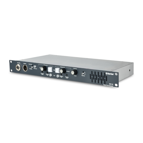
Clear-Com MA-704. The RM-702/RM-802-IM remote speaker/headset station allows selectable two- channel talking and/or listening on a Clear-Com intercom system. The operator can communicate on either of the channels separately or on both at once. Illuminated dual-action talk buttons provide electronic momentary or latching capability. -
Page 11: Operation
User Guide| RM-702/RM-802-IM The RM-702/RM-802-IM installs in a standard 19 in. (48.26 cm) equipment rack, using only one rack space. The station provides two 3-pin, XLR connectors for input and loop-through on each channel. Operation Normal operation of the RM-702/RM-802-IM requires access only to the front panel controls. - Page 12 User Guide| RM-702/RM-802-IM the talk function will turn off. In any case the talk function is activated all of the time the button is pressed. TALK INDICATION: The talk button illuminates yellow when a talk is activated and blue when talk is not active. CALL INDICATION: The call button will flash red when a call signal is received on that channel.
- Page 13 User Guide| RM-702/RM-802-IM 2.4.5 Program Send Level Control for Channel A and B Both channels A and B have a program send level control that sets the volume of program audio being sent to that channel when the program is activated. 2.4.6 Speaker On/Off Switch The switch marked speaker on/off is used to turn the speaker on and off.
-
Page 14: Installation
This section discusses the installation of the RM-702/RM-802-IM in an intercom system including typical applications, overall installation theory, detail of each connector, and adjustments. Installation Overview This section describes the Clear-Com concept of intercom line connection. The following subjects are discussed: Intercom line connection Line termination... - Page 15 User Guide| RM-702/RM-802-IM 1. Please observe anti-static procedures. The circuit cards can be damaged by static electricity. Please ground yourself and tools before touching any circuit cards. 2. Remove the cover of the RM-702/RM-802-IM. 3. On the main circuit board, locate the JP4 three-pin jumper. The jumper is located on the rightmost upper portion of the circuit card, when viewed from the front of the unit.
- Page 16 Variations in impedance on the line upset the null. All Clear-Com Intercom lines must be terminated. Care must be taken not to fail to terminate or to “double”-terminate a line. All unused intercom inputs must be terminated to keep the line drive circuits stable.
-
Page 17: Description Of Front Panel Connectors
3.3.1 Panel Mic Connector (Front Panel) Clear-Com provides two plug-in panel microphones for use on the RM-702/RM-802- IM. The GM-9 is 9 in. (22.86 cm) long and GM-18 is 18 in. (45.72 cm) long. The microphone is of the electret type. The microphone has a built-in 1/4 in. (0.64 cm) phone jack for a connector. -
Page 18: Description Of Rear Panel Connectors
IFB/Hot Mic (Rear Panel, 1/4-Inch Phone Jack) A 1/4 in. (0.64 cm) phone jack marked IFB/HOT mic provides an output signal from the selected microphone. This output is intended to work with Clear-Com’s MA-704 IFB control panel. A control signal into this connector from the MA-704 causes all active talks from the station to cease and only sends the IFB output. -
Page 19: Description Of Options And Adjustments
User Guide| RM-702/RM-802-IM Tip --- Microphone audio output Ring --- Control signal (>15 VDC) Sleeve --- Ground (shield) 3.4.3 Accessory (Rear Panel, DB-15F) The accessory DB-15F connector on the rear panel provides program input, announce audio output, announce relay contacts, and foot switch inputs for activating a talk on either channel. - Page 20 This will allow announcements to be made without being heard over the intercom channels. INTRPT EXT IFB: When the hot mic output is connected to Clear-Com’s IFB system and the interrupt external IFB switch is set to the on position, pressing a key on the IFB system will disconnect the selected headset or panel microphone from the intercom line(s).
- Page 21 User Guide| RM-702/RM-802-IM internal jumper. See the next section, “Re-Setting Program Interrupt Options,” for instructions. PROGRAM INTERRUPT B: Interrupts the program audio to channel B while a call signal is sent on channel B (default). You can change this option so that a talk signal, rather than a call signal, interrupts the program audio on channel B.
- Page 22 User Guide| RM-702/RM-802-IM 3. On the main circuit board, locate one of the following: a. For channel A: The JP5 three-pin jumper, located in the center of the circuit board. b. For channel B: The JP6 three-pin jumper, located in the center of the circuit board.
- Page 23 User Guide| RM-702/RM-802-IM To adjust the panel microphone gain, you must open the unit. Ground yourself and tools before touching the circuit board, as circuit boards can be damaged by static electricity. Remove the top cover of the unit, and locate the jumper labeled “R161.” It is located on the leftmost side of the circuit board, toward the front of the unit when facing it.
-
Page 24: Typical System Applications
Talent Announcer TR-50 Channel B The system has two 2-channel RM-702/RM-802-IM rack-mount stations. The system is powered from a Clear-Com power supply that also provides the terminations for both channels. Channel B is connected to talent receivers for announcers. Page 24... - Page 25 The system has several 2-channel RM-702/RM-802-IM rack mount stations and several wall mount 2-channel stations. The system is powered from a Clear-Com power supply that also provides the terminations for both channels. A line of single-channel beltpacks is connected to channel A. The beltpacks are used for the cameras and floor managers.
-
Page 26: Actual Applications
Inadequate sidetone adjustment 3.7.1 Intercom line wiring The intercom line wiring has several purposes in the Clear-Com system: Connection of the audio intercom signal between stations. Delivery of DC power for remote stations (such as the RM-702/RM-802-IM) to operate from. -
Page 27: Program Input
The PS-702 provides the DC power for the system and the line termination switches must be turned on. All Clear-Com Intercom lines must be terminated. Care must be taken not to fail to terminate or to “double”-terminate a line. All unused intercom inputs must be terminated to keep the line drive circuits stable. - Page 28 User Guide| RM-702/RM-802-IM 3. Use the large knob labeled “Program Volume,” located right next to the speaker on/off switch, to set the appropriate program volume level. This knob controls the program volume in the speaker/headphone. 4. Set either the A or B potentiometer marked Program Level, located under either the A or B channel’s volume knob, to the lowest setting.
- Page 29 User Guide| RM-702/RM-802-IM “ACCESSORY” CONNECTOR DB-15F Viewed from the rear of the unit Power (+30 VDC) – Program Input + Program Input 1. Connect a balanced input to pins #8 and #15 with the shield connected to pin #7. 2. To connect an unbalanced input, connect the signal to pin #8 and connect the shield to pins #15 and #7.
- Page 30 3.7.4 External IFB (MA-704 and PIC-4704 Connection) Clear-Com provides a stand-alone IFB system called a PIC-4704. The PIC-4704 provides four interruptible IFB feeds from two program sources, and is located in a central location. The MA-704 is a four-channel control head intended to work with the PIC-4704.
- Page 31 User Guide| RM-702/RM-802-IM microphone in use on the RM-702/RM-802-IM to the MA-704, muting any talks active on the RM-702/RM-802-IM. To connect the RM-702/RM-802-IM to an MA-704, use a two-wire shielded cable with 1/4 in. (0.64 cm) tip, ring, and sleeve jacks on each end. Connect the tip to the tip, the ring to the ring, and use the shield to connect the sleeve to the sleeve.
- Page 32 User Guide| RM-702/RM-802-IM 3.7.6 Remote Control of Talk Switches The talk switches of the RM-702/RM-802-IM can be remotely controlled with external contacts that are available on the accessory connector on the rear panel. A footswitch or remote pushbutton when wired to the accessory connector acts exactly the same as pushing a talk switch on the front panel.
- Page 33 User Guide| RM-702/RM-802-IM 3.7.7 Inadequate Side-tone Adjustment The receive circuits of the intercom channels have been optimized for an intercom line length of up to 1,000 ft (305 m). The capacitance of the intercom line must be compensated for in the receive circuits if a good sidetone null is to be achieved. When using a speaker, a good sidetone null is necessary to achieve a usable listening level.
-
Page 34: Maintenance
User Guide| RM-702/RM-802-IM Maintenance Introduction This chapter provides maintenance information. RM-702 Headset Headset Main XLR4 XLR4 Program Limiter Line Level Length Panel Sidetone Headset Null Limiter Jack Panel Mic Gain Listen Spkr Main On/Off Intercom Mute Program Line A Level A Line Length Sidetone... -
Page 35: Technical Specifications
User Guide| RM-702/RM-802-IM Technical Specifications RM-702/RM-802-IM Two-Channel Station dBu is an absolute measurement. 0 dBu is referenced to 0.775 volts RMS 5.1.1 Panel Microphone Input Input Type: Electret Input Impedance: >=2KΩ Mic Limiter Threshold: 0dBu ±3dB Mic Limiter Range: >= 20dB 5.1.2 Headset Microphone Input Input Type: Dynamic... - Page 36 User Guide| RM-702/RM-802-IM 5.1.7 Party Line Input Crosstalk: < -60dB Max level before Clipping: >= 12dBu Sidetone Null Capability: > 25dB 5.1.8 Stage Announce/Balanced Line Out Type: Balanced Output Impedance: >= 200Ω Load Impedance: >= 600Ω 5.1.9 IFB/Hot Mic Type: Unbalanced Output Impedance: 180Ω...
-
Page 37: Rear Panel Connectors
User Guide| RM-702/RM-802-IM 5.1.12 Noise Panel Mic - Party Line: < -65dBu Headset Mic - Party Line: < -70dBu Headset Mic - Line Out: < -55dBu Program Input - Party Line: < -85dBu Program Input - Headset Out: < -60dBu Program Input - Speaker Out: <... - Page 38 Weight: 5.2 lbs. (2.36 Kg) 5.1.23 Notice About Specifications While Clear-Com makes every attempt to maintain the accuracy of the information contained in its product manuals, that information is subject to change without notice. Performance specifications included in this manual are design-center specifications and are included for customer guidance and to facilitate system installation.
-
Page 39: Technical Support And Repair Policy
User Guide| RM-702/RM-802-IM Technical Support and Repair Policy To ensure that your experience with Clear-Com and our World Class products is as beneficial, effective and efficient as possible, we would like to define the policies and share some "best practices" that can accelerate any problem solving processes which we may find necessary and to enhance your customer service experience. - Page 40 Tel:+1 510 337 6600 Email:Support@Clearcom.com d. Email Technical Support is available for all Clear-Com branded products free of charge for the life of the product, or two years after a product has been classified as obsolete, whichever comes first. To log or update a request, send an email to: Support@Clearcom.com.
-
Page 41: Return Material Authorization Policy
The Customer will be provided with an RMA number upon contacting Clear-Com Sales Support as instructed below. c. The RMA number must be obtained from Clear-Com via phone or email prior to returning product to the Service Center. Product received by the Service Center without a proper RMA number is subject to return to the Customer at the Customer's expense. -
Page 42: Repair Policy
The Customer will be provided with an RA number upon contacting Clear-Com Customer Services as instructed below. c. The RA number must be obtained from Clear-Com via phone or email prior to returning product to the Service Center. Product received by the Service Center without a proper RA number is subject to return to the Customer at the Customer's expense. - Page 43 Clear-Com's designated location for repair. Clear-Com will pay for the equipment to be returned to the Customer when it is repaired under warranty Shipping from Clear-Com is normal ground delivery or international economy.
Need help?
Do you have a question about the RM-702-IM and is the answer not in the manual?
Questions and answers