Electrolux Built-in Wall Oven Service Manual
Built-in wall oven
Hide thumbs
Also See for Built-in Wall Oven:
- Service manual (65 pages) ,
- Use & care manual (44 pages) ,
- Tips and recipes (36 pages)
Table of Contents
Advertisement
Advertisement
Table of Contents

Subscribe to Our Youtube Channel
Related Manuals for Electrolux Built-in Wall Oven


Summary of Contents for Electrolux Built-in Wall Oven
- Page 1 Service Manual B u i l t - i n W a l l O v e n 318 202 104 (0311)
- Page 2 THIS IS A BLANK PAGE...
-
Page 3: Table Of Contents
Table of Contents SAFE SERVICING PRACTICES .......... 1 PRODUCT FEATURES ............2 WIRING DIAGRAM............... 3 SECTION A - INSTALLATION INSTRUCTIOS....4 FOR YOUR SAFETY ......................4 CLEARANCE AND DIMENSIONS ..................4 IMPORTANT NOTES TO THE INSTALLER ................ 5 IMPORTANT NOTE TO THE CONSUMER ................. 5 IMPORTANT SAFETY INSTRUCTIONS ................ - Page 4 Table of Contents SECTION C - SERVICE DATA........... 24 ES500 ELECTRONIC OVEN CONTROL................24 CONVECTION MODE ...................... 24 PREHEAT ......................... 24 NORMAL BAKE ........................ 25 CLEAN ..........................25 RACK SENSOR ........................ 25 CLEAN AND TIMED CLEAN ..................... 25 FIRST RISE ........................25 OVEN CALIBRATION .......................
- Page 5 Table of Contents SECTION D - REPLACEMENT OF PARTS ....... 32 HOW TO REMOVE THE OVEN FROM THE CABINET .......... 32 HOW TO REMOVE PANELS TO ACCESS TIMER, CONVECTION MOTOR, BLOWER MOTOR, LATCH MOTOR, LATCH ROD, OVEN TEMPERATURE PROBE, BOARD RELAY, SAFETY THERMOSTAT, LIGHT TRANSFORMER ..................
-
Page 6: Section C - Service Data
Section C - Service Data TO REM0VE AND REPLACE OVEN DOOR 1. Open the door to the fully opened position. 2. Pull up the lock located on each hinge support toward front of range. You may have to apply a little upward pressure on the lock to pull it up. 3. - Page 7 THIS IS A BLANK PAGE...
-
Page 8: Safe Servicing Practices
Electrolux Home Products cannot be responsible, nor assume any liability, for injury or damage of any kind arising from the use of this manual. -
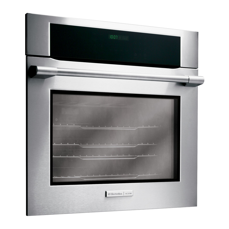
Page 9: Product Features
Product Features CONVECTION FAN CONTROL PANEL OVEN DOOR LATCH BROILING ELEMENT OVEN RACK SLIDERS OVEN RACK SUPPORT OVEN RACKS OVEN LIGHT BAKING ELEMENT GLASS OVEN DOOR DOOR HANDLE BROILER PAN BROILER PAN COVER... -
Page 10: Wiring Diagram
Wiring Diagram... -
Page 11: For Your Safety
Section A - Installation Instructions INSTALLATION AND SERVICE MUST BE PERFORMED BY A QUALIFIED INSTALLER. IMPORTANT: SAVE FOR LOCAL ELECTRICAL INSPECTOR'S USE. READ AND SAVE THESE INSTRUCTIONS FOR FUTURE REFERENCE. FOR YOUR SAFETY: Do not store or use gasoline or other flammable vapors and liquids in the vicinity of this or any other appliance. -
Page 12: Section A - Installation Instructios
Section A - Installation Instructions Volt, 60 Hz AC only electrical supply is required on a Important Notes to the Installer separate circuit fused on both sides of the line (time- Read all instructions contained in these installation delay fuse or circuit breaker is recommended). DO NOT instructions before installing the wall oven. -
Page 13: Electrical Connection
Section A - Installation Instructions Electrical connection If used in mobile homes or if local codes DO NOT permit connection of the frame grounding It is the responsibility and obligation of the consumer to conductor to the neutral (white) wire, separate contact a qualified installer to assure that the electrical the white and bare copper ground wires that extend installation is adequate and is in conformance with the... -
Page 14: Cabinet Installation
Section A - Installation Instructions Cabinet Installation The wall oven can tip when the door is open. The anti- tip brackets supplied with the wall oven must be attached to the cabinet and the appliance to prevent tipping of the wall oven and injury to persons. Anti-Tip Brackets Installation Instructions 1. -
Page 15: Typical Under Counter Installation Of An Electric Built-In Oven With An Electric Cooktop Mounted Above
Section A - Installation Instructions Side filler panels are necessary to iso- Only certain cooktop models may be installed late the unit from adjoining cabinets. over certain built-in electric oven models, listed Panel height should allow for installa- by the MFG ID number (see the insert sheet in- tion of approved cooktop models. -
Page 16: Typical Under The Counter Installation Of An Electric Built-In Oven With A Gas Cooktop Above
Section A - Installation Instructions 18”(45.7 cm) Max. 4”(10 cm) 5” Max. 6 1/2” Min. (12.7 cm) (16.5 cm) Flare Union Right Side of 120V/60Hz Cabinet Flexible Appliance Conduit Grounded Flare Outlet (To be Union accessible for Pressure shut-off valve Regulator operation) Cabinet sides or... -
Page 17: Section B - Electronic Oven Control
Section B - Electronic Controls CONTROL PAD FUNCTIONS Read the instructions carefully before using the oven. For satisfactory use of your oven, become familiar with the various functions of the oven as described below. Note: The graphics on your timer may look like one of those shown. Both are operating the same way. Bake Convection Bake Pad- Used Broil Pad- Used... -
Page 18: Setting The Clock
Section B - Electronic Controls SETTING THE CLOCK pad is used to set the clock. The clock may be set for 12 or 24 hour time of day operation. The clock has been preset at the factory for the 12 hour operation. When the range is first plugged in, or when the power supply to the range has been interrupted, the timer in the display will flash with "PF"... -
Page 19: Setting Continuous Bake Or 12 Hour Energy Saving
Section B - Electronic Controls SETTING CONTINUOUS BAKE OR 12 HOUR ENERGY SAVING pads control the Continuous Bake or 12 Hour Energy Saving features. The oven control has a factory preset built-in 12 Hour Energy Saving feature that will shut off the oven if the oven control is left on for more than 11 hours and 59 minutes. -
Page 20: Setting Oven Lockout Feature
Section B - Electronic Controls SETTING OVEN LOCKOUT FEATURE pad controls the Oven Lockout feature. The Oven Lockout feature automatically locks the oven door and prevents the Warmer Drawer from being turned on. It does not disable the clock, Timer, electric and gas surface burners, Warmer Zone or the interior oven lights. -
Page 21: Setting Silent Control Operation
Section B - Electronic Controls SETTING SILENT CONTROL OPERATION pads control the Silent Control operation feature. The Silent Control operation feature allows the oven control to be operated without sounds or beeps whenever necessary. If desired the control can be programmed for silent operation and later returned to operating with all the normal sounds and beeps. -
Page 22: Preheating
Section B - Electronic Controls PREHEATING pad controls the Preheat feature. The Preheat feature will bring the oven up to temperature and then indicate when to place the food in the oven. Use this feature in combination with the Bake pad when recipes call for preheating. Preheating is not necessary when roasting or cooking casseroles. -
Page 23: Baking
Section B - Electronic Controls BAKING pad controls normal baking. If preheating is necessary, refer to the Preheat Feature for instructions. The oven can be programmed to bake at any temperature from 170° F to 550° F (The sample shown below is for 350°F). To set the Bake Temperature to 350°F: 1. -
Page 24: Convection Baking
Section B - Electronic Controls CONVECTION BAKING pad controls the Convection Bake feature. Use the Convection Bake feature when cooking speed is desired. The oven can be programmed for Convection baking at any temperature between 300° F (149° C) to 550° F (288° C). To set the oven for Convection Bake and temperature to 350°F: 1. -
Page 25: Setting Timed Bake Or Timed Convection Bake
Section B - Electronic Controls SETTING TIMED BAKE OR TIMED CONVECTION BAKE ) or ) and ) pads control the Timed Bake feature. The automatic timer of the Timed Bake feature will turn the oven OFF after cooking for the desired amount of time you selected. -
Page 26: Setting Delayed Timed Bake Or Delayed Timed Convectionbake
Section B - Electronic Controls SETTING DELAYED TIMED BAKE OR DELAYED TIMED CONVECTION BAKE ) or ) and ) pads control the Delayed Time Bake feature. The automatic timer of the Delayed Time Bake will turn the oven on and off at the time you select in advance. NOTE: If your clock is set for normal 12 hour display mode the Delayed Time Bake feature can never be set to start more than 12 hours in advance. -
Page 27: Broil
Section B - Electronic Controls BROIL pad controls the Broil feature. When broiling, heat radiates downward from the oven broiler for even coverage. The Broil feature is preset to start broiling at 550°F however, the Broil feature temperature may be set between 400°F and 550°F. The broil pan and broil pan insert used together allow dripping grease to drain and be kept away from the high heat of the oven broiler. -
Page 28: Convection Roast
Section B - Electronic Controls CONVECTION ROAST pad controls the Convection Roast feature. The oven can be programmed to Convection Roast at any temperature between 300°F (149°C) to 550°F (288°C) (The example below is for 350°F). To Set the Convection Roast and temperature to 350°F: 1. -
Page 29: Starting Self-Clean Cycle
Section B - Electronic Controls STARTING SELF-CLEAN CYCLE pad controls the Self-Cleaning feature. If you are planning to use the oven directly after a self-clean cycle remember to allow time for the oven to cool down and the oven door to unlock. This normally takes about one hour. So to self-clean for 3 hours will actually take about 4 hours to complete. -
Page 30: To Start The Delayed Self-Clean Cycle
Section B - Electronic Controls TO START THE DELAYED SELF-CLEAN CYCLE pads and length of clean cycle, controls the Delayed Self- Clean operation. The automatic timer will turn the oven on and off at the time you select in advance. Be sure to review TO START THE SELF-CLEAN CYCLE for recommended clean times. -
Page 31: Es500 Electronic Oven Control
Section C - Service Data ES500 ELECTRONIC OVEN CONTROL 1. This self-cleaning controler offers Bake, Broil, Preheat, Convection Bake and Convection Roasting modes, Timed and Delayed Baking, and Cleaning functions. 2. Convection operates with an element and a fan dedicated to convection. 3. -
Page 32: Normal Bake
Section C - Service Data NORMAL BAKE During a normal bake mode, the controler preheats the oven with the bake element. When the desired temperature is reached, the controler adds top heat by cycling the broil element on for 12 to 18 seconds per minute . The bake element is on for the remaining time of the minute. -
Page 33: Electronic Oven Control Fault Code Descriptions
Section C - Service Data ELECTRONIC OVEN CONTROL FAULT CODE DESCRIPTIONS Note: Only three fault codes are displayed by this control “F1”, “F2”, "F3" and “F9”. Generally speaking “F1” implies a control failure, "F2" is a communication problem, “F3” an oven probe problem, and “F9” a latch motor problem. In all occurrences the alarm is accompanied by a display of “F1“. -
Page 34: Rtd Scale And Oven Temperature Sensor
Section C - Service Data RTD SCALE AND OVEN TEMPERATURE SENSOR Temp. °F Temp. °C Resistance (ohms) OVEN TEMPERATURE 32 ± 1.9 0.0 ± 1.1 1000 ± 4.0 SENSOR 75 ± 2.5 23.9 ± 1.4 1091 ± 5.3 250 ± 4.4 121.1 ±... -
Page 35: Auxiliary Board
Section C - Service Data AUXILIARY BOARD The auxiliary board controls the convection element and the 2 speeds of the blower. EXPLODED VIEW OF CONVECTION SYSTEM MOUNTING PLATE CONVECTION FAN MOTOR ASSEMBLY OVEN CAVITY FAN NUT CONVECTION ELEMENT CONVECTION FAN BLADE CONVECTION FAN COVER FAN COVER... -
Page 36: Fan Blade
Section C - Service Data FAN BLADE The fan blade is mounted in the rear of the unit and has a "D" shaped mounting hole. Only minimum clearance exists between the oven back, fan blade, and fan shroud. Be careful not to bend blade when removing or installing. -
Page 37: Fan Relay
Section C - Service Data FAN RELAY The fan motor runs continuously while in the convection mode unless the door is opened. If the fan does not operate, check the following: • Display illuminated on the electronic control. • Voltage output between terminals P5-7 and Neutral. •... -
Page 38: Light Transformer
Section D - Replacement of parts 1.0 HOW TO REMOVE THE OVEN FROM THE CABINET 1. Disconnect wall oven from electrical supply. 2. Insert tool supplied with the appliance both side at the same time in the hole located on the side frame and visible when the oven door is opened. -
Page 39: How To Replace The Electronic Oven Control
Section D - Replacement of parts 3.0 HOW TO REPLACE THE ELECTRONIC OVEN CONTROL 1. Disconnect wall oven from electrical supply. 2. Remove wall oven from the cabinet. (section 1.0) 3. Remove the panels to access oven control. (section 2) 4. -
Page 40: How To Replace The Convection Motor
Section D - Replacement of parts 4.0 HOW TO REPLACE CONVECTION MOTOR 1. Disconnect wall oven from electrical supply. 2. Remove wall oven from the cabinet. (section 1.0) 3. Remove the back panel to access convection motor. (section 2.0) 4. By the inside of the oven remove the 3 screws holding the convection fan cover. -
Page 41: How To Replace The Blower Motor
Section D - Replacement of parts 5.0 HOW TO REPLACE THE BLOWER MOTOR 1. Disconnect wall oven from electrical supply. 2. Remove wall oven from the cabinet. (section 1.0) 3. Remove the back panel. (section 2.0) 4. Remove the top panel. (section 2.0) 5. -
Page 42: How To Replace The Oven Temperature Probe
Section D - Replacement of parts 7.0 HOW TO REPLACE THE OVEN TEMPERATURE PROBE 1. Disconnect wall oven from electrical supply. 2. Remove wall oven from the cabinet. (section 1.0) 3. Remove the back panel. (section 2.0) 4. Unplug the quick connect from the temperature probe. (Figure 13) Figure 13 5. -
Page 43: How To Replace The Safety Thermostat
Section D - Replacement of parts 9.0 HOW TO REPLACE THE SAFETY THERMOSTAT 1. Disconnect wall oven from electrical supply. 2. Remove wall oven from the cabinet. (section 1.0) 3. Remove the top panel. (section 2.0) 4. Remove the 2 screws holding the safety thermostat. (Figure 16) 5. -
Page 44: How To Replace The Broil Element
Section D - Replacement of parts 11.0 HOW TO REPLACE THE ELEMENTS (CONTINUED) 11.2 HOW TO REPLACE THE BROIL ELEMENT 1. Disconnect wall oven from electrical supply. 2. By the inside of the oven, remove the 2 screws holding the broil element. (Figure 19) 3. -
Page 45: How To Replace The Oven Light
Section D - Replacement of parts 12.0 HOW TO REPLACE THE OVEN LIGHT 1. Disconnect wall oven from electrical supply. 2. By the inside of the oven, remove the oven light cover by pulling out on one side at the time. (Figure 22) Figure 22 3. -
Page 46: How To Remove The Door From The Oven
Section D - Replacement of parts 14.0 HOW TO REMOVE THE DOOR FROM THE OVEN 1. Disconnect wall oven from electrical supply. 2. Open the door to the fully opened position. (Figure 25 3. Pull the lock located on each hinge support toward front of appliance. -
Page 47: How To Replace The Oven Gasket
Section D - Replacement of parts 16.0 HOW TO REPLACE THE OVEN GASKET 1. Disconnect wall oven from electrical supply. 2. Remove the oven door from the apppliance. (section 14.0) 3. The oven gasket is clipped. To remove it pull on each clip. -
Page 48: How To Replace The Hinge
Section D - Replacement of parts 17.0 HOW TO REPLACE A GLASS OF THE OVEN DOOR (CONTINUED) 5. Remove others glass by slidingdown one glass at the time. (Figure 31) 6. Replace the glass and reassemble in reverse order. Figure 31 18.0 HOW TO REPLACE THE HINGE 1. - Page 49 Section D - Replacement of parts 19.0 HOW TO REPLACE THE HANDLE (CONTINUED) 4. Remove the 2 screws. (Figure 34) 5. Replace the handle and reassemble in reverse order. Figure 34...
-
Page 50: Section E - Exploded View Drawings
Section E - Exploded view drawings CONTROL PANEL EXPLODED VIEW... -
Page 51: Control Panel Part Description
Section E - Exploded view drawings CONTROL PANEL PART DESCRIPTION Position No Part No Description 318244900 Panel, Control assy, Glass, Black w/Membrane 316272220 Controller, Electronic, ES500 38240500 Panel, Glass Trim, Stainless 318240800 Bracket, Timer Mtg, (2) 5303324184 Screw, 8-18 x 5/16, Black, (4) 318237200 Housing, Top/Control 318237300... -
Page 52: Body Exploded View
Section E - Exploded view drawings BODY EXPLODED VIEW... -
Page 53: Body Part Description
Section E - Exploded view drawings BODY PART DESCRIPTION Position No Part No. Description 318066411 Panel, Main Back 318236400 Shield, Oven Top 318240100 Shelf, Oven, Fixed 318219500 Rack, Broiler Pan 318240200 Shelf, Oven, Extendable 318240000 Glide & Support assy, Oven Shelves, RH 318240001 Glide &... - Page 54 Section E - Exploded view drawings BODY EXPLODED VIEW...
- Page 55 Section E - Exploded view drawings BODY PART DESCRIPTION Position No Part No. Description 318219402 Cover, Fan 107* 5304415832 Screw, 8-18 x 0.406 108# 318073017 Motor, Blower 316136400 Blade, Fan 316136600 Nut, Fan Retainer 119# 318004900 Switch, Thermal 125# 318137310 Motor, Convection 125* 318142100...
-
Page 56: Door Exploded View
Section E - Exploded view drawings DOOR EXPLODED VIEW... -
Page 57: Door Part Description
Section E - Exploded view drawings DOOR PART DESCRIPTION Position No Part No. Description 318238201 Trim, Oven Door, Black, Top 318238300 Holder, Glass, Top 318237800 Glass, Door Front, Black 318238000 Glass, Door, Middle 5303325168 Screw, 10-32 x 5/8, Handle Mtg 5303320422 Screw, 6-20 x 5/16, Black, (6) 318240400... - Page 58 THIS IS A BLANK PAGE...
Need help?
Do you have a question about the Built-in Wall Oven and is the answer not in the manual?
Questions and answers