Table of Contents
Advertisement
Quick Links
- 1 Instructions for Ordering Repair Parts
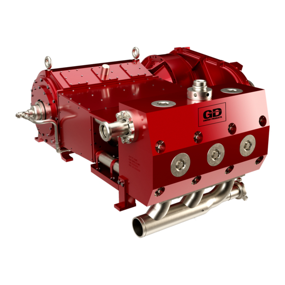
- 2 Figure 2-1 Gd 3000 Pump
- 3 Section 2, Design, Description and Specifications
- 4 Figure 2-2 Gd 3000 Power End
- 5 Figure 2-5 Gd 3000 Fluid End
- 6 Section 3, Preparation, Operation and Maintenance
- 7 Section 6, Rebuilding Data, Recommended Running Clearances and Torques
- Download this manual
Advertisement
Table of Contents

Related Manuals for Gardner Denver GD-3000


Summary of Contents for Gardner Denver GD-3000
- Page 1 3-1-618 Revision D GARDNER DENVER ® April 2011 WELL SERVICING PUMP MODEL GD-3000 OPERATING AND SERVICE MANUAL ECN 1058968...
-
Page 2: Instructions For Ordering Repair Parts
Reliability in materials and quality assurance is incorporated in our genuine replacement parts. Your authorized Gardner Denver Sales Office offers all the backup you’ll need. The Tulsa Manufacturing Facility maintains a large inventory of genuine parts. -
Page 3: Foreword
FOREWORD Gardner Denver® pumps are the result of advanced engineering and skilled manufacturing. To be assured of receiving maximum service from this pump the owner must exercise care in its operation and maintenance. This book is written to give the operator and maintenance personnel essential information for day-to-day operation, maintenance and adjustment. -
Page 4: Table Of Contents
TABLE OF CONTENTS Maintain Pump Reliability and Performance with Genuine Gardner Denver Parts and Support Services ......................i Instructions For Ordering Repair Parts .................. i Foreword..........................ii Index............................. iv List of Illustrations ......................... v Section 1, Danger Notices..................... 1 Section 2, Design, Description and Specifications ..............9 Section 3, Preparation, Operation and Maintenance.............. -
Page 5: Index
INDEX Crankshaft Assembly........26 Performance Rating........14 Crosshead Assembly …......24 Periodic Routine Maintenance Schedule..18 Crosshead Guide and Tie Rods …....25 Plunger / Packing Lubrication ......17 Daily Routine Maintenance Schedule..19 Plunger Packing Lubrication Recommendation DANGER NOTICES, SECTION 1....1 Chart ............ -
Page 6: List Of Illustrations
LIST OF ILLUSTRATIONS Figure # Description Page Figure 2-1 GD 3000 Pump..................9 Figure 2-2 GD 3000 Power End ................10 Figure 2-3 GD 3000 Power End Top View............... 11 Figure 2-4 GD 3000 Gear Reduction Unit ............... 12 Figure 2-5 GD 3000 Fluid End ................ -
Page 7: Section 1, Danger Notices
Alterations to the pump, or • Wear safety shoes and safety glasses. application of the pump outside the limits, must not be made without Gardner Denver • Alert other personnel to move away written approval, together with a new set of from the area. -
Page 8: Covers And Guards
Carefully swing the hammer to avoid Wipe their hands and the hammer • • striking themselves, another person and handle and maintain a firm grip on the objects other than the targeted lugs or handle to avoid losing control of the hammer bar. -
Page 9: Pressurized Pump Systems
as fully assembled should be separated into smaller loads. DANGER For these smaller loads the lifting devices should be fastened to the lifting attachments normally built into the individual motor, Failure to follow safe and proper engine, pump or transmission / torque pump, pump package or component converter, or their separate support skids. - Page 10 Before starting the pump every time, Operating a pump against a blocked or check to insure: restricted discharge line produce The pressure relief valve is in good • excessive pressures in the entire discharge operating condition and has been set to system, which damage...
-
Page 11: Flammable, Hot, Cold Or Corrosive Fluid Pumping
Contact discharge piping, welding these a Gardner Denver service representative for components is not recommended. assistance in selecting the proper packing welding on the discharge system cannot be before beginning operation. avoided, only experienced, qualified welders should be used. -
Page 12: High Pressure Liquid Jetting Blasting And Cleaning
Never operate a pump which is pumping on these vapors even after the engine fuel hydrocarbons or other flammable, hot, cold, line is shut-off if an air inlet shut-off is not or corrosive fluids when any part of the used. pump, suction system or discharge system is leaking. - Page 13 High pressure fluid from hand held or hand Before the equipment is started, the work directed pressure and flow directing devices area must be inspected and properly may overpower an operator’s ability to prepared to avoid personal injury, death, control or direct the device, which could and/or damage to equipment.
- Page 14 Before purchasing wands, nozzles, guns, connections, hoses, etc., manufacturers of these components should be contacted for detailed information on the design and safety features incorporated their products. After careful study of various manufacturers products, we recommend that only those wands, nozzles, guns, connections and hose, etc., be considered for purchase that you judge to offer the highest quality of design, construction and...
-
Page 15: Section 2, Design, Description And Specifications
DESIGN, DESCRIPTION AND SPECIFICATIONS INTRODUCTION Therefore, in the beginning of this manual The new Gardner Denver GD 3000 is a high the user is introduced to dangers inherent in horsepower, high rod load multi-purpose the operation of a high pressure pump. To... -
Page 16: Figure 2-2 Gd 3000 Power End
Section 3, "Pump Preparation, Operation, bearings, recommended fastener and Maintenance," addresses the issues of torques. preparing the pump for operation after shipping or storage, the lubrication system PUMP DESIGN design and specifications, the new pump run-in procedures, and the periodic routine The GD 3000 pump uses three major maintenance schedule. -
Page 17: Figure 2-3 Gd 3000 Power End Top View
FIGURE 2-3 GD 3000 Power End Top View but utilizes a large knuckle (7”) and crosshead (13.5”), thus allowing extremely NOTICE high rod load (350,000 lbf.). (See FIGURE 2-3). The direction of rotation must be such that top side of the Also, the pump has a drain pan to collect crankshaft is moving towrd the fluid other... -
Page 18: Figure 2-4 Gd 3000 Gear Reduction Unit
the forward end of each cylinder in the POWER END AND GEAR REDUCTION bottom of the crosshead guide. These three UNIT LUBE SYSTEM (FIGURE 2-2, drains are combined together and empty FIGURE 2-3, and FIGURE 2-4,) into the main drain external to the frame. Both the gear reduction unit and power end The gear reduction unit has one inlet have individual lube oil inlets. -
Page 19: Figure 2-5 Gd 3000 Fluid End
FLUID END (FIGURE 2-5) ment terms valve spring performance. Improvements in the fluid end This fluid end incorporates a modern life come from increasing fluid cylinder cross sections in areas of maximum through stud design, which eliminates the stresses and new high quality low sulfur, weight of the traditional flange fluid ends higher nickel and molybdenum content and simplifies installation and removal of tie... -
Page 20: General Specifications
GENERAL SPECIFICATIONS This section presents the pump basic specifications. The first set of specifications deals with the pump's power, rod load, plunger stroke, and overall dimensions. The other table presents allowable pressures and flows for various pump speeds along with data on power requirements. GD 3000 PERFORMANCE RATING Rated Brake Horsepower 3000 bhp... -
Page 21: Section 3, Preparation, Operation And Maintenance
SECTION 3 PREPARATION, OPERATION AND MAINTENANCE Coat the gear reducer input shaft and all extension rods with a heavy rust DANGER preventive. Plug drain holes at the bottom of the Read and understand clearly all pump frame, crosshead guide, gear safety rules and precautions before reducer transition and offset. -
Page 22: Lube Pump Suction Piping Sizing And Requirements
Maintaining a slight amount of upward At maximum operating speed the tension on the fluid end, check the gap vacuum reading at the lube pump inlet beneath the fluid end supports. must be no more than 8" hg or 4 psi or 0.28 bar. -
Page 23: Figure 3-1 Lubricant Recommendations
listed grade of oil for various inlet or sump temperature ranges. FIGURE 3-1 Lubricant Recommendations charge when the triplex pump operates at its PLUNGER / PACKING LUBRICATION maximum flow. The fluid end plungers are lubricated from a separate lubrication pump through the The first startup and several hours of the pump stuffing box. - Page 24 the following guidelines are presented for the 12. Run the pump at 80-90 strokes per min maintenance personnel to follow during the at the following loads: critical startup and break-in period: 40% of full rated load 30 min 60% of full rated load 30 min Fill lube...
- Page 25 PERIODIC ROUTINE MAINTENANCE Check the plunger/packing lubrication SCHEDULE pump for proper operation. Insure packing nut is tightened sufficiently into stuffing box. Recheck tightness after Performance periodic routine maintenance tasks, described this extended continuous operation. section, will ensure long, economical, and trouble free operation of this pump.
- Page 26 PLUNGER PACKING LUBRICATION RECOMMENDATION CHART ROCK DRILL LUBRICANTS - NORMAL CONDITIONS Source Type Pour Point Maximum Amoco Amoco Rock Drill Oil - Light -20°F Amoco Rock Drill Oil - Medium 0°F Arco Air Drill #147 0°F Arco Trueslide #150 15°F Chevron Oil U.S.A.
-
Page 27: Section 4, Service Procedures
SECTION 4 SERVICE PROCEDURES This section describes various assembly FLUID END SERVICE and disassembly procedures necessary for pump servicing or parts replacement. The This discussion starts with the description of General Requirements and Safety Rules steps necessary for removal and installation section is a reminder for the maintenance of the fluid cylinder assembly and proceeds personnel of the critical importance of safety... -
Page 28: Figure 4-1 Tightening Sequence For Fluid End Nuts
Plunger and Packing Replacement NOTICE This service procedure can be performed with the fluid cylinder in place on the pump, procedure fluid and consists of the following steps: installation is presented separately due to the special and critical nature Remove the suction cover retainer nut of the connection between the power with the appropriate male hex wrench. - Page 29 11. Install and hand tighten the packing nut Install the stuffing box seal, lubricating to align the packing in the bore. with a light coat of grease. 12. Loosen the packing nut to allow for Lubricate the stuffing box threads with installation of the plunger.
-
Page 30: Crosshead Assembly
Oil Stop Head Seal Retainer and and a seat puller jack. These tools are Crosshead Guide End Plate (FIGURE 2-2 available from Gardner Denver. and FIGURE 2-3) Clean the valve seat deck thoroughly. Remove the fluid end following the procedure described in "Fluid End... -
Page 31: Figure 4-3 Crosshead Assembly
FIGURE 4-3 Crosshead Assembly Remove journal bearings from the rod 16. Remove the wrist pin while supporting the and rod cap. crosshead back half. Slide crosshead assembly 17. Remove the crosshead back half from the forward until journal end of rod is ready to connecting rod. -
Page 32: Crankshaft Assembly
Using the tie rod wrench (refer to the Crankshaft Assembly Special Tools section in the Parts Manual) remove the tie rod. Note: the Remove the pump from the trailer and tie rod should be supported either with move it to service area. The pump a hoist or another technician. - Page 33 14. Lift the crankshaft until it is free of all main bearings. Continue until bearing faces of crankshaft reaches next WARNING bearing. If crankshaft does not slip When reassembling the crankshaft through bearings freely, push rollers into race. If bearings are extremely assembly, make sure to follow these loose and worn, it may be necessary to steps:...
-
Page 34: Section 5, Trouble-Shooting
SECTION 5 TROUBLE-SHOOTING PROBLEM POSSIBLE CAUSE SUGGESTED ACTION Pump Overloads Driver. 1. Excessive pump speed 1. Reduce pump speed and/or and/or discharge pressure. pressure. 2. Blockage or closed 2. Clean or open valve. valve in discharge line. 3. Incorrect plunger size. 3. - Page 35 PROBLEM POSSIBLE CAUSE SUGGESTED ACTION Cavitation, Fluid Knock 1. Improper suction system 1. See recommended system or Hammer. layout. layout in manual. 2. Low suction pressure. 2. See Low Suction Pressure problem. 3. Suction stabilizer and 3. Install suction stabilizer pulsation damper not used.
- Page 36 PROBLEM POSSIBLE CAUSE SUGGESTED ACTION Knock In Power End. 1. Improper main bearing 1. Check and adjust clearance. clearances. 2. Incorrect pump rotation. 2. Reverse rotation. 3. Loose plunger coupling. 3. Check and tighten. Replace if damaged. 4. Loose bearing housings/ 4.
- Page 37 PROBLEM POSSIBLE CAUSE SUGGESTED ACTION Oil Seal Leakage. 1. Worn sealing lip. 1. Replace seal. 2. Damaged sealing lip. 2. Replace seal. 3. Outside diameter not seated. 3. Clean and polish bore of oil seal housing. 4. Shaft rough at seal lip. 4.
- Page 38 PROBLEM POSSIBLE CAUSE SUGGESTED ACTION Short Plunger/Packing Life. 1. Abrasives in pumped fluid. 1. Consult Gardner Denver Customer Service for plunger/ packing recommendation. Filter pumped fluid. 2. Excessive plunger/packing 2. Lubricate with rock drill oil. friction. Do not overtighten adjust- able packing.
- Page 39 4. Corrosive attack by pumped 4. Treat fluid or use corrosion fluid. resistant studs. 5. Studs damaged before 5. Check condition before installation. installation, and replace if necessary. 6. Low strength studs. 6. Use Gardner Denver studs. 3-1-618 Page 33...
-
Page 40: Section 6, Rebuilding Data, Recommended Running Clearances And Torques
SECTION 6 REBUILDING DATA, RECOMMENDED RUNNING CLEARANCES AND TORQUES REBUILDING DATA FOR GD 3000 PUMP (in.) PUMP STROKE 11 Inches Crankshaft Throw Diameter..........7.7485/7.7500 Crankshaft Shaft Diameter at Main Bearings..... 19.000/19.002 Distance Between Main Bearing Centers......14.00 Bore in Frame for Inner Main Bearings......22.446/22.448 Bore in Frame for Outer Main Bearings ...... -
Page 41: Torques
RECOMMENDED TORQUES VALUES FOR GD-3000 FOOT POUNDS_________ DESCRIPTION FASTENER WITH LOCTITE WITH ANTISEIZE Plunger Clamp Bolts……………………………….. 1/2”-13 Main Bearing Retainer Bolts....... ½”-13 Thrust Bearing Retainer ........5/8”-11 Crosshead Guide to Pump Frame ...... 3/4”-10 Crankshaft Bearing to Pump Frame ....3/4”-10 Suction Manifold to Fluid End...... -
Page 42: Product Warranty
BE-13 R 02/2003, Copyright © 2003 Gardner Denver, Inc. GENERAL PROVISIONS AND LIMITATIONS Gardner Denver (the "Company") warrants to each original retail purchaser ("Purchaser") of its new products, assemblies or parts from the Company or its authorized distributors that such products are, at the time of delivery to the Purchaser, made with good material and workmanship. - Page 43 LABOR TRANSPORTATION AND INSPECTION The Company will provide labor, by Company representative or authorized service personnel, for repair or replacement of any product or part thereof which in the Company's judgment is proved not to be as warranted. Labor shall be limited to the amount specified in the Company's labor rate schedule. Labor costs in excess of the Company rate schedules caused by, but not limited to, location or inaccessibility of the equipment, or labor provided by unauthorized service personnel is not provided for by this warranty.
- Page 44 Company prior to shipment. All requests for product return shall be submitted by email. Facsimile or letter to: Warranty Department c/o Gardner Denver Petroleum Pumps 4747 South 83 East Avenue Tulsa, Oklahoma 74145 Email: CCR.QAR@gardnerdenver.com Facsimile: (918) 664-6225 BE-13 R 02/2003, Copyright © 2003 Gardner Denver, Inc. 3-1-618 Page 38...
Need help?
Do you have a question about the GD-3000 and is the answer not in the manual?
Questions and answers