
Subscribe to Our Youtube Channel
Related Manuals for Gardner Denver GD-2250T


Summary of Contents for Gardner Denver GD-2250T
- Page 1 GARDNER DENVER ® 301THD996 Revision D April 2011 GD-2250T WELL SERVICING PUMP OPERATING AND SERVICE MANUAL ECN 1058968...
- Page 2 GD-2250T WELL SERVICING PUMP MAINTAIN PUMP RELIABILITY AND PERFORMANCE WITH GENUINE GARDNER DENVER PARTS AND SUPPORT SERVICES ® Gardner Denver genuine pump parts are manufactured to design tolerances and are developed for optimum dependability. Design and material innovations are the result of years of experience with hundreds of different pump applications.
- Page 3 FOREWORD Gardner Denver® pumps are the result of advanced engineering and skilled manufacturing. To be assured of receiving maximum service from this pump the owner must exercise care in its operation and maintenance. This book is written to give the operator and maintenance personnel essential information for day-to-day operation, maintenance and adjustment.
- Page 4 TABLE OF CONTENTS Maintain Pump Reliability and Performance with Genuine Gardner Denver Parts and Support Services ......................i Instructions for Ordering Repair Parts ................... i Foreword..........................ii Index............................. iv List of Illustrations ......................... v Section 1, Danger Notices..................... 1 Section 2, Design, Description and Specifications ..............9 Section 3, Preparation, Operation and Maintenance..............
- Page 5 Monthly Routine Maintenance Schedule ..17 Warranty ............. 35 Oil Stop Head Seal & Gear Covers.... 23 Wedge Puller, Danger Notice ......2 Performance Rating, GD-2250T ....12 Periodic Routing Maintenance Schedule..17 Plunger/Packing Lubrication ....... 16 Plunger Packing Lubrication Recommendation Chart ...... 19...
- Page 6 Figure # Description Page Figure 2-1 GD-2250T Pump ..................9 Figure 2-2 GD-2250T Power End Section A-A ............10 Figure 2-3 Fluid End ....................11 Figure 3-1 Power End Mounting Hole Pattern ............13 Figure 3-2 Alternate Power End Mounting Hole Pattern .......... 14 Figure 3-3 Power End Lubricant Recommendations..........
-
Page 7: Section 1, Danger Notices
SECTION 1 DANGER NOTICES The timely replacement of expendable parts DANGER and any other worn or damaged parts can prevent equipment damage and possible injury. The original parts used in Gardner Read understand following Denver pumps are designed and tested to DANGER NOTICES before moving or exacting standards to provide high quality operating the pump or any pump package... - Page 8 Wipe their hands and the hammer Fully engage the wedge to prevent it • • handle and maintain a firm grip on the from disengaging violently from the handle to avoid losing control of the cover as a blow is struck. hammer while swinging and striking.
- Page 9 301THD996 Page 3...
- Page 10 DANGER For these smaller loads the lifting devices should be fastened to the lifting attachments normally built into the individual motor, Failure to follow safe and proper engine, pump or transmission / torque pump, pump package or component converter, or their separate support skids. lifting or moving procedures can lead to personal injury, death and /or When lifting subassembled components, for...
- Page 11 system, which damage burst Any pipe line used to direct pressurized • discharge system components. relief flow to another location, such as a collecting tank, is not blocked. DANGER The discharge system is not blocked • and all the discharge line valves are open.
- Page 12 leakage and do not operate the pump until Fluid end component inspections should the cause of the leak has been corrected. Replace any parts which are found to be be performed more frequently than every damaged or defective. When a gasketed six months if pressures above 2500 psi joint is disassembled for any reason, discard are used in the discharge system or if...
- Page 13 Pressure Equipment Directive 97/23/EC. 301THD996 Page 7...
- Page 14 times when the pump is operating. If the DANGER pumped fluid releases harmful, explosive or flammable vapors the covers must be vented to conduct the fumes away from Extreme caution must be exercised the pump unit to a non-hazardous area. by trained and experienced operators when flammable,...
- Page 15 HIGH PRESSURE LIQUID JETTING, systems. The pressurized stream can cause serious personal injury or death and BLASTING AND CLEANING can also change valve or control settings which could dangerously increase the delivery pressure to the pressure and flow DANGER directing device. When operating a pressure and flow Extreme caution must be exercised if directing device, use only equipment which...
- Page 16 equipment from the work area before inspection each time before operation is beginning operation. restarted. All pressure containing devices including Before purchasing wands, nozzles, guns, wands, nozzles, guns, hoses, connections, connections, hoses, etc., manufacturers of etc., should be regularly checked for these components should be contacted for condition.
-
Page 17: Section 2, Design, Description And Specifications
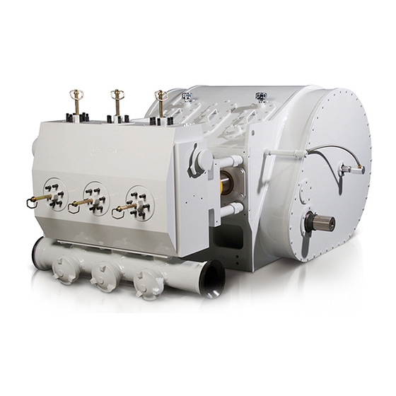
American Gear Manufactures sectional drawings. Association. The Issue of personnel safety is the most important topic covered in this manual. Note: The above figure shows a GD-2250T pump assembly with a 5.5” Fluid End FIGURE 2-1: GD-2250T PUMP 301THD996 Page 11... - Page 18 PUMP DESIGN POWER END The power end is available in 6.353:1 gear The GD-2250T is a horizontal single acting ratio only. This is a “dry sump” pump 2250 horsepower triplex pump. It has an 8” designed pressure lubrication stroke and various plunger sizes from 3.75”...
- Page 19 sophisticated methods CRANKSHAFT metallurgical control which enable us to obtain steel with very consistent The crankshaft is made of high strength chemical components and mechanical alloy steel that has been precision machined properties. This results in extended and heat treated for fatigue resistance and cylinder life.
- Page 20 The other table presents allowable pressures and flows for various plunger sizes and pump RPM’s along with data on power requirements. GD-2250T PUMP SPECIFICATIONS (U.S. SYSTEMS) Rated Brake Horsepower (hp) 2250...
-
Page 21: Section 3, Preparation, Operation And Maintenance
SECTION 3 PREPARATION, OPERATION AND MAINTENANCE Coat the gear reducer input shaft and all exposed bare metal with heavy rust DANGER preventive. Plug drain holes at the bottom of the Read and understand clearly all pump frame, at the rear of the pump, safety rules and precautions before and the gear reducer drain. - Page 22 Select proper number Bolt or weld brackets to sub-structure. thickness of shims to fill the gap under To bolt brackets use 7/8” - 9UNC the high foot. Note it is better to use Grade 8 bolts. shims up to .005” too thick than to leave any gap under the foot.
- Page 23 Lube System Pump Warning devices to monitor lube oil pressure and temperatures are highly recommended. triplex pump A positive displacement pump must be used. Gear type pumps have demonstrated operates at very high rod loads and reliable performance for similar applications pressures, and malfunction of the lube system may result in serious damage in the past.
- Page 24 FIGURE 3-3: Lubricant Recommendations Page 16...
- Page 25 Start the engine at the lowest PLUNGER / PACKING LUBRICATION possible RPM and operate pump at minimum pressure (< 100 psi). Make The fluid end plungers are lubricated from a sure that roller bearings, separate lubrication pump through the crossheads, knuckle joints, stuffing box.
- Page 26 Shut the pump down and let it cool Periodically monitor lube oil operating thoroughly before starting normal pressure temperature. operation of the pump. maximum lube operating temperature depends on a particular During the shutdown, change the oil grade of oil used in the pump lube filter elements and clean the suction system.
- Page 27 Clean the lube system strainer and Check all pressure, temperature, and replace the oil filter elements. vacuum gages for proper operation and replace as necessary. Re-tighten critical bolt joints following torque specifications given in Check all lube system warning and Section 6.
- Page 28 PLUNGER PACKING LUBRICATION RECOMMENDATION CHART ROCK DRILL LUBRICANTS - NORMAL CONDITIONS Source Type Pour Point Maximum Amoco Amoco Rock Drill Oil - Light -20°F Amoco Rock Drill Oil - Medium 0°F Arco Air Drill #147 0°F Arco Trueslide #150 15°F Chevron Oil U.S.A.
-
Page 29: Section 4, Service Procedures
SECTION 4 SERVICE PROCEDURES This section describes various assembly FLUID END SERVICE and disassembly procedures necessary for pump servicing or parts replacement. The This discussion starts with the description of General Requirements and Safety Rules steps necessary for removal and installation section is a reminder for the maintenance of the fluid cylinder assembly and proceeds personnel of the critical importance of safety... - Page 30 Plunger and Packing Replacement NOTICE This service procedure can be performed with the fluid cylinder in place on the pump, procedure fluid and consists of the following steps: installation is presented separately due to the special and critical nature Remove the suction cover retainer nut of the connection between the power with the appropriate male hex wrench.
- Page 31 12. Loosen the packing nut to allow for Remove the suction cover with a “slide installation of the plunger. hammer type” puller. 13. Insert the plunger through the suction Remove the suction valve spring cover hole into the packing. It may be retainer.
- Page 32 11. Reinstall the valve spring and suction Remove rotary union seals and oil valve spring retainer. hoses from gear covers. 12. Reinstall the suction valve cover and Remove input seal housing from left- retainer nut. hand cover. 13. Reinstall the discharge valve, spring, Remove the cap screws in gear covers.
- Page 33 FIGURE 4-5: Connecting Rod – Crosshead – Extension/Pony Rod Assembly 11. Remove fasteners from done either by Gardner Denver or a crosshead thrust-bearing retainer. qualified machine shop. Remove the retainer to access the thrust bearing. The stay rods are threaded into the power frame.
- Page 34 Cut the safety wire (if any) and remove Thread the crankshaft through the the four (4) screws. bearing races until all of the bearings are free. 7. Remove the set screws on the square keys, pull keys with a puller. 10.
- Page 35 Install the outer races and retainer rings in the power frame. A light uniform pressure is required to install WARNING the race. The retainer rings are secured in grooves by installing locks. When reassembling crankshaft The crankshaft can be installed through assembly, make sure to follow these either end of the power end.
-
Page 36: Section 5, Trouble-Shooting
SECTION 5 TROUBLE-SHOOTING PROBLEM POSSIBLE CAUSE SUGGESTED ACTION Pump Overloads Driver. 1. Excessive pump speed 1. Reduce pump speed and/or and/or discharge pressure. pressure. 2. Blockage or closed 2. Clean or open valve. valve in discharge line. 3. Incorrect plunger size. 3. - Page 37 PROBLEM POSSIBLE CAUSE SUGGESTED ACTION Cavitation, Fluid Knock 1. Improper suction system 1. See recommended system or Hammer. layout. layout in manual. 2. Low suction pressure. 2. See Low Suction Pressure problem. 3. Suction stabilizer and 3. Install suction stabilizer pulsation damper not used.
- Page 38 PROBLEM POSSIBLE CAUSE SUGGESTED ACTION Knock In Power End. 1. Improper main bearing 1. Check and adjust clearance. clearances. 2. Incorrect pump rotation. 2. Reverse rotation. 3. Loose plunger coupling. 3. Check and tighten. Replace if damaged. 4. Loose bearing housings/ 4.
- Page 39 PROBLEM POSSIBLE CAUSE SUGGESTED ACTION Oil Seal Leakage. 1. Worn sealing lip. 1. Replace seal. 2. Damaged sealing lip. 2. Replace seal. 3. Outside diameter not seated. 3. Clean and polish bore of oil seal housing. 4. Shaft rough at seal lip. 4.
- Page 40 PROBLEM POSSIBLE CAUSE SUGGESTED ACTION Short Plunger/Packing Life. 1. Abrasives in pumped fluid. 1. Consult Gardner Denver Customer Service for plunger packing recommendation. Filter pumped fluid. 2. Excessive plunger/packing 2. Lubricate with rock drill oil. friction. Do not overtighten adjust- able packing.
- Page 41 PROBLEM POSSIBLE CAUSE SUGGESTED ACTION Catastrophic Failures: 8. Low oil level in sump. 1. Check oil level frequently, Broken Shafts, and add oil as required. Bent Rods, etc. (continued). 9. Contaminated oil in sump. 9. Check oil condition frequently. 10. Cavitation shock loading. 10.
- Page 42 SECTION 6 REBUILDING DATA, RUNNING CLEARANCES AND TORQUES REBUILDING DATA FOR GD-2250T PUMP (in.) PUMP STROKE 8 Inches Crankshaft Throw Diameter..........7.251” / 7.249” Crankshaft Shaft Diameter at Main Bearing ...... 16.002” / 16.001” Distance between Main Bearings Centers ......12.00”...
- Page 43 RECOMMENDED TORQUES VALUES FOR GD-2250T PUMP MAINTENANCE FOOT POUNDS_________ DESCRIPTION FASTENER WITH LOCTITE WITH ANTISEIZE Crosshead Bearing Retainer………………………1/2”-13 ………………………………………………………… 5/8”-11 Plunger Clamp Bolts……………………………….. 1/2”-13 Pinion Bearing Housing........3/4”-10 Conn Rod to Bearing Housing, Stud ....3/4-10” Hand Tighten Conn Rod to Bearing Housing, Nut..... 3/4-10”...
-
Page 44: Warranty
Product Warranty BE-13 R 02/2003, Copyright © 2003 Gardner Denver, Inc. GENERAL PROVISIONS AND LIMITATIONS Gardner Denver (the "Company") warrants to each original retail purchaser ("Purchaser") of its new products, assemblies or parts from the Company or its authorized distributors that such products are, at the time of delivery to the Purchaser, made with good material and workmanship. - Page 45 Rotate pump every 30 days to insure bearings are oiled. At the expense of the Purchaser, any product properly preserved must be inspected by an authorized agent of the Company, prior to the Company, granting any extended warranty beyond that stated in this warranty. LABOR TRANSPORTATION AND INSPECTION The Company will provide labor, by Company representative or authorized service personnel, for repair or replacement of any product or part thereof which in the Company's judgment is proved not to...
- Page 46 This warranty shall not be effective as to any claim which is not presented within 30 days after the date upon which the product is claimed not to have been as warranted. Any action for breach of this warranty must be commenced within one year after the date upon which the cause of action occurred.
- Page 47 For additional information contact your local representative or Gardner Denver Inc. 4747 South 83 East Avenue, Tulsa, OK 74145 PH: (918) 664-1151, (800) 637-8099 FAX: (918) 664-6225 www.gardnerdenver.com Specifications subject to change without notice. Copyright © 2001 Gardner Denver, Inc. Litho in U.S.A.
Need help?
Do you have a question about the GD-2250T and is the answer not in the manual?
Questions and answers