
Related Manuals for Gardner Denver GD-2500Q QUINTUPLEX


Summary of Contents for Gardner Denver GD-2500Q QUINTUPLEX
- Page 1 GARDNER DENVER ® 300FWF996 Rev C August, 2005 WELL SERVICING PUMP MODEL GD-2500Q QUINTUPLEX OPERATING AND SERVICE MANUAL ECN 1026734 HALLIBURTON EXHIBIT 1013, Page 1...
-
Page 2: Instructions For Ordering Repair Parts
Reliability in materials and quality assurance is incorporated in our genuine replacement parts. Your authorized Gardner Denver Sales Office offers all the backup you ll need. The Fort Worth and Tulsa Manufacturing Facilites maintain a large inventory of genuine parts. -
Page 3: Foreword
FOREWORD Gardner Denver® pumps are the result of advanced engineering and skilled manufacturing. To be assured of receiving maximum service from this pump the owner must exercise care in its operation and maintenance. This book is written to give the operator and maintenance personnel essential information for day-to-day operation, maintenance and adjustment. -
Page 4: Table Of Contents
TABLE OF CONTENTS Maintain Pump Reliability and Performance with Genuine Gardner Denver Parts and Support Services........................i Instructions For Ordering Repair Parts..................i Foreword ............................ ii Index ............................iv List of Illustrations ........................v Section 1, Danger Notices ......................1 Section 2, Design, Description and Specifications .............. -
Page 5: Index
INDEX Crankshaft Assembly ........26 Performance Rating......... 14 Crosshead Assembly .......25 Periodic Routine Maintenance Schedule ..18 Crosshead Guide and Stay Rods .....26 Plunger / Packing Lubrication......17 Daily Routine Maintenance Schedule...19 Plunger Packing Lubrication Recommendation Chart............20 DANGER NOTICES, SECTION 1 ....1 Plungers and Packing Replacement .... -
Page 6: List Of Illustrations
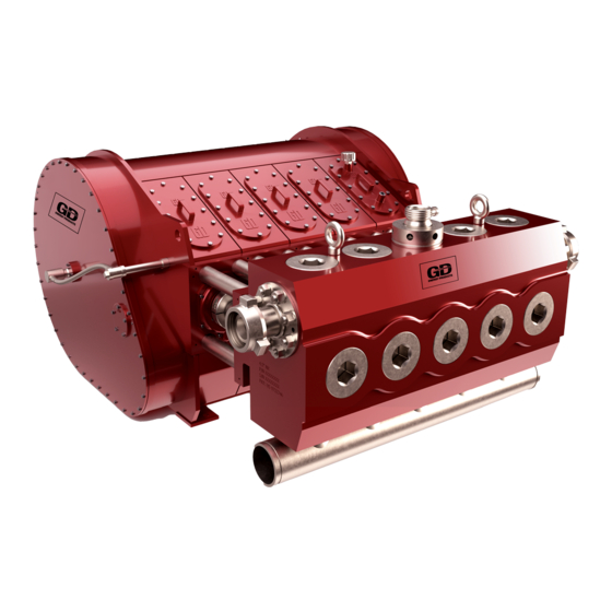
LIST OF ILLUSTRATIONS Figure # Description Page Figure 2-1 GD-2500Q Quintuplex Pump ..............9 Figure 2-2 GD-2500Q Power End Section View ............10 Figure 2-3 GD-2500Q Power End Rear Section View..........11 Figure 2-4 GD-2500Q Gear Reduction Components ..........12 Figure 2-5 GD-2500Q Fluid End ................. -
Page 7: Section 1, Danger Notices
Alterations to the pump, or cracked, damaged or badly worn. application of the pump outside the limits, must not be made without Gardner Denver Wear safety shoes and safety glasses. written approval, together with a new set of... - Page 8 handle to avoid losing control of the Fully engage the wedge to prevent it hammer while swinging and striking. from disengaging violently from the cover as a blow is struck. Carefully swing the hammer to avoid striking themselves, another person and Wipe their hands and the hammer objects other than the targeted lugs or handle and maintain a firm grip on the...
- Page 9 For these smaller loads the lifting devices should be fastened to the lifting attachments normally built into the individual motor, DANGER engine, pump or transmission / torque converter, or their separate support skids. Failure to follow safe and proper When lifting sub-assembled components, for pump, pump package or component example a suction stabilizer attached to lifting or moving procedures can lead...
- Page 10 system, which damage burst Any pipe line used to direct pressurized discharge system components. relief flow to another location, such as a collecting tank, is not blocked. The discharge system is not blocked DANGER and all the discharge line valves are open.
- Page 11 Contact contained by the fluid end, discharge a Gardner Denver service representative for manifold and discharge piping, welding on assistance in selecting the proper packing these components is not recommended. If before beginning operation.
- Page 12 is leaking. Stop the pump immediately if any In addition, on pumping units used where leakage, other than a few drops per minute flammable or explosive vapors could form, of packing seepage, is observed. Keep all all electric motors used as power sources flame, sparks, or hot objects away from any must be of explosion proof construction and part of the pump, suction system, or...
- Page 13 the backward thrust of a hand held device. the work area is checked for hazardous In addition, a safety harness or safety net fumes, has adequate ventilation for engine must be used when working in an area exhaust and sufficient drainage for released where the operator could be injured in a fall.
- Page 14 safety features incorporated their products. After careful study of various manufacturers products, we recommend that only those wands, nozzles, guns, connections and hose, etc., be considered for purchase that you judge to offer the highest quality of design, construction and safety, since these components are among the most critical to the safe operation of high pressure liquid jetting, blasting and cleaning...
-
Page 15: Section 2, Design, Description And Specifications
SECTION 2 DESIGN, DESCRIPTION AND SPECIFICATIONS INTRODUCTION The new Gardner Denver GD-2500Q is a Therefore, in the beginning of this manual the user is introduced to dangers inherent in high horsepower, high rod load multi- the operation of a high-pressure pump. To... -
Page 16: Figure 2-2 Gd-2500Q Power End Section View
Maintenance," addresses the issues of PUMP DESIGN preparing the pump for operation after shipping or storage, the lubrication system The GD-2500Q quintuplex pump uses only design and specifications, the new pump two major assemblies: power end and fluid run-in procedures, and the periodic routine end. -
Page 17: Figure 2-3 Gd-2500Q Power End Rear Section View
FIGURE 2-3: GD-2500Q Power End Rear Section View place and in alignment with the power end by the twenty (20) stay-rods. (See NOTICE FIGURE 2-1). The direction of rotation must be The power end is fully enclosed to contain such that side the power end oil, collecting the oil and... -
Page 18: Figure 2-4 Gd-2500Q Gear Reduction Components
Oil is removed from the power end through POWER END AND GEAR REDUCTION two primary drain connections in the bottom COMPONENTS LUBE SYSTEM (FIGURE 2-2, FIGURE 2-3, and FIGURE 2-4,) of the frame. Oil passages at the forward part of the frame members allow the crosshead cylinders to drain to the power Both the internal gear reduction components end sump. -
Page 19: Figure 2-5 Gd-2500Q Fluid End
FLUID END (FIGURE 2-5) arrange-ment in terms of the valve and spring performance. Improvements in the fluid end life come from increasing fluid This fluid end incorporates the traditional cylinder cross sections in areas of maximum flange-mounted fluid end design, which simplifies installation and removal by simply stresses by reducing internal dimensions removing of the stay-rod nuts. - Page 20 GENERAL SPECIFICATIONS This section presents the pump basic specifications. The first set of specifications deals with the pump's power, rod load, plunger stroke, and overall dimensions. The other table presents allowable pressures and flows for various pump speeds along with data on power requirements. GD-2500Q PERFORMANCE RATING Rated Brake Horsepower 2500bhp...
-
Page 21: Section 3, Preparation, Operation And Maintenance
SECTION 3 PREPARATION, OPERATION AND MAINTENANCE Coat the gear reducer input shaft and DANGER all exposed bare metal with a heavy rust preventive. Read and understand clearly all Plug drain holes at the bottom of the safety rules and precautions before pump frame, located underneath the attempting to operate the pump. - Page 22 When connecting the suction line to the The oil flow velocity through the suc- suction manifold, provide support to the tion piping should not exceed 2 ft/sec. suction line independent of the pump suction manifold. Fluid adds weight to At maximum operating speed the the suction line.
-
Page 23: Figure 3-1 Lubricant Recommendations
FIGURE 3-1 Lubricant Recommendations PLUNGER / PACKING LUBRICATION The first startup and several hours of the pump run-in are performed at the factory during the acceptance tests as a part of The fluid end plungers are lubricated from a separate lubrication pump through the quality assurance procedure. - Page 24 Fill the packing lube reservoir with 14. If the quintuplex pump is equipped with proper oil. "Plunger/Packing a transmission, run the pump for 30 min in each gear in the higher gear Lubrication Recommendation Chart," ranges pulling full horsepower in each page 20.
- Page 25 tasks to be performed by the user after the pump has gone through 100 hours of wear- Check all fluid end expendables such in period. For the tasks performed during the as valves, packings, and valve seats wear-in period, see "Startup and New Pump and replace them as necessary.
- Page 26 PLUNGER PACKING LUBRICATION RECOMMENDATION CHART ROCK DRILL LUBRICANTS - NORMAL CONDITIONS Source Type Pour Point Maximum Amoco Amoco Rock Drill Oil - Light -20 F Amoco Rock Drill Oil - Medium Arco Air Drill #147 Arco Trueslide #150 15 F Chevron Oil U.S.A.
-
Page 27: Section 4, Service Procedures
SECTION 4 SERVICE PROCEDURES This section describes various assembly FLUID END SERVICE and disassembly procedures necessary for pump servicing or parts replacement. The This discussion starts with the description of General Requirements and Safety Rules steps necessary for removal and installation section is a reminder for the maintenance of the fluid cylinder assembly and proceeds personnel of the critical importance of safety... -
Page 28: Figure 4-1 Gd-2500Q Fluid End Tightening Sequence
Plunger and Packing Replacement NOTICE This service procedure can be performed with the fluid cylinder in place on the pump, While the stay rods are available to and consists of the following steps: inspect, check loose stay rods and cracked threads in all stay rods. The Remove the suction cover retainer nut connection between the power end with the appropriate male hex wrench. - Page 29 11. Install and hand tighten the packing nut to align the packing in the bore. WARNING 12. Loosen the packing nut to allow for installation of the plunger. Never try to remove or cut a 13. Insert the plunger through the suction valve seat with a torch.
-
Page 30: Figure 4-3 Fluid End Valve Stop
These tools are available from Gardner Denver. Oil Stop Head Seal Retainer and Gear Covers (FIGURE 2-2 and FIGURE 2-3) Clean the valve seat deck thoroughly. -
Page 31: Figure 4-4 Gd-2500Q Crosshead Assembly
Remove the main rear inspection cover Crosshead Assembly (FIGURE 4-4) from power frame. (Inspect Remove the fluid end following the gaskets) procedure described in "Fluid End Remove the extension rods from the Removal and Installation, page 21. front. Remove the oil stop head seal retainer and off-drive gear cover following the Using the correct puller, remove two keeper... - Page 32 Local done either by Gardner Denver or a heat may (approx. 200 F) may be qualified machine shop. required to remove the bearing from the pinion.
- Page 33 loosen the bearing race from the frame 2. Heat the bearings uniformly, and install bore. DO NOT OVERHEAT AND the third bearing from the top first, then DAMAGE THE BEARING!! In the the second bearing from the top, and event the outer race can not be pulled finally the outside bearing.
- Page 34 WARNING When reassembling the crankshaft assembly, make sure to follow these steps: Pack the outer bearing races in dry ice before assembling in the frame. Heat the inner bearing races before installing on crankshaft. (250 F max. oven or oil bath). Braze the retaining rings in the frame after installing the outer main bearing races.
-
Page 35: Section 5, Trouble-Shooting
SECTION 5 TROUBLE-SHOOTING PROBLEM POSSIBLE CAUSE SUGGESTED ACTION Pump Overloads Driver. 1. Excessive pump speed 1. Reduce pump speed and/or and/or discharge pressure. pressure. 2. Blockage or closed 2. Clean or open valve. valve in discharge line. 3. Incorrect plunger size. 3. - Page 36 PROBLEM POSSIBLE CAUSE SUGGESTED ACTION Cavitation, Fluid Knock 1. Improper suction system 1. See recommended system or Hammer. layout. layout in manual. 2. Low suction pressure. 2. See Low Suction Pressure problem. 3. Suction stabilizer and 3. Install suction stabilizer pulsation damper not used.
- Page 37 PROBLEM POSSIBLE CAUSE SUGGESTED ACTION Knock In Power End. 1. Improper main bearing 1. Check and adjust clearance. clearances. 2. Incorrect pump rotation. 2. Reverse rotation. 3. Loose plunger coupling. 3. Check and tighten. Replace if damaged. 4. Loose bearing housings/ 4.
- Page 38 PROBLEM POSSIBLE CAUSE SUGGESTED ACTION Oil Seal Leakage. 1. Worn sealing lip. 1. Replace seal. 2. Damaged sealing lip. 2. Replace seal. 3. Outside diameter not seated. 3. Clean and polish bore of oil seal housing. 4. Shaft rough at seal lip. 4.
- Page 39 PROBLEM POSSIBLE CAUSE SUGGESTED ACTION Short Plunger/Packing Life. 1. Abrasives in pumped fluid. 1. Consult Gardner Denver Customer Service for plunger/ packing recommendation. Filter pumped fluid. 2. Excessive plunger/packing 2. Lubricate with rock drill oil. friction. Do not overtighten adjust- able packing.
- Page 40 4. Treat fluid or use corrosion fluid. resistant studs. 5. Studs damaged before 5. Check condition before installation. installation, and replace if necessary. 6. Low strength studs. 6. Use Gardner Denver studs. 300FWF996 Page 34 HALLIBURTON EXHIBIT 1013, Page 40...
-
Page 41: Section 6, Rebuilding Data, Recommended Running Clearances And Torques
SECTION 6 REBUILDING DATA, RECOMMENDED RUNNING CLEARANCES AND TORQUES REBUILDING DATA FOR GD-2500Q PUMP (in.) PUMP STROKE 8 Inches Crankshaft Throw Diameter..........7.4995 / 7.4985 Crankshaft Shaft Diameter at Main Bearing ......16.002 / 16.001 Distance Between Main Bearing Centers......10.00 Bore in Frame for (4) Inner Main Bearings ...... - Page 42 GD-2500Q QUINTUPLEX TORQUES FOOT POUNDS DESCRIPTION FASTENER WITH LOCTITE WITH ANTISEIZE Plunger Clamp Bolts .1/2 -13 Pinion Bearing Housing ........3/4 -10 Conn. Rod Fasteners........... 3/4 -10 Intermediate Rod to Crosshead......3/4 -10 Fluid End to Suction Manifold ......7/8 - 9 Discharge Flange to Fluid Cylinder Nuts .....
-
Page 43: Warranty
BE-13 R 02/2003, Copyright © 2003 Gardner Denver, Inc. GENERAL PROVISIONS AND LIMITATIONS Gardner Denver (the "Company") warrants to each original retail purchaser ("Purchaser") of its new products, assemblies or parts from the Company or its authorized distributors that such products are, at the time of delivery to the Purchaser, made with good material and workmanship. - Page 44 At the expense of the Purchaser, any product properly preserved must be inspected by an authorized agent of the Company, prior to the Company, granting any extended warranty beyond that stated in this warranty. LABOR TRANSPORTATION AND INSPECTION The Company will provide labor, by Company representative or authorized service personnel, for repair or replacement of any product or part thereof which in the Company's judgment is proved not to be as warranted.
- Page 45 Facsimile or letter to: Warranty Department c/o Gardner Denver Petroleum Pumps 4747 South 83 East Avenue Tulsa, Oklahoma 74145 Email: CCR.QAR@gardnerdenver.com Facsimile: (918) 664-6225 BE-13 R 02/2003, Copyright © 2003 Gardner Denver, Inc. 300FWF996 Page 39 HALLIBURTON EXHIBIT 1013, Page 45...
- Page 46 Gardner Denver Inc. 4747 South 83 East Avenue, Tulsa, OK 74145 PH: (918) 664-1151, (800) 637-8099 FAX: (918) 664-6225 www.gardnerdenver.com Specifications subject to change without notice. Copyright © 2001 Gardner Denver, Inc. Litho in U.S.A. HALLIBURTON EXHIBIT 1013, Page 46...
Need help?
Do you have a question about the GD-2500Q QUINTUPLEX and is the answer not in the manual?
Questions and answers