
Subscribe to Our Youtube Channel
Related Manuals for Gardner Denver HD-2250


Summary of Contents for Gardner Denver HD-2250
- Page 1 GARDNER DENVER ® 300THD996 Revision D April 2011 HD-2250 TRIPLEX PUMP OPERATING AND SERVICE MANUAL ECN 1058968...
-
Page 2: Instructions For Ordering Repair Parts
Reliability in materials and quality assurance is incorporated in our genuine replacement parts. Your authorized Gardner Denver Sales Office offers all the backup you’ll need. The Fort Worth Manufacturing Facility maintains a large inventory of genuine parts. -
Page 3: Foreword
FOREWORD Gardner Denver® pumps are the result of advanced engineering and skilled manufacturing. To be assured of receiving maximum service from this pump the owner must exercise care in its operation and maintenance. This book is written to give the operator and maintenance personnel essential information for day-to-day operation, maintenance and adjustment. -
Page 4: Table Of Contents
TABLE OF CONTENTS Maintain Pump Reliability and Performance with Genuine Gardner Denver Parts and Support Services ......................i Instructions For Ordering Repair Parts .................. i Foreword..........................ii Index............................. iv List of Illustrations ......................... v Section 1, Danger Notices..................... 1 Section 2, Design, Description and Specifications ..............9 Section 3, Preparation, Operation and Maintenance.............. -
Page 5: Index
Valve Seat Pulling, Danger Notice ....2 Lube System Pump ........15 Warranty ............. 35 Monthly Routine Maintenance Schedule ..18 Wedge Puller, Danger Notice ......2 Performance Rating, HD-2250....13 Periodic Routing Maintenance Schedule..18 Plunger/Packing Lubrication ....... 16 Plunger Packing Lubrication Recommendation Chart ...... 19 Plungers and Packing Replacement ... -
Page 6: List Of Illustrations
LIST OF ILLUSTRATIONS Figure # Description Page Figure 2-1 HD-2250 Pump ..................9 Figure 2-2 HD-2250 Power End Section A-A............10 Figure 2-3 HD-2250 Power End Section B-B............11 Figure 2-4 Fluid End ....................12 Figure 3-1 Power End Lubricant Recommendations..........16 Figure 4-1 Fluid End, Stay Rods, and Heavy Hex Nuts........... -
Page 7: Section 1, Danger Notices
Replace any of these parts which are application of the pump outside the limits, cracked, damaged or badly worn. must not be made without Gardner Denver written approval, together with a new set of Wear safety shoes and safety glasses. - Page 8 Wipe their hands and the hammer • handle and maintain a firm grip on the Check to insure they have safe footing. • handle to avoid losing control of the hammer while swinging and striking. Fully engage the wedge to prevent it •...
- Page 9 aware of the use, capability, and condition attachments normally built into the package of both the equipment being moved and the unit support skid. Packages too large to lift equipment being used to move it. as fully assembled should be separated into smaller loads.
- Page 10 The pressure relief valve is in good • operating condition and has been set to Operating a pump against a blocked or the proper relief pressure. restricted discharge line produce excessive pressures in the entire discharge Any pipe line used to direct pressurized system, which damage...
- Page 11 Proper stuffing box packing selection is important for safe pump operation. Contact Due to the high working pressures contained a Gardner Denver service representative for by the fluid end, discharge manifold and assistance in selecting the proper packing discharge...
- Page 12 the presence of flammable or explosive equipment damage due to explosion, vapors. Do not begin operation and stop fire, extreme cold or chemical attack. ongoing operation if flammable or explosive vapors are detected. Hot surfaces, sparks, electric current or engine exhaust could Never operate a pump which is pumping ignite flammable or explosive vapors.
- Page 13 Pressure or flow directing devices often clothing including, but not limited to, a hard receive pressurized flow through flexible hat with full face visor, heavy duty rain coat hoses, which can burst if they are kinked, and pants, boots with nonskid sole and cut, abraded otherwise...
- Page 14 care. Protect them from damage by people, objects and vehicles. Never lay them in dirt, mud, ice or other loose material which could plug the fluid opening or interfere with their operation. Never use the wand, nozzle, gun, etc. to pry loose material off items being cleaned.
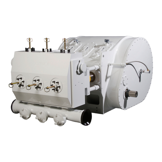
- Page 15 FIGURE 2-1 – HD-2250 PUMP Page 9...
-
Page 16: Section 2, Design, Description And Specifications
The Issue of personnel safety is the most important topic covered in this manual. Therefore, in the beginning of this manual The Gardner Denver HD-2250 is a multi- the user is introduced to dangers inherent in purpose pump for various applications such the operation of a high pressure pump. - Page 17 The direction of rotation must be such that top side of the crankshaft is moving toward the fluid end. FIGURE 2-2 - HD-2250 POWER END CROSS SECTION Page 10...
-
Page 18: Figure 2-1 Hd-2250 Pump
This one piece design was first consuming, inexact, manual timing of these developed by Gardner Denver. It features a gears. hardened and ground thrust area for extended wear capabilities. -
Page 19: Figure 2-2 Hd-2250 Power End Section A-A
improved resistance to fatigue POWER END INTERNAL LUBE SYSTEM cracking. (FIGURE 2-2, page 10, and FIGURE 2-3, page 11) Extreme pressure autofrettage for long cylinder life and resistance to cracking There is a single inlet for the lube oil, at the bore intersection areas. coming from the lube oil pump. -
Page 20: Figure 2-3 Hd-2250 Power End Section B-B
9170 Brake Horsepower* 1600 2250 2250 2250 * Based on 90% Mechanical Efficiency and 100% Volumetric Efficiency. HD-2250 5,000 PSI DRILLING SERVICE PERFORMANCE RATING – U.S. (1,000 hrs per year) Plunger Size Gallons Per 50 RPM 100 RPM 150 RPM... -
Page 21: Section 3, Preparation, Operation And Maintenance
SECTION 3 PREPARATION, OPERATION AND MAINTENANCE Coat the gear reducer input shaft and all exposed bare metal with a heavy DANGER rust preventive. Plug drain holes at the bottom of the Read and understand clearly all pump frame, at the rear of the pump, safety rules and precautions before and the gear reducer drain. - Page 22 other special fluids and propping agents. To The suction strainer should be sized for reduce shock and cavitation, which can oil flow three (3) times larger than the cause severe damage, a suction dampener actual flow passing through should be used. strainer.
- Page 23 FIGURE 3-1 Lubricant Recommendations PLUNGER / PACKING LUBRICATION The first startup is performed at the factory during the acceptance tests as a part of The fluid end plungers are lubricated from a quality assurance procedure. However, the separate lubrication pump through the new pump break-in period process may stuffing box.
- Page 24 Fill the plunger reservoir with proper oil. See “Plunger/Packing Lubrication During the operation, observe the oil Recommendations” on Page 19. pressure and temperature, and inlet suction vacuum gage reading, and Remove all inspection covers on the entire system for proper operation. top of the pump frame.
-
Page 25: Figure 3-1 Power End Lubricant Recommendations
packing nut is tightened sufficiently into PERIODIC ROUTINE MAINTENACE fluid cylinder. Recheck tightness after SCHEDULE extended continuous operation. Performance periodic routine maintenance tasks, described this Monthly (100 hour) Routine Maintenance section, will ensure long, economical, and trouble free operation of this pump. It is Tasks highly recommended that the customer set Clean the strainer and replace the oil... - Page 26 PLUNGER PACKING LUBRICATION RECOMMENDATION CHART ROCK DRILL LUBRICANTS - NORMAL CONDITIONS Source Type Pour Point Maximum Amoco Amoco Rock Drill Oil - Light -20°F Amoco Rock Drill Oil - Medium 0°F Arco Air Drill #147 0°F Arco Trueslide #150 15°F Chevron Oil U.S.A.
-
Page 27: Section 4, Service Procedures
SECTION 4 SERVICE PROCEDURES This section describes various assembly and disassembly procedures necessary for FLUID END SERVICE pump servicing or parts replacement. The General Requirements and Safety Rules This discussion starts with the description of section is a reminder for the maintenance steps necessary for removal and installation personnel of the critical importance of safety of the fluid cylinder assembly and proceeds... - Page 28 1. Apply a light coating of grease to the valve cover seal(s), retainer threads, and retainer face before installation. 2. Install the valve cover and retainer into the fluid cylinder. FIGURE 4-1 HD-2250 Fluid End, Stay Rods and Hvy. Hex. Nuts. Page 21...
- Page 29 3. Seat the valve cover completely against Retainer Thread Movement the shoulder of the fluid cylinder by Diameter inserting “Hex Retainer Tool” 4” to 5 -1/4” 7/16” through the retainer until it contacts the valve cover and tapping the tool over 5 -1/2”...
-
Page 30: Figure 4-1 Fluid End, Stay Rods, And Heavy Hex Nuts
Installation: Plunger and Packing Replacement This service procedure can be performed with the fluid cylinder in place on the pump, 1. Loosen the jackbolts so that they do not and consists of the following steps: extend from the mating face of the retainer. -
Page 31: Figure 4-3 Valve Cage Spring Retainer
These tools are Never try to remove or cut a valve available from Gardner Denver. seat with a torch. Severe damage to the fluid end may occur. Clean the valve seat deck thoroughly. - Page 32 10. Bump the seat into the taper 2-3 times Remove the Oil Stop Head retainer with a heavy bar to make the fit tight. cap screws and remove the Head. 11. Reinstall the valve spring and suction Remove roto-seals and oil hoses from valve spring retainer.
-
Page 33: Figure 4-5 Crosshead Assembly
FIGURE 4-5 Crosshead Assembly 11. Remove fasteners from done either by Gardner Denver or a crosshead thrust-bearing retainer. qualified machine shop. Remove the retainer to access the The stay rods are threaded into the thrust bearing. power frame. They can be easily replaced by unscrewing and re-torquing 12. - Page 34 Cut the safety wire (if used) and Install the “special” crankshaft lifting remove the four (4) screws. tool, and balance the crank with an 7. Remove the set screws on the square overhead lift. keys, pull keys with a puller. 10.
- Page 35 Install the outer races and retainer rings in the power frame. A light uniform pressure is required to install WARNING the race. The retainer rings are secured in grooves by installing locks. When reassembling crankshaft The crankshaft can be installed through assembly, make sure to follow these either end of the power end.
-
Page 36: Section 5, Trouble-Shooting
SECTION 5 TROUBLE-SHOOTING PROBLEM POSSIBLE CAUSE SUGGESTED ACTION Pump Overloads Driver. 1. Excessive pump speed 1. Reduce pump speed and/or and/or discharge pressure. pressure. 2. Blockage or closed 2. Clean or open valve. valve in discharge line. 3. Incorrect plunger size. 3. - Page 37 PROBLEM POSSIBLE CAUSE SUGGESTED ACTION Cavitation, Fluid Knock 1. Improper suction system 1. See recommended system or Hammer. layout. layout in manual. 2. Low suction pressure. 2. See Low Suction Pressure problem. 3. Suction stabilizer and 3. Install suction stabilizer pulsation damper not used.
- Page 38 PROBLEM POSSIBLE CAUSE SUGGESTED ACTION Knock In Power End. 1. Improper main bearing 1. Check and adjust clearance. clearances. 2. Incorrect pump rotation. 2. Reverse rotation. 3. Loose plunger coupling. 3. Check and tighten. Replace if damaged. 4. Loose bearing housings/ 4.
- Page 39 PROBLEM POSSIBLE CAUSE SUGGESTED ACTION Oil Seal Leakage. 1. Worn sealing lip. 1. Replace seal. 2. Damaged sealing lip. 2. Replace seal. 3. Outside diameter not seated. 3. Clean and polish bore of oil seal housing. 4. Shaft rough at seal lip. 4.
- Page 40 PROBLEM POSSIBLE CAUSE SUGGESTED ACTION Short Plunger/Packing Life. 1. Abrasives in pumped fluid. 1. Consult Gardner Denver Customer Service for plunger packing recommendation. Filter pumped fluid. 2. Excessive plunger/packing 2. Lubricate with rock drill oil. friction. Do not overtighten adjust- able packing.
- Page 41 4. Corrosive attack by pumped 4. Treat fluid or use corrosion fluid. resistant studs. 5. Studs damaged before 5. Check condition before installation. installation, and replace if necessary. 6. Low strength studs. 6. Use Gardner Denver studs. Page 32...
- Page 42 SECTION 6 REBUILDING DATA, RUNNING CLEARANCES AND TORQUES REBUILDING DATA FOR HD-2250 PUMP (in.) PUMP STROKE 8 Inches Crankshaft Throw Diameter..........7.251” / 7.249” Crankshaft Shaft Diameter at Main Bearing ...... 16.002” / 16.001” Distance Between Main Bearing Centers......12.00”...
- Page 43 RECOMMENDED TORQUES FOR HD-2250 PUMP MAINTENANCE TORQUES FOOT POUNDS DESCRIPTION FASTENER WITH LOCTITE WITH ANTISEIZE Gear Covers, Misc..........3/8”-16 Main Bearing retainer plate screws (Gr. 8)………1/2”-13 Plunger Clamp Bolts……………………………….. 1/2”-13 Pinion Bearing Housing........3/4”-10 Extension Rod to Crosshead ......3-1/4”-8 1200 Conn Rod to Bearing Housing, Lock Nuts………..
-
Page 44: Warranty
BE-13 R 02/2003, Copyright © 2003 Gardner Denver, Inc. GENERAL PROVISIONS AND LIMITATIONS Gardner Denver (the "Company") warrants to each original retail purchaser ("Purchaser") of its new products, assemblies or parts from the Company or its authorized distributors that such products are, at the time of delivery to the Purchaser, made with good material and workmanship. - Page 45 Rotate pump every 30 days to insure bearings are oiled. At the expense of the Purchaser, any product properly preserved must be inspected by an authorized agent of the Company, prior to the Company, granting any extended warranty beyond that stated in this warranty. LABOR TRANSPORTATION AND INSPECTION The Company will provide labor, by Company representative or authorized service personnel, for repair or replacement of any product or part thereof which in the Company's judgment is proved not to...
- Page 46 Company prior to shipment. All requests for product return shall be submitted by email. Facsimile or letter to: Warranty Department c/o Gardner Denver Petroleum Pumps 4747 South 83 East Avenue Tulsa, Oklahoma 74145 Email: CCR.QAR@gardnerdenver.com Facsimile: (918) 664-6225 BE-13 R 02/2003, Copyright © 2003 Gardner Denver, Inc. Page 37...
- Page 47 For additional information contact your local representative or Gardner Denver Inc. 4747 South 83 East Avenue, Tulsa, OK 74145 PH: (918) 664-1151, (800) 637-8099 FAX: (918) 664-6225 www.gardnerdenver.com Specifications subject to change without notice. Copyright © 2001 Gardner Denver, Inc. Litho in U.S.A.
Need help?
Do you have a question about the HD-2250 and is the answer not in the manual?
Questions and answers