Moog Memorymoog 345 Owner's Manual
Hide thumbs
Also See for Memorymoog 345:
- Owner's and service manual (106 pages) ,
- Technical service information (68 pages) ,
- Owner's and service manual (106 pages)
Table of Contents
Advertisement
MANUAL NO. 997-045924-001
OWNERS and
SERVICE MANUAL
for
MEMORYMOOG
®
MODEL 345
This binder contains the complete owners and technical manuals for the Memorymoog.
As updates and improvements are made in the instrument, they will be described in the
Addenda section in the back of the manual.
COPYRIGHT - 1982
MOOG MUSIC INC.
Advertisement
Table of Contents

Subscribe to Our Youtube Channel
Related Manuals for Moog Memorymoog 345


Summary of Contents for Moog Memorymoog 345
- Page 1 This binder contains the complete owners and technical manuals for the Memorymoog. As updates and improvements are made in the instrument, they will be described in the Addenda section in the back of the manual. COPYRIGHT - 1982 MOOG MUSIC INC.
-
Page 2: Table Of Contents
MEMORYMOOG OWNERS MANUAL CONTENTS INTRODUCTION ......................1 SECTION I Setting Up ........................2 Calling Up Programs ....................... 3 Editing A Sound ......................3 Calling Up and Stepping Through Program Sequences ..........4 SECTION II Keyboard/Performance Controls ..................5 Left-Hand Controllers ...................... 7 System Controller ...................... - Page 3 CONTENTS (Continued) Frequency Controls ......................29 Osc 3 as a Low-Frequency Oscillator ................30 The Noise Source ......................30 The Mixer ........................30 The Voltage-Controlled Filter ..................31 Emphasis ........................31 KB Track ........................32 Contour Amount ......................33 The Contour Generators ....................33 Contour Mode Controls ....................
-
Page 4: Introduction
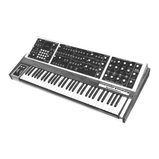
INTRODUCTION The Memorymoog is a voice-assignment polyphonic synthesizer with the ability to store up to 100 patches in computer memory. It has six independent voices, each containing three voltage-con- trolled oscillators, a voltage-controlled 24dB/octave lowpass filter, two ADSR contour generators, and extensive modulation facilities. -
Page 5: Section I
Turn the output volume of both the Memorymoog and the amp down to zero. Turn the Memory- moog on and then turn the amp on. Bring the volume of the amp up to where you're used to setting it. While holding down a note, bring the MASTER VOLUME control (at the upper right corner) up... -
Page 6: Calling Up Programs
After you've turned the instrument on, let it warm up for about 10 SYSTEM CONTROLLER minutes to allow the oscillators to stabilize. Then hit the AUTO TUNE control in the upper left-hand corner. This will tune the Memorymoog's 18 oscillators. Notice that the SYSTEM CONTROLLER's Alphanu- meric Display reads "6 TUNED"... -
Page 7: Calling Up And Stepping Through Program Sequences
CALLING UP AND STEPPING THROUGH PROGRAM SEQUENCES To get into the PROGRAM SEQUENCE MODE hit PREFIX letter D, followed by any number from 0 to 9, followed by ENTER. This gets you to one of the 10 PROGRAM SEQUENCES. What will appear in the Alphanumeric Display looks like this: SYSTEM CONTROLLER PROGRAM... -
Page 8: Keyboard/Performance Controls
SECTION II This section of the Memorymoog manual is designed to answer questions about the function of each control on the front and back panels of the instrument. It's a quick reference guide; more detailed explanations will be found in the next portion of the manual. 1.0 KEYBOARD/PERFORMANCE CONTROLS. - Page 9 1.7 KB MODE. KEYBOARD MODE affects the priority of the keyboard when it's in both mono and polyphonic AUTO TUNE modes. In mono mode, the SYSTEM CONTROL- TUNE LER (3.0) Alphanumeric Display shows either "MONO 1, 2 or 3," depending on the mono mode MONO KB OUT MULTIPLE...
-
Page 10: Left-Hand Controllers
2.0 LEFT-HAND CONTROLLERS. 2.1 OCTAVE SWITCHES. These are not programmable. They raise or lower the pitch of all oscillators by one octave. OCTAVE 2.2 PITCH WHEEL. Lets you bend the pitch of what's played on the keyboard by an amount determined by the PITCH BEND AMOUNT con- PITCH trol (1.11). - Page 11 3.3 NUMERIC KEYBOARD. This calculator-type keyboard is used for calling up programs and other control functions. You do this by hitting one or two numbers (from 0 to 99) and then pressing the ENTER button. 3.4 RECORD INTERLOCK. This switch is used to temporarily lock the front panel settings in memory. By hitting LOCK, the Alphanumeric Display (3.2) will read "LOCK,"...
- Page 12 PREFIX C5 tunes all oscillators to unison, regardless of front panel settings. PREFIXES C6 and C7 are electronic tuning aids for service technicians. PREFIX C8 displays current memory status, ENABLED or DISABLED in the Alphanumeric Dis- play (3.2). The unit powers up with the memory disabled so that you can't accidentally record a patch and you can't use the cassette interface functions of PREFIXES C1, 2, and 3.
-
Page 13: Footpedals
4.0 FOOTPEDALS. 4.1 AMOUNT 1, PITCH, VOLUME, FILTER. The AMOUNT knob controls the overall range of footpedal num- FOOT PEDALS AMOUNT 1 ber 1 which can be routed to control the pitch of all the oscillators, the volume, and the filter's cutoff frequency. Functions are pro- grammable. - Page 14 5.4 VOICE MODULATION. The source of this modulation is selectable from either the filter's contour generator or the third os- cillator. These affect each voice independently. Voice Modulation is independent of the LFO Modu- lation (5.0). 5.5 OSC 3. Controls the amount of modulation from oscil- lator 3.
-
Page 15: Oscillators
6.0 OSCILLATORS. 6.5 FREQUENCY (oscillator 2). A dual concentric pot which lets you tune the second oscillator ± a minor sixth. The outer 6.1 OCTAVE (oscillators 1, 2, 3). 16', 8', 4', and 2' octave settings for each os- ring is for coarse control and the inner ring is cillator are available via these switches. -
Page 16: Mixer
At a setting of 10 you will hear some intermodulation distortion. LEVEL 8.0 VOLTAGE CONTROLLED FILTER. The Voltage Controlled Filter is the patented Moog 24db/octave low- pass filter. LEVEL 8.1 KB TRACK. Varies the amount of voltage from the keyboard that controls the filter cutoff frequency. -
Page 17: Voltage Controlled Amplifier
9.0 VOLTAGE CONTROLLED AMPLIFIER. An ADSR contour generator controls the VCA. VOLTAGE CONTROLLED FILTER 9.1 ATTACK. KB TRACK Same as section 8.6. 9.2 DECAY. CUTOFF EMPHASIS CONTOUR AMOUNT Same as section 8.7. 9.3 SUSTAIN. Same as section 8.8. 1 MSEC 10 SEC 2 MSEC 20 SEC... -
Page 18: Outputs
11.0 OUTPUTS. OUTPUTS 11.1 MASTER VOLUME. A non-programmable volume control. 11.2 PROGRAMMABLE VOLUME. MASTER VOLUME Used for matching volume levels between programs. PROGRAMMABLE 11.3 HEADPHONE VOLUME. A non-programmable volume control that's independent of the MASTER VOLUME control (11.1 ). It adjusts the level VOLUME of the stereo headphone output. -
Page 19: External Synthesizer Out
14.0 EXTERNAL SYNTHESIZER OUT. 15.2 HOLD. A switch input for turning the HOLD function (1.8) on and off. 14.1 CONTROL VOLT 1 VOLT/OCT. A 1 volt-per-octave (± 10%) output for con- trolling an external synthesizer or synthesizer 15.3 PROGRAM ADVANCE. accessory. -
Page 20: The System Controller
SECTION III THE SYSTEM CONTROLLER The SYSTEM CONTROLLER is the heart of the SYSTEM CONTROLLER Memorymoog. Of all the front panel controls, you'll find PROGRAM yourself using the SYSTEM CONTROLLER most fre- DISPLAY quently. It is used to store and recall patches, set up key- PROGRAM board modes, set up arpeggiation modes, control program sequencing, access the cassette interface, and many other... -
Page 21: Recording Programs
RECORDING PROGRAMS In order to record your own patches into the program memory you have to ENABLE the record function. To do this, press PREFIX BUTTON C (3.6), hit 8, and hit ENTER. This will display the status of the instrument. The Alphanumeric Display will read "DISABLED" or "ENABLED." Now you must enter a four-digit security code (when each instrument is shipped, the code is 0000). - Page 22 To edit or change any preset program, change any of the parameters by moving a pot or pushing a switch. When you hit a switch, you'll notice the Alphanumeric Display will read "EDIT" to tell you you've changed a parameter of the program. If you turn a pot, you'll see six numbers appear in the Alphanumeric Display.
-
Page 23: Program Sequences
GRAM SEQUENCE. You can use the A and B PREFIX switches on the Numeric Keyboard (see di- agram above) or you can use ADVANCE and BACKSTEP footswitches (not supplied with the in- strument, but available as Moog accessory number 1122). The A PREFIX switch advances (steps forward into) the PROGRAM SEQUENCE, while the B PREFIX switch backsteps through the PROGRAM SEQUENCE. - Page 24 HIT D HIT D HIT A NUMBER FROM 0 TO 9 HIT ENTER = LOADING MODE HIT # HIT ENTER HIT A HIT ENTER = LOAD A PROGRAM FORWARD INTO PROGRAM SEQUENCE HIT # HIT ENTER HIT B HIT ENTER = LOAD A PROGRAM BACKWARD INTO PROGRAM SEQUENCE Should you decide that you want to replace a program in the SEQUENCE, you can step through the chain to the program you want to replace and repeat the steps above for recording a program into the SEQUENCE.
-
Page 25: The Cassette Interface
THE CASSETTE INTERFACE This is used to store information from the memory onto cassette tapes, expanding your library of patches beyond the 100 that the Memorymoog will hold. To access the interface, it's necessary to connect the cassette properly. SIGNAL IN (MIC OR AUX) SIGNAL OUT (EAR PHONE) MOTOR START/STOP .140"... -
Page 26: The Keyboard
Hit the highest note on the Memory- moog and adjust the SCALE trimmer until it's in tune with the external synth. You may have to go back and forth between the RANGE and SCALE controls a bit before the instruments are exactly in tune with each other. -
Page 27: Modulation
Next, hit KB MODE, hit 2, hit ENTER. That will put the keyboard in POLYPHONIC MODE 2, CYCLIC WITH MEMORY. Now when you repeat the same chord over and over again, you should only hear glide the first time you strike the chord. The second and each consecutive time you strike that chord, the computer memory remembers that the voices have been assigned to the various pitches you are playing. -
Page 28: Changing The Number Of Voices The Keyboard Controls In Mono Mode
CHANGING THE NUMBER OF VOICES THE KEYBOARD CONTROLS IN MONO MODE When you put the keyboard into its MONOPHONIC MODE by pressing the MONO switch (1.3), the keyboard will play only one note at a time. It will control from I to 18 oscillators, depend- ing on how many voice cards are being controlled. -
Page 29: The Hold Function
With the SINGLE/MULTIPLE TRIGGER switch (1.4) on, the keyboard will put out a new trig- ger for every note played, regardless of whether or not any other note is still being held down. You'll notice that if you try to play legato, the keyboard will still put out new triggers, foiling your every attempt to avoid them. -
Page 30: The Oscillators
THE OSCILLATORS The 18 voltage-controlled oscillators of the Memorymoog produce the pitches you hear when you play the keyboard. The control voltage output from the keyboard determines the oscillators' pitch. Pitch is supplied by an oscillator when its waveform, a periodic fluctuation of voltage, is translated by a speaker cone into a fluctuation of air, which we perceive as pitch.
Need help?
Do you have a question about the Memorymoog 345 and is the answer not in the manual?
Questions and answers