Fisher & Paykel GC912 series Service Manual
Gc912 series; gc913 series gas cooktops
Hide thumbs
Also See for GC912 series:
- User manual (52 pages) ,
- Installation instructions manual (33 pages) ,
- User manual (52 pages)
Table of Contents
Advertisement
Quick Links
Advertisement
Table of Contents

Subscribe to Our Youtube Channel
Related Manuals for Fisher & Paykel GC912 series


Summary of Contents for Fisher & Paykel GC912 series
-
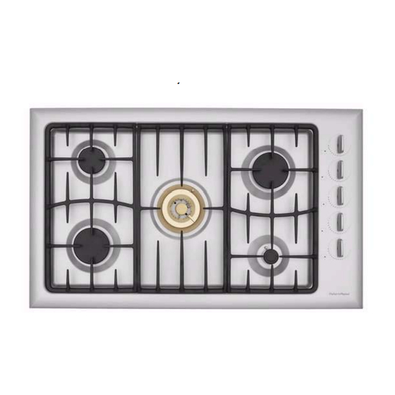
Page 1: Gas Cooktops
Gas Cooktops USA, Canada Models GC912 and GC913 series 599328A... - Page 3 599328A April 2006 Manual 599328A Reprint: April 2006 The specifications and servicing procedures outlined in this manual are subject to change without notice. The latest version is indicated by the reprint date and letter and replaces any earlier editions.
-
Page 4: Table Of Contents
599328A Contents Models covered by this manual ........................5 Service assistance............................5 Service requirements ..........................6 1.1 H ..........................6 EALTH AND AFETY 1.2 G ..........................6 ENERAL WARNING Specifications............................7 2.1 P ..........................7 RODUCT OVERVIEW 2.2 M ............................7 ODEL NUMBER 2.3 S ............................8 ERIAL NUMBER 2.4 E .............................8 LECTRICAL... -
Page 5: Models Covered By This Manual
599328A Models covered by this manual MODEL PRODUCT CODE GC912 88441 GC912M 88442 GC913 88452-A Service assistance Fisher & Paykel Appliances inc. 5900 Skylab Road Huntington Beach CA 92647 Tel: 1-888-936-7872 Fax: 949-790-8913 Email: Customer.Care@fisherpaykel.com... -
Page 6: Service Requirements
599328A Service requirements 1.1 Health and Safety When servicing the cooktop, health and safety issues must be considered at all times. Specific safety issues are listed below with their appropriate icon. They are illustrated in the service procedures to remind service people of the issues. Electrical safety. -
Page 7: Specifications
599328A Specifications 2.1 Product overview Model GC912 GC912M GC913 Supply voltage 110/120 110/120 110/120 Flame failure auto reignition Brushed stainless steel panels Iridium stainless steel panels Wok burner 14000BTU/h 20000BTU/h 20000BTU/h Indicator neons, innovalves 2.2 Model number Note: A model and serial number label is located on the underside of the cooktop and on the cover of the use and care guide supplied with the product. -
Page 8: Serial Number
599328A 2.3 Serial number The serial number consists of three letters and six digits and contains the information shown in the following example: B R M 123456 Sequential serial number Manufacturing plant code FISHERPAYKUL code indicating month manufacture CUMBERLAND code indicating year of manufacture Cumberland code Letter C Year 1... -
Page 9: Wiring Diagrams
599328A Wiring diagrams 4.1 GC912 cooktops 4.2 GC913 cooktop... -
Page 10: Servicing Procedures
599328A Servicing Procedures Refer to the Service requirements before servicing, Section 1 page 6 5.1 To remove the hob top and tray 1. Lift off the trivets and burner components. 2. Remove the knobs. 3. Remove the screws securing each burner to the hob tray. To prevent damaging the screw head use a No. -
Page 11: To Remove The Microswitch Assembly
599328A 5.5 To remove the microswitch assembly 1. Remove the hob top and tray. 2. Remove the neon mounting bracket by pulling it upward (GC913 only). 3. Remove the microswitch assembly wires connected to each neon (GC913 only). 4. Lift the switches off the gas valves. 5. -
Page 12: Fault Finding Checksheet
599328A Fault finding checksheet Burner not lighting Burner not lighting Burner lights but Flame doesn’t stay – no spark – is sparking doesn’t stop lit or is yellow or Fault finding sparking distorted 912/913 series On all burners? On all burners? Are the burner components clean and dry, not damaged and correctly fitted Is the electrode clean and dry... -
Page 13: Fault Finding Flowcharts
599328A GC912/913 Gas cooktop Burner not lighting Fault finding flowcharts NOTES Does the Is the Indicates there is not enough or too much gas flow at the burner. burner light electrode with a match? sparking? Is the flame Are the other Check the low behaving electrodes... - Page 14 599328A GC912/913 Gas cooktop Sparking continuously Does the burner Is a burner in Check for: light and use? Refer to Burner not lighting flowchart shorted ignition switches in the loom continue sparking? incorrect polarity at the power outlet. Check the: Is the flame burner components are assembled correctly, are clean and dry behaving...
Need help?
Do you have a question about the GC912 series and is the answer not in the manual?
Questions and answers