JRC NCR-333 Instruction Manual
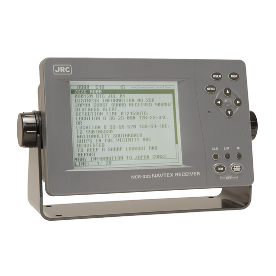
Navtex receiver
Hide thumbs
Also See for NCR-333:
- Brochure (2 pages) ,
- Instruction manual (136 pages) ,
- Operation card (2 pages)

Related Manuals for JRC NCR-333


Summary of Contents for JRC NCR-333
- Page 1 NCR-333 NCR-333 NAVTEX RECEIVER NAVTEX RECEIVER INSTRUCTION INSTRUCTION MANUAL MANUAL...
- Page 3 Preface Thank you for purchasing NCR-333 NAVTEX Receiver. The NAVTEX receiver automatically receives NAVTEX service broadcasts supplied in English and other optional languages. • Be sure to read this manual for full comprehension before using the equipment. • Save this manual near at hand for quick reference in the future.
-
Page 4: Before Operation
Before Operation Concerning the symbols This manual uses the following symbols to explain correct operation and to prevent injury or damage to property. The symbols and descriptions are as follows. Understand them before proceeding with this manual. WARNING Indicates a warning that, if ignored, may result in serious injury or even death. -
Page 5: Handling Precautions
Handling Precautions WARNING Do not disassemble or customize this unit. Doing so may cause fire, electrical shock or malfunction. Do not get this equipment wet or spill any liquids on or near this equipment. Doing so causes electrical shock or malfunction. Do not use a voltage other than specified. - Page 6 Handling Precautions CAUTION Do not use this equipment for anything other than specified. Doing so may cause malfunction or damage to persons. Do not adjust the trimmer resistors or the trimmer capacitors on the PCB unit. Doing so may cause malfunction or damage to persons. They are preset at the factory.
-
Page 7: External Views
External Views NCR-333 NAVTEX Receiver NAW-333 NAVTEX Antenna... - Page 8 NBG-319 Power Supply Unit NBG-320 Power Supply Unit...
-
Page 9: Table Of Contents
1.3.3 Configuration ..................1-3 1.4 Outline ..................... 1-4 2. INSTALLATION DIAGRAM ................2-1 3. PART NAMES AND FUNCTIONS ..............3-1 3.1 NCR-333 NAVTEX Receiver ..............3-1 4. DISPLAYS ..................... 4-1 4.1 Displays ....................4-1 4.1.1 Message text screen ................4-1 4.1.2 Message list 1 screen ................ - Page 10 6.3.5 MAINTENANCE menu (MAINTENANCE)..........6-46 6.3.5.1 Self Diagnosis (SELF DIAGNOSIS) ..........6-47 6.3.5.2 NAVTEX alarms (NAVTEX ALARM)..........6-50 6.3.5.3 Setting status of the NAVTEX Receiver (STATUS) ......6-52 6.3.5.4 Port monitor (PORT MONITOR)............6-53 6.3.5.5 Software version (SOFTWARE VERSION) ........6-56 6.3.6 The display language setting (LANGUAGE) ........
- Page 11 9.2.1 Electrical characteristics ............... 9-3 9.2.2 Environmental condition ................ 9-3 9.3 POWER SUPPLY UNIT (NBG-320 - Option) ........... 9-3 9.4 POWER SUPPLY UNIT (NBG-319 - Option) ........... 9-3 Appendix LOCATION & TIME SCHDULE FOR NAVTEX COAST STATIONS Environmental information...
-
Page 13: General
● Message saving function ━━━━━━━━━━━━━━━━━━━━━━━━━━━━━━━━━━━━━━━━━━━ NCR-333 can store up to 200 message identification codes for 70 hours. Moreover, the stored message of each channel can be saved up to 50 messages permanently. ● Automatically receiving station setting function ━━━━━━━━━━━━━━━━━━━━━━━━━━━━━━━━━━━━━━━━━━━... -
Page 14: Components
Operation card 7ZPJD0306A Antenna cable 7ZCJD0251 0.5 m 1.3.2 Options Options Type Quantity Remarks NAVTEX Antenna NAW-333 Whip antenna for NCR-333 Power supply unit NBG-319 12 / 24V input Power supply unit NBG-320 100/220V Manual Setting External printer DPU-414 Printer cable 7ZCJD0254A D-sub 9-pin 1.5 m... -
Page 15: Configuration
1.3.3 Configuration • System Block Diagram NAW-333 NAVTEX ANTENNA NCR-333 (OPTION) NAVTEX RECEIVER DPU-414 PRINTER (OPTION) DC +12V DC +6.5V NBG-320 POWER SUPPLY NKG-91 (OPTION) PRINTER (OPTION) NBG-319 POWER SUPPLY (OPTION) DC +12/24V AC 100/220V... -
Page 16: Outline
Outline • Outline Drawing of NCR-333 NAVTEX Receiver ━━━━━━━━━━━━━━━━━━━━━━━━━━━━━━━━━━━━━━━━━━━ Unit: mm Mass: approx. 2.1 kg... - Page 17 • Outline Drawing of NAW-333 NAVTEX Antenna ━━━━━━━━━━━━━━━━━━━━━━━━━━━━━━━━━━━━━━━━━━━ Unit: mm Mass: approx. 0.3 kg...
- Page 18 • Outline Drawing of NBG-319 Power Supply Unit ━━━━━━━━━━━━━━━━━━━━━━━━━━━━━━━━━━━━━━━━━━━ ±0.5 Unit: mm Mass: approx. 0.9 kg • Outline Drawing of NBG-320 Power Supply Unit ━━━━━━━━━━━━━━━━━━━━━━━━━━━━━━━━━━━━━━━━━━━ ±0.5 Unit: mm Mass: approx. 3.3 kg...
- Page 19 • Outline Drawing of DPU-414 Printer ━━━━━━━━━━━━━━━━━━━━━━━━━━━━━━━━━━━━━━━━━━━ Unit: mm Mass: approx. 0.7 kg...
- Page 20 • Outline Drawing of NKG- 91 Printer ━━━━━━━━━━━━━━━━━━━━━━━━━━━━━━━━━━━━━━━━━━━ ● Flush mount type Unit: mm Mass: approx. 0.8kg ● Wall mount type Unit: mm Mass: approx. 1.5kg...
-
Page 21: Installation Diagram
2. INSTALLATION DIAGRAM Notes: CAUTION Leave installation of this system to our service center or agents. Installation by an unauthorized person may result in malfunction. -
Page 23: Part Names And Functions
3. PART NAMES AND FUNCTIONS NCR-333 NAVTEX Receiver ● Front view LCD Panel For further information, refer to “● Display indicators” and “4. DISPLAY”. A: Key Panel USER Key DISP Key Displays the screen assigned to this key. Changes the screen, refer to “4. DISPLAY”. - Page 24 ● Rear view Protective cover To connect the antenna cable and the power cable, remove this cover. External equipments connector ECDIS, external buzzer, and MPD (Multi purpose display) cables are connected to the connector. Printer/Maintenance connector Serial printer and Maintenance PC cables are connected to the connector.
- Page 25 ● Rear panel (Terminal) ― ― ― Terminal Number and Name Description ANT + Connect an antenna cable. ANT - BK + Connect the key lines leading from the transmitter. BK - Connect the INS / External GPS cable for serial communication.
- Page 26 The channel number is displayed while receiving message on the channel. : 518kHz : 490kHz : 4209.5kHz NAVTEX Alarm ‘ALR’ is displayed while NAVTEX alarm has occurred. Refer to “6.3.5.2 NAVTEX alarm”. SAR message When a search and rescue (SAR) message is received with the buzzer sound.
-
Page 27: Displays
After NCR-333 is started, a message text screen is displayed. 4.1.1 Message text screen Message text screen displays the text of the received message. This screen is displayed after NCR-333 is turned on, or after receiving a message. Title Bar The following items are displayed. -
Page 28: Message List 1 Screen
4.1.2 Message list 1 screen Message list 1 screen displays the list of the stored messages. This screen is displayed by indicating ID, FREQ, LINES, DATE (DD/MM/YY), TIME, STATION and Message Type of each message. Move the cursor up/down to select the message, and press the ENT key to display the message text. -
Page 29: Select Message List Screen
4.1.4 Select message list screen Select message list screen displays the list of the selected messages. This screen is displayed by indicating ID, FREQ, LINES, DATE (DD/MM/YY), TIME, STATION and Message Type of each message. Move the cursor up/down to select the message, and press the ENT key to display the saved message text. -
Page 30: Setup Screen
4.1.6 Setup screen To display “Main menu”, press the MENU key. Refer to “6.3 MAIN MENU” for NCR-333 settings MAIN MENU ⅤⅢ 1.RX STATION_ 2.MESSAGE TYPE 3.DISPLAY 4.NAVTEX 5.MAINTENANCE 6.LANGUAGE: ENGLISH [EXIT]... -
Page 31: Installation
5.1 Installation 5.1.1 Selection of location The NAVTEX NCR-333 is designed so that it can be installed on either a desk, a wall, or the ceiling of the vessel. Select an installation location that satisfies the criteria listed on the followings. -
Page 33: Operation
- MAXIMUM - TYPICAL - MINIMUM - ALARM 3. BUZZER - ALARM MSG - RECEIVED MSG - NAVTEX ALARM - CLICK 4. LOCAL TIME 5. USER KEY SETTING 1. USER KEY 6. POS/TIME DISP. SET 4. NAVTEX 1. CHARACTER SIZE 2. -
Page 34: Basic Operation
15 seconds later. After diagnosis is finished, message text screen appears. Caution Check the main power supply of a switchboard, and a cable connection of NCR-333 NAVTEX Receiver when the power cannot be turned on. * SELF-DIAGNOSING... -
Page 35: Start Up (Abnormal-1)
When the result of “ROM CHECK” is “NG”, the sub screen may be displayed as shown in the following figure. Be sure to select "[START]" on the sub screen. In this case, although NCR-333 operates, the screen cannot display in languages other than English. -
Page 36: Start Up (Abnormal-3)
6.2.1.4 Start up (Abnorma-3) When the following screen is displayed, press and hold the PWR/CONT and DIM keys simultaneously until the power is turned off. Caution Contact our service center or agents. _ CHECK SUM COMPARING ERROR ! _ PLEASE RE-INSTALL THE PROGRAM. -
Page 37: Backlight Adjustment
CONT Notes The brightness becomes the brightest in the following case; - Failure alarm is occurred. (“NAVTEX ALARM” screen appears.) - After reception of “Navigational warnings” message (Message type “A”) - After reception of “Meteorological warnings” message (Message type “B”)) - After reception of “Search and rescue information, and pirate attack warnings”... -
Page 38: Alarm
CGC-300B), press the CLR key. An alarm buzzer beeps in the following case; - Failure alarm is occurred. (“NAVTEX ALARM” screen appears.) - After reception of “Search and rescue information, and pirate attack warnings” (Message type “D”) - After reception of “Navigational warnings” message (Message type “A”) - After reception of “Meteorological warnings”... -
Page 39: Displaying The Message
Additionally, the latest message text screen is displayed just after reception of message while opening any screen. IA01 31/12/05 18:20 JAPAN NAVTEX N.W. NR 1260/2005 KEIHIN KO, TOKYO EAST PASSAGE. DAYTIME DAILY UNTIL 08 JULY 2006 AREA BOUDED BY 35-35-37.9N 139-47-18.4E 35-34-58.9N 139-48-08.6E... - Page 40 Unread mark on the status bar shows unread messages has been received. IA01 31/12/05 18:20 Procedures JAPAN NAVTEX N.W. NR 1260/2005 KEIHIN KO, TOKYO EAST PASSAGE. DAYTIME DAILY UNTIL 08 JULY 2006 1) If the ENT key is pressed, the caution sentence...
- Page 41 The ‘ ‘ (‘ ‘) mark is displayed when the message text IA01 31/12/05 18:20 scroll downward (upward) is available. JAPAN NAVTEX N.W. NR 1260/2005 KEIHIN KO, TOKYO EAST PASSAGE. DAYTIME DAILY UNTIL 08 JULY 2006 Procedures AREA BOUDED BY 1) To move the cursor up/down to the next line, press 35-35-37.9N 139-47-18.4E...
- Page 42 Save the message Save the message The currently open message can be saved. IA01 31/12/05 18:20 JAPAN NAVTEX N.W. NR 1260/2005 The saved message is permanently stored in the data KEIHIN KO, TOKYO EAST PASSAGE. memory. DAYTIME DAILY UNTIL 08 JULY 2006...
- Page 43 Print the message Print the message The currently open message can be printed when IA01 31/12/05 18:20 JAPAN NAVTEX N.W. NR 1260/2005 having connected the external printer. KEIHIN KO, TOKYO EAST PASSAGE. DAYTIME DAILY UNTIL 08 JULY 2006 Procedures AREA BOUDED BY 35-35-37.9N 139-47-18.4E...
- Page 44 The data of currently opened message text can be IA01 31/12/05 18:20 output to the connected the external equipment (ECDIS, JAPAN NAVTEX N.W. NR 1260/2005 etc). KEIHIN KO, TOKYO EAST PASSAGE. DAYTIME DAILY UNTIL 08 JULY 2006 AREA BOUDED BY Procedures 35-35-37.9N 139-47-18.4E...
- Page 45 6.2.7.2 Message list 1 Press the DISP key several times. The list of the currently stored messages appears. This list shows a receiving station and a message type for each message. MSG LIST1 SORT:DATE FREQ LINES DATE TIME IA01 4209.5 09/06/04 12:34 STATION : YOKOHAMA MSG TYPE: NAVIGATIONAL WARNINGS...
-
Page 46: Message List 1
a. Select a message Screen scrolling 1 The ‘ ‘ (‘ ‘) mark is displayed when the message list 1 MSG LIST1 SORT:DATE FREQ LINES DATE TIME scroll downward (upward) is available. IA01 4209.5 09/06/04 12:34 STATION : YOKOHAMA Procedures MSG TYPE: NAVIGATIONAL WARNINGS KA04 09/06/04 10:34... - Page 47 b. Sort messages To search message quickly, messages can be sorted. MSG LIST1 SORT:DATE Procedures FREQ LINES DATE TIME IA01 4209.5 09/06/04 12:34 STATION : YOKOHAMA 1) Press the * key. The sub screen appears. MSG TYPE: NAVIGATIONAL WARNINGS KA04 09/06/04 10:34 STATION : KUSIRO 2) Select the “LIST”, and press the ENT key.
- Page 48 c. Put a check mark (Save/Unsave/print/output more than one message at the same time) Each checked message can be saved (printed or output) at the same time. MSG LIST1 SORT:DATE FREQ LINES DATE TIME IA01 4209.5 09/06/04 12:34 Procedures STATION : YOKOHAMA MSG TYPE: NAVIGATIONAL WARNINGS KA04 09/06/04 10:34...
- Page 49 d. Save messages Save one message MSG LIST1 SORT:DATE FREQ LINES DATE TIME The selected message can be saved. IA01 4209.5 09/06/04 12:34 STATION : YOKOHAMA MSG TYPE: NAVIGATIONAL WARNINGS Procedures KA04 09/06/04 10:34 STATION : KUSIRO *SET UP* 1) Move cursor to the message to save. MSG TYPE: NAVIGATIONAL WARNINGS LIST IA07...
-
Page 50: Message List 2
e. Unsave the saved message If the message is unsaved from the message list, “ ” mark displayed on the message list 1 or select message list will also be deleted. Caution The unsaved message will be deleted from the message list, if it is stored more than 70 hours. Unsave one message MSG LIST1 SORT:DATE... - Page 51 f. Print messages or the information on equipment Print one message MSG LIST1 SORT:DATE FREQ LINES DATE TIME The selected message can be printed. IA01 4209.5 09/06/04 12:34 STATION : YOKOHAMA MSG TYPE: NAVIGATIONAL WARNINGS Procedures KA04 09/06/04 10:34 STATION : KUSIRO *SET UP* 1) Move cursor onto the message to print.
- Page 52 3) Select the “[LIST]” or “[STATUS]”, and press the ENT key. [LIST]: The list of stored messages is printed. [STATUS]: The setting status is printed. The contents of "6.3.5.3 Setting status of the NAVTEX receiver" are printed. 4) Printing starts. After printing is completed, close the sub screen.
- Page 53 g. Output messages from an external port Output one message MSG LIST1 SORT:DATE FREQ LINES DATE TIME The external serial port outputs the selected message’s IA01 4209.5 09/06/04 12:34 data from DATA OUT port. STATION : YOKOHAMA MSG TYPE: NAVIGATIONAL WARNINGS KA04 09/06/04 10:34 Procedures...
- Page 54 6.2.7.3 Message list 2 Press the DISP key several times. The list of the currently stored messages appears. This list displays more messages on a screen than the message list 1 by not displaying “STATION” and “MSG TYPE”. MSG LIST2 SORT:DATE FREQ LINES...
-
Page 55: Select Message List
6.2.7.4 Select message list Press the DISP key several times. The list of the messages that is currently selected appears. Only the list of messages selected by “Message list 1” or “Message list 2” is displayed. SELECTED MSG SORT:DATE Ⅵ FREQ LINES DATE... - Page 56 a. Select the displayed message Select the displayed message The displayed message can be selected. SELECTED MSG SORT:DATE FREQ LINES DATE TIME IA01 4209.5 09/06/04 12:34 STATION : YOKOHAMA Procedures MSG TYPE: NAVIGATIONAL WARNINGS KA04 09/06/04 10:34 STATION : KUSIRO *SET UP* MSG TYPE: NAVIGATIONAL WARNINGS FILTER...
-
Page 57: Main Menu
Displays the menu for selecting message types (See 6.3.2) 3. DISPLAY: Displays the menu for setting the display unit. (See 6.3.3) 4. NAVTEX: Displays the menu for setting the NAVTEX receiver. (See 6.3.4) 5. MAINTENANCE: Displays the maintenance menu. (See 6.3.5) 6. LANGUAGE: Selects the menu display language. -
Page 58: Rx Station Screen
6.3.1 RX STATION screen To display RX STATION menu screen, select 1. RX STATION. RX STATION ⅤⅢ 1.RX MDOE: AUTO 2.OPERATING FREQ.:RX1/RX2/RX3 3.AUTO MODE SETTING 4.MANUAL MODE SETTING Fig.6-6 RX STATION menu screen Procedures 1. Press the ▲ ▼ key to select the menu item. 2. -
Page 59: Receiving Mode Setting (Rx Mode)
6.3.1.1 Receiving mode setting (RX MODE) The automatic select mode and the manual select mode for RX station : - AUTO: Automatic select mode When normal GPS position data is inputted, the position and NAVAREA of a ship are automatically specified, and the message of the receiving station in the NAVAREA is received. -
Page 60: Automatic Receiving Station Selection (Auto Mode Setting)
6.3.1.3 Automatic receiving station selection (AUTO MODE SETTING) To display AUTO MODE SETTING screen, select 3.AUTO MODE SETTING from RX STATION menu (6.3.1). Select the receiving station of each channel for every NAVAREA. STATION(AUTO) ⅩⅠ NAVAREA :ⅩⅠ FREQUENCY:RX1(518K) SELECT ALL A:JAYAPURA N:GUANGZHOU B:AMBON... - Page 61 a. Select receiving stations Select the receiving station of each channel for every NAVAREA. All stations of initial setting are “A message is received: ” Selection of NAVAREA STATION(AUTO) NAVAREA__:ⅠⅩ FREQUENCY:RX1(518K) Procudure SELECT ALL A:BUSHEHR B:HAMALA 1) Select NAVAREA, and press the ENT key. Cursor moves to the right side of ":"...
- Page 62 b. Cancel settings When the CLR/ MENU/ DISP/ USER key is pressed while setting up “a. Select receiving stations”, the information screen (the sub screen) as shown in the following figure is displayed. Select “OK” or “CANCEL”. Canceling the receiving station settings, and the screen changes according to the pressed key.
- Page 63 d. Save (or Clear) settings Save (or clear) the settings on the sub screen after setting up. Procedures STATION(AUTO) ⅩⅠ NAVAREA :ⅩⅠ FREQUENCY:RX1(518K) 1) Press the * key. The sub screen appears. SELECT ALL A:JAYAPURA N:GUANGZHOU Cursor is on the [CLEAR]. B:AMBON O:FUZHOU C:SINGAPORE...
-
Page 64: Manual Receiving Station Selection (Manual Mode Setting)
6.3.1.4 Manual receiving station selection (MANUAL MODE SETTING) To display MANUAL MODE SETTING screen, select 4.MANUAL MODE SETTING from RX STATION menu (6.3.5). Select the receiving station of each channel. There is no setup of NAVAREA. STATION(MANUAL) ⅩⅠ FREQUENCY:RX1(518K) SELECT ALL Fig.6-8 The receiving station selection screen (Manual mode setting) The items of the receiving station selection screen (manual mode) are as follows;... -
Page 65: Receiving Message Type Settings (Message Type Setting)
6.3.2 Receiving message type settings (MESSAGE TYPE SETTING) To display MESSAGE TYPE SETTING menu screen, select 2. MESSAGE TYPE SETTING. MSG TYPE ⅩⅠ FREQUENCY:RX1(518K) SELECT ALL A:NAV WARNINGS N:[SPARE] B:MET WARNINGS O:[SPARE] C:ICE REPORT P:[SPARE] D:SERCH & RESCUE Q:[SPARE] E:MET FORECAST R:[SPARE] F:PILOT SERVICE S:[SPARE]... -
Page 66: Display Setting Menu (Display Set)
- ALARM : +2 3.BUZZER : ON - ALARM MSG : ON (FOR MESSAGE TYPE:A,B,L) - RECEIVED MSG : ON - NAVTEX ALARM : ON - CLICK : ON 4.LOCAL TIME : ON (TIME DIFFERENCE): -11:59 5.USER KEY SETTING 6.POS/TIME DISP.SET(1):POS (2):TIME/NAV Fig.6-10 DISPLAY SET menu screen... -
Page 67: Contrast Adjustment (Contrast)
3.BUZZER - ALARM MSG : ON (FOR MESSAGE TYPE:A,B,L) - RECEIVED MSG : ON A buzzer is sounded. - NAVTEX ALARM : ON OFF: A buzzer is not sounded. - CLICK : ON BUZZER: OFF: All buzzer functions are disabled. -
Page 68: Time Difference Setting (Local Time)
6.3.3.4 Time Difference setting (LOCAL TIME) "LOCAL TIME" can set up time difference to UTC. When “ON” is selected, “(LT)” is displayed in the POSITION/TIME screen. The time of the POSITION/TIME screen displays the numerical value which added time difference to UTC. When “OFF”... -
Page 69: Assigning To The User Key (User Key Setting)
MAINTENANCE MENU MAINTENANCE menu screen is displayed. SELF DIAGNOSIS SELF DIAGNOSIS screen (MAINTENANCE menu) is displayed. NAVTEX ALARM NAVTEX ALARM screen (MAINTENANCE menu) is displayed. STATUS STATUS screen (MAINTENANCE menu) is displayed. PORT MONITOR PORT MONITOR screen (MAINTENANCE menu) is displayed. -
Page 70: Position/Time Screen Settings (Pos/Time Disp.set)
6.3.3.6 POSITION/TIME screen settings (POS/TIME DISP.SET) "POS/TIME DISP.SET" can set up the item displayed on the POSITION/TIME screen. POSITION/TIME screen can be displayed selecting items of “position (POS)”, “time (TIME)”, and “navigational information (NAV)”. 6.POS/TIME DISP.SET(1):POS (2):TIME/NAV Procudure 1. Select 6.POS/TIME DISP. -
Page 71: Navtexsetting Menu (Navtex)
6.3.4 NAVTEXsetting menu (NAVTEX) To display NAVTEX SET menu screen, select 4.NAVTEX from MAIN MENU (6.3). Character size, printer setting, etc. can be set up on this screen. NAVTEX SET ⅩⅠ 1.CHARACTER SIZE : NORMAL 2.CER DISP.SETTING : OFF (CER:CHARACTER ERROR RATE) 3.MESSAGE SCROLL... -
Page 72: Character Size Setting (Character Size)
04/06/09 12:34 IA01 4209.5 04/06/09 12:34 123400 UTC JUNE 04 123400 UTC JUNE 04 JAPAN NAVTEX N.W. NR 1260/2004 JAPAN NAVTEX N.W. NR 1260/2004 KEIHIN KO, TOKYO WEST PASSAGE. KEIHIN KO, TOKYO WEST PASSAGE. DAYTIME DAILY UNTIL 28 JUNE 2004 DAYTIME DAILY UNTIL 28 JUNE 2004 35-35-02.0N 139-47-55.3E,WGS-84... -
Page 73: Automatic Scrolling Setting (Message Scroll)
6.3.4.3 Automatic scrolling setting (MESSAGE SCROLL) When character size has been selected “LARGE”, a message text can be automatically scrolled on a screen. Select 3.MESSAGE SCROLL, and press the ENT key. Cursor moves to the right side of ":". Press the ▲ ▼ key and select the “ON” or “OFF”, and then press the ENT key. This setting is saved 3.MESSAGE SCROLL : ON The initial setting is “ON”... -
Page 74: External Printer Settings (Printer Property)
Press the ▲ ▼ key and select the following items. If the ENT key is pressed, Cursor moves to the lower line. The header and footer are added to a message text. OFF: Only a message text is printed. (The example of printing) Header ---- 518kHz NAVTEX MESSAGE ---- ZCZC IA01 TEST MESSAGE NNNN Footer --- END OF MESSAGE CER = 0.0% ---... - Page 75 6.3.4.6 External equipment message output settings (INS MSG OUTPUT SETTING) lNS port (DATA OUT) message output conditions can be set up when connecting external equipment. INS MSG OUTPUT SETTING ⅤⅢ STATION SELECT ALL 518k: AB-DEFGHIJKLMNOPQRSTUVWXYZ 490k: A-CDEFGHIJKLMNOPQRSTUVWXYZ 4.2M: -BCDEFGHIJKLMNOPQRSTUVWXYZ MSG TYPE SELECT ALL 518k: ABCDEFGHIJKLMNOPQRSTUVWXYZ 490k: ABCDEFGHIJKLMNOPQRSTUVWXYZ...
- Page 76 [ALL CLEAR] 4) To start save process, select [OK]. [OK] [CANCEL] Then, “SAVE OK” is displayed on the sub screen. Press the ENT or CLR key. NAVTEX menu screen appears. *INS MSG SET* NOW SAVING... [OK] [CANCEL] Saving is completed...
- Page 77 6.3.4.7 External printer message output settings (PRINTER MSG OUTPUT SETTING) Serial port (RS-232C: MAINTENANCE/PRINTER) message output conditions can be set up when connecting external printer. The external printer message output settings can be operated when the DATA OUT of 5.PRINTER PROPERTY is “AUTO”...
-
Page 78: Maintenance Menu (Maintenance)
Display alarm logs for disorders. (See 6.3.4.2) 3. STATUS: Display current status of NAVTEX setting. (See 6.3.4.3) 4. PORT MONITOR: Display serial data of each port. (See 6.3.4.4) 5. SOFTWARE VERSION:Display versions of software installed in NCR-333. (See 6.3.4.5) 6-46... -
Page 79: Self Diagnosis (Self Diagnosis)
2.LCD DIAGNOSIS) The outlines of menus are as follows; 1. SELF DIAGNOSIS: NCR-333 is diagnosed. (See a)) 2. LCD DIAGNOSIS: LCD panel is diagnosed. (See b)) 3. SELF DIAGNOSIS LOG: The diagnostic result log of the item 1 is displayed. (See c)) - Page 80 ‘DISP’ port is abnormal, ‘[3]’ is displayed. The power supply part is checked. ANTENNA CHECK Replace CMN-2333. The DC voltage of the NAVTEX antenna is checked. 518KHZ OVER ALL TEST Internal receiver (RX1) is checked. 490KHZ OVER ALL TEST Internal receiver (RX2) is checked.
- Page 81 b. The diagnosis of LCD panel (LCD DIAGNOSIS) Procudure 1) Select 2.LCD DIAGNOSIS, and press the ENT key. Cursor moves to the right side of ":". 2) Press the ▲ ▼ key and select the following items; START: Diagnosis is started. CANCEL: Diagnosis is canceled, and cursor returns to 2.LCD...
-
Page 82: Navtex Alarms (Navtex Alarm)
- "NO DATA" is displayed when NAVTEX alarm has not occurred. To print the NAVTEX alarms to the external printer, press the * key in order to display the sub screen. Select the “[PRINT OUT]”, and press the ENT key. Printing is started. - Page 83 Receiver 3 malfunction Unusual detection at the RX3 2) To print the NAVTEX alarms to the external printer, press the * key in order to display the sub screen. Select the “[PRINT OUT]”, and press the ENT key. Printing is started.
-
Page 84: Setting Status Of The Navtex Receiver (Status)
6.3.5.3 Setting status of the NAVTEX Receiver (STATUS) To display STATUS screen, select 3.STATUS from MAINTENANCE menu (6.3.5). The setting information of NCR-333 is displayed on the screen. STATUS ⅩⅠ NAVAREA: ⅩⅠ 518kHZ DISABLED STATION: A--D-----J----OPQR-------- 490kHZ DISABLED STATION: ---------J-------------XYZ 4209.5kHZ DISABLED STATION:... -
Page 85: Port Monitor (Port Monitor)
6.3.5.4 Port monitor (PORT MONITOR) Select 4.PORT MONITOR, and press the ENT key. PORT MONITOR screen appears. Select the port for monitoring. It can check whether data is normally outputted from the port. In addition, the displayed data can be stored temporarily to be rechecked. PORT MONITOR ⅩⅠ... - Page 86 a. The check of in/output data (PORT SELECTION) Procudure 1) Select 1.PORT SELECTION, and press the ENT key. Cursor moves to the right side of ":". 2) Press the ▲ ▼ key and select the following items; OFF: The monitoring of each port does not carry out. GPS IN: Input data of the GPS port DISP IN:...
- Page 87 c. Port log(PORT LOG) Procudure 1) Select 2.PORT LOG, and press the ENT key. PORT LOG screen appears. The data stored in the PORT MONITOR is displayed on this screen. 2) “ “ mark is displayed on the bottom line when the PORT LOG screen is able to be scrolled downward. “...
-
Page 88: Software Version (Software Version)
When MAINTENANCE menu screen is displayed, the present software version is displayed on the item 5. To display the MAIN MENU, press the CLR key. MANINTENANCE ⅩⅠ 1.SELF DIAGNOSIS 2.NAVTEX ALARM 3.STATUS 4.PORT MONITOR 5.SOFTWARE VERSION - PROGRAM : 02.00 - LANGUAGE: 01.00... -
Page 89: Maintenance And Inspection
7. MAINTENANCE AND INSPECTION The performance and longevity of this equipment depend on careful maintenance. To maintain the best performance, the following periodic inspections are highly recommended. CAUTION Keep the power supply voltage within the specified value (10.8 - 35Vdc). Know the condition of normal status when the equipment is properly functioning. -
Page 90: Periodic Inspection
7.2.2 Confirming the Alarm Status With referring 6.3.5.2, confirm that failure alarm is not occurring. If any alarm occurs, check the cause of the alarm. NCR-333 Alarm Table is followings. NCR-333 Alarm Table Failure alarm list (ALR sentence output) -
Page 91: Trouble Shootings
Check that the wiring of the power power supply unit or NCR-333. unit is correct. Check that the output voltage of the power unit or NCR-333 is correct. Power that the power unit supplies Replace the power unit. is out of range. -
Page 92: Maintenance Units
Maintenance units for repair are followings. Unit Name Model Note RX UNIT CMN-2333 CMJ-501N KEYBOARD UNIT CMD-953-1 NAVTEX ANTENNA NAW-333-1 ANTENNA for NCR-333 POWER SUPPLY UNIT NBG-319 DC: +12/24Vdc POWER SUPPLY UNIT NBG-320 AC:100/220Vac,DC:+24Vdc Whip Antenna 5ABBE00001 0.6 m Fuses... -
Page 93: After-Sales Service
8. AFTER-SALES SERVICE Warranty Warranty period is one year from the purchase day. Warranty Keeping period of maintenance parts is ten years from the production is discontinued. Before returning repair If what appears to be a malfunction is detected, refer to “7.3 Troubleshooting” to check if the equipment is actually defective before requesting repair. -
Page 95: Specifications
: F1B (3) Sensitivity : CER ≦ 1x10 at 1uV (CER: Character Error Rate) (4) Antenna input : 50 ohms for NAVTEX antenna 50 ohms for wide-band antenna High impedance for wire antenna 9.1.2 Operation panel (1) Type of display : 5.7-inch FSTN LCD, 320×240 dots... -
Page 96: Environmental Condition
Speed Over Ground (SOG) RMC, VTG Course Over Ground (COG) RMC, VTG Heading Rate of Turn Acknowledge alarm IEC61097-6 Request NAVTEX messages Set NAVTEX mask Output data IEC61162-1 Set alarm state IEC61097-6 NAVTEX received message Set NAVTEX mask 9.1.7 Received message log... -
Page 97: Navtex Antenna (Naw-333 - Option)
9.2 NAVTEX ANTENNA (NAW-333 - Option) 9.2.1 Electrical characteristics (1) Receiving frequency : 518kHz, 490kHz and 4209.5kHz (2) Bandwidth : 504kHz : ±20kHz 4209.5kHz : ±100kHz Consumption current : 6.5Vdc 23mA (Typ.) (4) Impedance : 50 ohms 9.2.2 Environmental condition (1) Operating temperature : -25°C to +55°C (IEC 60945) - Page 99 APPENDIX LOCATION & TIME SCHEDULE FOR NAVTEX COAST STATIONS Note: Based on status in 2005.
- Page 103 NAVAREA Ⅰ Range Freq Country Coast station Position Tx time (UTC) (nm) (kHz) Belgium Oostende 51 11N 02 48E T 0310,0710,1110,1510,1910,2310 59 30N 24 30E Estonia Tallinn U 0320,0720,1120,1520,1920,2320 Iceland Reykjavik Radio 0250,0650,1050,1450,1850,2250 64 05N 21 51W 0318,0718,1118,1518,1918,2318 Ireland Valentia 51 27N 09 49W W 0340,0740,1140,1540,1940,2340 55 22N 07 21W...
- Page 105 NAVAREA Ⅶ Range Freq Country Coast station Position Tx time (UTC) (nm) (kHz) Nambia Walvis Bay 23 03S 14 37E B 0010,0410,0810,1210,1610,2010 33 40S 18 43E C 0020,0420,0820,1220,1620,2020 South Africa Cape Town South Africa Port Elizabeth 34 02S 25 33E I 0120,0520,0920,1320,1720,2120 South Africa Durban 30 00S 31 30E...
- Page 107 NAVAREA ⅩⅠ Range Freq Country Coast station Position Tx time (UTC) (nm) (kHz) China Sanya 18 14N 109 30E M 0200,0600,1000,1400,2200 23 08N 113 32E N 0210,0610,1010,1410,2210 China Guangzhou 26 01N 119 18E O 0220,0620,1020,1420,2220 China Fuzhou China Shanghai 31 08N 121 33E Q 0240,0640,1040,1440,2240 38 52N 121 31E R 0250,0650,1050,1450,2250...
- Page 109 NAVAREA Ⅳ Range Freq Country Coast station Position Tx time (UTC) (nm) (kHz) Bermuda 32 23N 64 41W B 0010,0410,0810,1210,1610,2010 Canada Riviere-au-Renard 0020,0420,0820,1220,1620,2020 50 11N 66 07W 0035,0435,0835,1235,1635,2035 Canada Wiarton 44 20N 81 10W H 0110,0510,0910,1310,1710,2110 47 30N 52 40W Canada St.
- Page 111 NAVAREA Ⅵ Range Freq Country Coast station Position Tx time (UTC) (nm) (kHz) Argentina Ushaia 54 48S 68 18W M 0200, 1000, 1800 0600, 1400, 2200 Argentina Rio Gallegos 51 37S 65 03W N 0210, 1010, 1810 0610, 1410, 2210 45 51S 67 25W Argentina Comodoro Rivadavia...
- Page 112 APPENDIX ENVIRONMENTAL INFORMATION...
- Page 113 7ZPNB0008 Declaration on toxic & hazardous substances or elements of Electronic Information Products Japan Radio Company Limited (Names & Content of toxic and hazardous substances or elements : NCR-333 : NAVTEX Receiver (Type) (Name) (Toxic and Hazardous Substances and Elements)
- Page 116 +31-20-658-0750 Facsimile : +31-20-658-0755 e-mail : service@jrcams.nl SEATTLE Branch Telephone : +1-206-654-5644 Facsimile : +1-206-654-7030 MODEL NCR-333 MODEL NCR-333 e-mail : service@jrcamerica.com CODE No.7ZPJD0304B CODE No.7ZPJD0304B 01ETM ISO 9001, ISO 14001 Certified MAR. 2007 Edition 3 MAR. 2007 Edition 3...
Need help?
Do you have a question about the NCR-333 and is the answer not in the manual?
Questions and answers