Advertisement
Quick Links
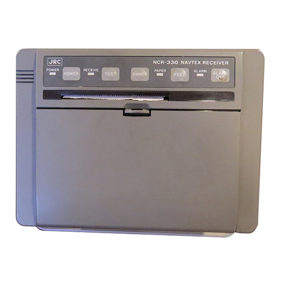
1. OPERATIONAL DESCRIPTION
No.
ITEM
1
Power lamp
2
Power on
(Normal)
Power on
(Initialize)
Power off
3
Receive lamp
4
Self-diagnostic
Test
5
Setting of
Illumination
6
Paper lamp
7
Feed the paper
8
Alarm lamp
9
Stop the Alarm
10
Menu start / end
11
Enable
12
Disable
OPERATION, INDICATION
Activate the green lamp to indicate that the power has
been turned on.
Press and hold POWER switch for at least two seconds.
While holding down TEST switch turn power back on by
pressing the POWER switch.
Press and hold POWER switch for at least two seconds.
This lamp turns on during signal detecting and blinks
during message text receiving.
Press TEST switch.
Press DIMMER switch.
This orange lamp blinks to indicate that equipment has
run short of paper.
Press FEED switch.
The red lamp blinks to indicate that an alert message
is received.
Press ALARM OFF switch.
Press MENU switch.
Press ENT switch.
Press CLR switch.
Advertisement

Related Manuals for JRC NCR-330


Summary of Contents for JRC NCR-330
- Page 1 1. OPERATIONAL DESCRIPTION ITEM OPERATION, INDICATION Power lamp Activate the green lamp to indicate that the power has been turned on. Power on Press and hold POWER switch for at least two seconds. (Normal) Power on While holding down TEST switch turn power back on by (Initialize) pressing the POWER switch.
- Page 2 Confirmation of Press STATE switch. Programmed Status Change the symbol Press ∆ , ∇ switch. Alphabet Symbol Alphabet Indicates the selected letter(B1 or B2). The lamp at the bottom right of the display Enabled: ON Disabled: OFF FUNCTION SETTING The equipment allows you to select a receiving coast station, a message type, and receiver status.
-
Page 3: Block Diagram
2.1 Introduction JRC NAVTEX Receiver, Model NCR-330 is designed in compliance with the IMO performance standard for narrow band direct printing telegraph equipment for the reception of navigational and meteorological warning and urgent information to ship. JRC NAVTEX Receiver is composed of Receiver, Main Processor. - Page 4 2.3 CMN-2330 RECEIVER 2.3.1 Composition The CMN-2330 Receiver is composed of following section: 1) Power supply section 2) Receiver section 3) Input/Output section 2.3.2 Specification of input and output Power supply section Input voltage : DC 10.8V∼35V Output voltage : +5V Receiver section Input frequency : 518kHz...
- Page 5 The generated signal is supplied to IC1 to get audio signal and the mixer IC (IC4) for self test. In the self test circuit, 516.3kHz fed from BFO is mixed with 1,700Hz ± 85Hz fed from Main Processor at the mixer (IC4) and 518kHz ± 85Hz is obtained. This signal is supplied to the receiver section via T3 to check the receiving circuit.
- Page 6 2.4 CDJ-2330 MAIN PROCESSOR 2.4.1 Composition The CDJ-2330 Main Processor is composed of following section: 1) Demodulator section 2) CPU section 3) Printer section 2.4.2 Description of operation 1) Demodulator section Demodulator section is composed of DSP(Digital Signal Processor), Codec and other IC.
Need help?
Do you have a question about the NCR-330 and is the answer not in the manual?
Questions and answers