Table of Contents
Advertisement
Quick Links
INSTALLER / CONSUMER
SAFETY INFORMATION
PLEASE READ THIS MANUAL
BEFORE INSTALLING AND USING
APPLIANCE.
WARNING!
IF THE INFORMATION IN THIS
MANUAL IS NOT FOLLOWED
EXACTLY, A FIRE OR EXPLOSION
MAY RESULT CAUSING
PROPERTY DAMAGE, PERSONAL
INJURY OR LOSS OF LIFE.
FOR YOUR SAFETY
Installation and service must be
performed by a qualified installer,
service agency or the gas suppler.
WHAT TO DO IF
YOU SMELL GAS:
•
Do not try to light any appliance.
•
Do not touch any electric switch; do
not use any phone in your building.
•
Immediately call your gas supplier
from your neighbor's phone. Follow
the gas supplier's instructions.
•
If you cannot reach your gas supplier,
call the fire department.
DO NOT STORE OR USE
GASOLINE OR OTHER
FLAMMABLE VAPORS AND
LIQUIDS IN THE VICINITY OF THIS
OR ANY OTHER APPLIANCE.
This appliance may be installed in an
after market permanently located
manufactured (mobile) home where not
prohibited by local codes.
This appliance is only for use with the
type of gas indicated on the rating plate.
This appliance is not convertible for use
with other gases unless a certified kit is
used.
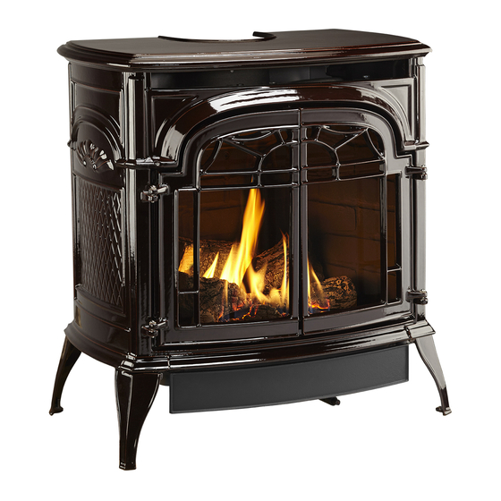
Radiance
Direct Vent/Natural Vent
Gas Heater
Model RDVOD: 3225 thru 3232,
3350 thru 3354, 3360 thru 3369,
3390 thru 3399
Homeowner's Installation
and Operating Manual
INSTALLER: Leave this manual with the appliance.
CONSUMER: Retain this manual for future reference.
4188
Radiance
cover
4/01
C E RT I F I E D
20004188 12/06 Rev. 16
Advertisement
Table of Contents

Subscribe to Our Youtube Channel
Related Manuals for Vermont Castings 3225


Summary of Contents for Vermont Castings 3225
- Page 1 MANUAL IS NOT FOLLOWED EXACTLY, A FIRE OR EXPLOSION Gas Heater MAY RESULT CAUSING PROPERTY DAMAGE, PERSONAL Model RDVOD: 3225 thru 3232, INJURY OR LOSS OF LIFE. 3350 thru 3354, 3360 thru 3369, FOR YOUR SAFETY 3390 thru 3399 Installation and service must be performed by a qualified installer,...
-
Page 2: Table Of Contents
Table Of Contents PLEASE READ THE INSTALLATION & OPERATING INSTRUCTIONS BEFORE USING APPLIANCE. Thank you and congratulations on your purchase of a Vermont Castings stove. IMPORTANT: Read all instructions and warnings carefully before starting installation. Failure to follow these instructions may result in a possible fire hazard and will void the warranty. -
Page 3: Installation & General Information
Radiance Direct Vent /Natural Vent Gas Heater Installation & Operating Instructions The Radiance Direct Vent/Natural Vent Room Heater, Model This appliance may be installed in an aftermarket* manu- Nos. 3350 thru 3354, 3360 thru 3369 and 3390 thru 3399, is a factured (mobile) home, where not prohibited by state or local vented gas appliance listed to the ANSI standard Z21.88b-2002 codes. -
Page 4: Operating Instructions Stove Dimensions
The Radiance stove is shipped from the factory as a Direct Vent Gas Heater. This heater may be converted into a Natural Vent unit in the field. If a Natural Vent Heater is desired, the Vermont Castings Z31D00 FSD- HAG Draft Hood must be directly installed to the top of the unit according to the installation instructions. -
Page 5: Installation Requirements
Radiance Direct Vent /Natural Vent Gas Heater Installation Requirements The installation must conform with local codes or, in the absence of local codes, with the National Fuel Gas Direct Vent System Only Code, ANSI Z223.1/NFPA 54 - latest edition. (EXCEP- TION: Do not derate this appliance for altitude. -
Page 6: Parallel Installation
Radiance Direct Vent/Natural Vent Gas Heater Parallel Installation: Minimum Clearance Wall Centerline from Floor and Flue Centerline, Direct Vent and Natu- ral Vent Direct Vent Only 42" (1070mm) Min. Alcove Width 4" (102mm) 48" (1220mm) Max. Alcove Depth 6" 6" (150mm) (150mm) ST130... -
Page 7: Gas Specifications
�� �� Vented Gas Fireplace Heaters �� �� �� The installation of your Vermont Castings stove �� must conform with local codes, or in the absence of �� local codes, with the National Fuel Gas Code ANSI �� Z223.1/NFPA 54 - latest edition, or CSA B149.1 May use up to ��... -
Page 8: Vertical Termination - Direct Vent Only
Radiance Direct Vent/Natural Vent Gas Heater Vertical Termination - Direct Vent ONLY Vent Termination Clearances A vertical vent system must terminate no less than 8’ When planning the installation, consider the location (2.44m) and no more than 40’ (12m) above the appli- of the vent terminal and clearances. -
Page 9: Vent Termination Clearances
Radiance Direct Vent /Natural Vent Gas Heater Vent Termination Clearances Your stove is approved to be vented either through the There must not be any obstruction such as bushes, side wall, or vertical through the roof. garden sheds, fences, decks or utility buildings within •... -
Page 10: General Venting Information - Termination Location
Radiance Direct Vent/Natural Vent Gas Heater General Venting Information - Termination Location INSIDE CORNER DETAIL ����� ����� ������ ������ ����� �������� ������ AREA WHERE TERMINAL IS NOT PERMITTED VENT TERMINATION AIR SUPPLY INLET CFM145a Canadian Installations US Installations A = Clearance above grade, veranda, porch, 12”... -
Page 11: Termination Clearances
Radiance Direct Vent /Natural Vent Gas Heater Termination Clearances Termination clearances for buildings with combustible and noncombustible exteriors. Inside Corner Recessed Location Outside Corner Combustible 6"(152mm) Combustible 6"(152mm) Noncombustible 2"(50mm) Noncombustible 2"(50mm) Balcony - Balcony - with no side wall with perpendicular side wall C = Maximum depth of 48"... -
Page 12: Venting Requirements And Options - Direct Vent Only
These (1) Finishing plate (CG) parts are available from DuraVent Corporation or your (1) Finishing collar (CG) Vermont Castings Dealer. (4) Charcoal Gray flue pipe rings See Figure 4 for dimensions relevant to the standard Starter Kit for Below-Grade Termination 7TDVSKS minimum-vent kits. -
Page 13: Assembly Procedures Tools Required
Radiance Direct Vent /Natural Vent Gas Heater Assembly Procedures WARNING Failure to position the parts in accor- dance with these diagrams or failure to use only parts specifically approved for use with this heater may result in property dam- age or personal injury. This heater and components are heavy. -
Page 14: Install Optional Fan
Radiance Direct Vent/Natural Vent Gas Heater WARNING This appliance is equipped with a three-prong (grounded) plug for your protection against shock hazard and should be plugged directly into a properly grounded three-prong receptacle. Do not cut or remove the grounding prong from this plug. Install the Optional Fan If you are installing the optional convection Fan Kit #2767 (FK26), continue here. -
Page 15: Venting System Assembly - Direct Vent
Radiance Direct Vent /Natural Vent Gas Heater 4. Attach the Inner Vent Assembly to the stove. Venting System Assembly - Direct Vent • Run a bead of sealant around the bottom end of General Information the starter pipe and attach the assembly to the stove The Radiance is approved for installation only with the using three 1/4-20 x 3/8”... -
Page 16: Install Vent Adapter Pipe (Simpson Dura-Vent Components)
Radiance Direct Vent/Natural Vent Gas Heater ST651 ST650 Fig. 23 Simpson Dura-Vent - install outer adapter pipe. Fig. 21 Fasten outer pipe with #12 x 1/2” sheet metal screw. Side Wall Termination Assembly Install the Vent Adapter Pipe 1. Locate the vent opening on the wall. Refer to Page (Simpson Dura-Vent Components) 6, Figure 5, to determine the opening centerline. - Page 17 Radiance Direct Vent /Natural Vent Gas Heater 6. Install the elbow using 3 sheet metal screws at each 12” joint. (305mm) Sleeve Max. Length 7. Measure, and cut if needed, the appropriate length of pipe section needed to make the connection through the wall.
-
Page 18: Vent Termination Below Grade
Radiance Direct Vent/Natural Vent Gas Heater 11. For CFM only: Install Charcoal Gray Pipe Rings (#7FSDRG) or Polished Brass Pipe Rings (#7FSDRP) Recessed Wall at pipe joints, if desired. Firestop Seal Both Termi- nal Ends Finishing Sheet Metal Collar Screws and Bracket Wall Screws and Anchors... -
Page 19: Venting System Assembly - Natural Vent
Direct Vent Heater. It may be converted to a Natural If an attic is above ceiling level, an attic insulation 12/99 Vent heater by installing the Vermont Castings Model shield must be installed. Z31D00 FSDHAG Draft Hood Adapter. The Radiance Heater is approved for installation as #7DVAIS a Natural Vent unit. -
Page 20: Install The Vent Pipe
Radiance Direct Vent/Natural Vent Gas Heater The Radiance stove, when installed as a Natural vent Install Log Set heater, includes a vent safety switch. (Page 34, Figure 67) Operating the stove when it is not connected to a Before beginning log installation, remove stove front properly installed and maintained venting system, or and glass frame. -
Page 21: Connect Gas Supply Line
Radiance Direct Vent /Natural Vent Gas Heater Rear Log Bracket Log rests on Lava Rock decorative grate LG155 LG158 Fig. 40 Completed log installation. LG155 Fig. 38 Radiance firebox. LG156 Radiance logs Right Rear Left Rear Log Top View Radiance logs installed Right Log 4/23/01 djt... -
Page 22: Burner Information
11.0” w.c. and maximum of 14.0” w.c. Burner Information The appliance must only use the gas specified on the rating plate, unless converted using a Vermont Castings ST315 Fuel Conversion Kit. To convert from LP to Natural Gas ST228 use Kit #000-5009. -
Page 23: Operation
Radiance Direct Vent /Natural Vent Gas Heater Operation The Radiance is shipped with the operable door front plate. The stove may be operated with the doors either open or closed. To open the front doors, insert the handle into the door latch stub and turn it to the right and up. -
Page 24: Lighting And Operating Instructions
Radiance Direct Vent/Natural Vent Gas Heater Lighting and Operating Instructions FOR YOUR SAFETY READ BEFORE LIGHTING WARNING:If you do not follow these instructions exactly, a fire or explosion may result causing property damage, personal injury or loss of life. A. This heater has a pilot which must be lit manu- •... -
Page 25: Troubleshooting - Honeywell #8420 Gas Control System
Radiance Direct Vent /Natural Vent Gas Heater Troubleshooting / Honeywell #8420 Gas Control System NOTE: Before troubleshooting the gas control system, be sure the external gas shutoff is in the “ON” position. WARNING: REMOVE THE GLASS PANEL BEFORE PERFORMING ANY GAS CONTROL SERVICE WORK. SYMPTOM POSSIBLE CAUSES CORRECTIVE ACTION... -
Page 26: Instructions For Rf Comfort Control Valve
Radiance Direct Vent/Natural Vent Gas Heater 7. If the manual switch is in the LOCAL position, the Instructions for RF Comfort Control Valve valve will be at the highest fixed pressure setting The Comfort Control valve allows remote control of and the fan will be at the highest fixed speed. -
Page 27: Fan Override During Auto Mode
Radiance Direct Vent /Natural Vent Gas Heater Auto Mode Pilot As- sembly In the AUTO mode, the room temperature, set tem- perature, flame and fan levels will be shown. AUTO will appear next to both the flame and fan icons. Blower When the control is in the AUTO mode, the main burner will turn on/off or modulate based on the heat needed... - Page 28 Radiance Direct Vent/Natural Vent Gas Heater Comfort Valve System Control Sequence Of Operation With Transmitter Set manual switch Five minute wait to local or remote period Light pilot burner Review LED fail- Did the LED stop ure analysis. blinking? Release pilotstat knob.
- Page 29 Radiance Direct Vent /Natural Vent Gas Heater Auto Path If the manual switch is set to REMOTE, Move switch from press the mode button LOCAL to REMOTE. to display AUTO on the Press any key within transmitter. Does the 30 seconds. transmitter display the room and temperture setting?
-
Page 30: Fuel Conversion Instructions
Radiance Direct Vent/Natural Vent Gas Heater Fuel Conversion Instructions WARNING! This conversion kit shall be installed Remove Screws Rear Log Bracket by a qualified service agency in accordance with the manufacturer’s instructions and all applicable Pilot codes and requirements of the authority having jurisdiction. - Page 31 Radiance Direct Vent /Natural Vent Gas Heater Lift Open Hi-Lo Knob Center Screw CO100 Fig. 55 Remove center screw from Hi-Lo knob. CO100 Gas conversion 3. Insert blue painted screw when converting to natural HI-LO knob 3/15/99 djt gas and red painted screw when converting to LP. 4.
- Page 32 Gas Conversion orifice. 6. Replace glass and stove front. 2. Remove and replace plug on lower right hand side Pilot (Vermont) Conversion is complete. of the valve; Red for LP and Blue for NG. (Page 26, 7/19/99 djt Fig. 49) 3.
- Page 33 Maximum 000-5003 #57 / .043” 20004587 #54 / .055” 20000130 27,500 35,000 000-5010 Table 2. Air Shutter Adjustment Model Natural Gas RDVOD, RDVOD with Vermont Castings Draft Hood Z31D00 FSDHAG 1” Fully Closed Minimum rear injector air inlet openings. 20004188...
-
Page 34: Maintenance
Radiance Direct Vent/Natural Vent Gas Heater Maintenance Your Radiance Gas Heater will provide years of service CAUTION with minimal upkeep. The following procedures will help ensure that your stove continues to function properly. TURN THE PILOT OFF BEFORE PAINTING. ALLOW THE HEATER TO COOL COMPLETELY Annual System Inspection BEFORE PAINTING. -
Page 35: Gasket Replacement
Do not use your stove if the flame pattern differs from the frame, and to clean the glass of any remaining that shown here. Contact your Vermont Castings dealer cement or bits of gasket. Use a cold chisel if neces- or a qualified technician for help. -
Page 36: Wiring Diagrams
Radiance Direct Vent/Natural Vent Gas Heater Wiring Diagrams POWER CORD On/Off Switch Wiring TP/TH Millivolt Chassis Gas Valve Ground Black ST124b Thermostat (Optional) Thermostat (Optional) Optional Thermostat Wiring FAN JUNCTION BOX St124b on/off/switch wiring Strain Relief 1/11/00 djt TP/TH ON / OFF Rheostat Millivolt Gas Valve... -
Page 37: Replacement Parts
CFM Corporation reserves the right to make changes in design, materials, specifications, prices and discontinue colors and products at any time, 4188 without notice. RDVOD parts 6/11/01 djt Radiance Direct Vent/Natural Vent Gas Heater (RDVOD) Models: 3225 thru 3232, 3350 thru 3354, 3360 thru 3369, 3390 thru 3399 Ref. Description RDVOD Gas Log Set, RDVOD 20004184... - Page 38 Radiance Direct Vent/Natural Vent Gas Heater Radiance Direct Vent/Natural Vent Gas Heater (RDVOD) Models: 3225 thru 3232, 3350 thru 3354, 3360 thru 3369, 3390 thru 3399 (continued) Ref. Description RDVOD Gasket, Glass Med. Knit - RDV40 1203702 Glass, GFP Firebox...
- Page 39 Radiance Direct Vent /Natural Vent Gas Heater Radiance Direct Vent/Natural Vent Gas Heater (RDVOD) Models: 3225 thru 3232, 3350 thru 3354, 3360 thru 3369, 3390 thru 3399 (continued) Ref. Description RDVOD Right End Refer to Enamel Parts Chart Page 38...
-
Page 40: Optional Accessories
Biscuit Maintenance 1556 Chestnut Brown The fan itself does not require regular maintenance, 1557 Ebony however, periodic cleaning of the fan and the surround- 1558 Vermont Classic Green ing area is required. 1562 Sand 1565 Bordeaux Installation 1566 Forest Green Refer to Page 14 for installation instructions. - Page 41 Radiance Direct Vent /Natural Vent Gas Heater 20004188...
- Page 42 Radiance Direct Vent/Natural Vent Gas Heater 4242 20004188...
-
Page 43: Warranty
Radiance Direct Vent /Natural Vent Gas Heater LIMITED LIFETIME WARRANTY PRODUCT COVERED BY THIS WARRANTY All Vermont Castings gas stoves, gas inserts, and gas fireplaces, and all Majestic brand gas fireplaces equipped with an Insta-Flame Ceramic Burner, or standard steel tube burner. BASIC WARRANTY •... -
Page 44: Energuide
Efficiency Ratings Model EnerGuide Ratings Fireplace Efficiency (%) RDVODRN 60.7 RDVODRP 60.7 RDVODRFN 60.7 RDVODRPN 60.7 CFM Corporation 2695 Meadowvale Blvd. • Mississauga, Ontario, Canada L5N 8A3 800-668-5323 • www.cfmcorp.com...
Need help?
Do you have a question about the 3225 and is the answer not in the manual?
Questions and answers
I'm looking at purchasing a Radiance direct vent. I need to know the least amount of stove pipe before you go horizontal.
The minimum vertical rise required before going horizontal for the Vermont Castings Radiance direct vent is 2 feet.
This answer is automatically generated
@Mr. Anderson I only have one foot to cent of chimney pipe.