Volvo Penta IPS 350 Operator's Manual
Marine engines
Hide thumbs
Also See for IPS 350:
- Operator's manual (124 pages) ,
- Operator's manual (124 pages) ,
- Installations (2 pages)
Table of Contents
Advertisement
Advertisement
Table of Contents

Subscribe to Our Youtube Channel
Related Manuals for Volvo Penta IPS 350


Summary of Contents for Volvo Penta IPS 350
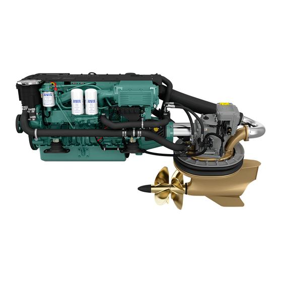
- Page 1 OPERATOR’S MANUAL VOLVO PENTA IPS 350/400/450/500/600...
- Page 2 Denne instruktionsbog kan bestilles på This operator’s manual is available in dansk. English. Bestillingskupon findes i slutningen af in- Complete the form at the end of the opera- struktionsbogen. tor’s manual to order a copy. Tämän ohjekirjan voi tilata myös suo- Diese Betriebsanleitung ist auch auf menkielisenä.
- Page 3 Please pay attention to the safety instructions contained in the manual. As owner of a Volvo Penta marine engine, we would also like to welcome you to a worldwide network of dealers and service workshops to assist you with technical advice, service require- ments and replacement parts.
-
Page 4: Table Of Contents
Identification numbers .......... 11 Seawater system ..........73 Presentation ............ 12-19 Fuel system ............77 Volvo Penta IPS – Inboard Performance System 12 Electrical system ..........80 Engine technical description ........ 14 Drive-unit .............. 85 Engine monitoring and EVC ........ 15 Propellers ............. -
Page 5: Safety Information
Read the operator’s manual carefully before operating or servicing the engine. If anything is unclear please contact your Volvo Penta dealer for assistance. This symbol is used in the book and on the engine to make you aware of safety information. -
Page 6: Boat Travel
Safety Information Safety precautions to be taken when operating the boat Your new boat Refueling Read operator’s manuals and other information When refueling there is always a danger of fire and supplied with your new boat. Learn to operate the explosion. - Page 7 Safety Information Carbon monoxide poisoning Most modern boats, however, are designed in such When a boat is moving forward, it will cause a certain a way that this problem is very rare. If suction should vacuum to form behind the boat. In unfortunate cir- arise anyway, do not open hatches or portholes at cumstances, the suction from this vacuum can be so the fore of the boat.
-
Page 8: Maintenance And Service
Loose clothing, hair, fingers or minimize the risk of fire and explosion. a dropped tool can be caught in the rotating parts of Using non-original Volvo Penta parts can result in fire the engine and cause serious personal injury. Volvo or explosion on board. -
Page 9: Lubrication System
Safety Information Hot surfaces and fluids Fuel system There is always a risk of burns when working with Always use protective gloves when tracing leaks. a hot engine. Beware of hot surfaces. For example: Liquids ejected under pressure can penetrate body the exhaust pipe, Turbo unit, oil pan, charge air pipe, tissue and cause serious injury. -
Page 10: Introduction
Introduction This operator’s manual has been compiled to help you get the most from your Volvo Penta engine. It contains all the information you need in order to operate and maintain your engine safely and correctly. Please read the operator’s manual carefully and learn how to operate the engine, controls and other equipment safely. -
Page 11: Certificated Engines
Warranty and Service book. Note that AB Volvo Penta’s liability is limited to that contained in the Warranty and Service Book. Read this book as soon as you take delivery of the engine. It contains important information about warranty cards, service and maintenance which you, the owner, must be aware of, check and carry out. - Page 12 ................with integral exhaust Engine(s) models covered by this declaration EC Type certificate number Volvo Penta IPS 350 (D4-260) Volvo Penta IPS 400 (D4-300) ........SDVOLV005 (noise) EXVOLV001 (exhaust) Volvo Penta IPS 400 (D6-310) Volvo Penta IPS 450 (D6-330) Volvo Penta IPS 500 (D6-370) Volvo Penta IPS 600 (D6-435) ........SDVOLV004 (noise)
-
Page 13: Identification Numbers
Introduction Identification numbers Always provide the engine and transmission identification numbers when ordering service or replacement com- ponents. The identification numbers are on an information decal located on the front edge of the engine. Note the infor- mation below. Make a copy of the page. Store the information so that it is available in event of the boat being stolen. -
Page 14: Presentation
Presentation Volvo Penta IPS – Inboard Performance System Volvo Penta IPS overvieiw Volvo Penta IPS is setting a new standard: Maneuvering and handling – Much improved efficiency, higher top speed, re- The reasons for the amazing maneuverability are: duced fuel consumption/extended range and great –... - Page 15 Presentation Environmental care Comfort The Volvo Penta IPS has been developed as a com- Volvo Penta IPS new technology leads to major im- plete system with excellent environmental perfor- provements for all comfort enhancing factors. mance as one of the main design targets. The very –...
-
Page 16: Engine Technical Description
Presentation Engine technical description Volvo Penta’s D6 is developed from the latest design in modern diesel technology. The engine has common rail fuel injection system, double overhead camshafts, 4 valves per cylinder, turbocharger, compressor, and after- cooler. The interaction of these, the large swept volume, and the EVC system results in exceptional diesel per- formance combined with low emissions. -
Page 17: Engine Monitoring And Evc
Presentation Engine monitoring and the EVC system Steering unit Helm station Control Unit (HCU) Servo Unit Steering (SUS) Helm station Control Unit (SHCU) CAN bus Power train Control Unit (PCU) Engine Control Unit (ECU) Engine monitoring system The engines are equipped with common rail system To protect the engine at too high coolant or charge air and electronically controlled injectors. - Page 18 Presentation The EVC system The Electronic Vessel Control (EVC) system is a so Engine speed and gear shift called distributed system. The principle of a distrib- Speed and gear shift contol is handled electronically uted system is to have "small" electronic units, called with dual function electronic controls.
- Page 19 Presentation Fuel level Fuel level can be displayed on the EVC system ta- chometer if a (0-180 ohm or 240-30 ohm) fuel level sender is installed in the fuel tank. The sender is con- nected to the PCU–engine cable harness. If a fuel level gauge is used it must be connected to the instru- ment serial communication bus.
-
Page 20: Orientation
2. Water shut off valve, drive-unit (only D6) 3. Turbocharger 4. Crankcase ventilation filter 5. Air filter 6. Aux stop 7. Compressor 8. Engine control unit 9. Generator 10. Oil filler cap 11. Volvo Penta IPS, Servo Unit Steering (SUS) -
Page 21: Presentation
Presentation D4-IPS, port Sea water filter 13. Sea water pump 14. Fuel filter 15. Oil dipstick, engine 16. Oil bypass filter 17. Oil filter 18. Charge air cooler 19. Cooling water intake 20. Oil dipstick, drive-unit 21. Water shut off valve, drive-unit 22. -
Page 22: Instrumentation
Instruments This chapter describes the instrument and control panels sold by Volvo Penta for your engine. If you want to supplement the instrumentation, or if your boat is equipped with instruments not described here, or you are not sure about their function, please contact your Volvo Penta dealer. -
Page 23: Start/Stop Panel
Instruments Start/stop panel The start/stop panel is used to start or stop the en- gine. The starter key on the main helm station must be in position “I” (driving position) for the engine to start. The engine can only be stopped if the control panel is activated. -
Page 24: Alarm Display
Instruments Alarm display (extra optional) The following warning lamps should never light up during operation. On the other hand, the warning lamps light up when the starter key is first turned to the drive position. Check that all lamps function. When the engine has started, all lamps should have gone out. - Page 25 Instruments Battery. (orange indication) The battery lamp lights up if the alternator is not charging. Stop the engine if this lamp lights up during operation. If the lamp lights up, this can be due to a fault in the electrical system or because the alternator drive belt is slack.
- Page 26 Instruments Coolant level (orange indication) The coolant lamp lights up when the coolant level is too low. Check coolant level. Please refer to “Maintenance: Fresh water system”. Red warning indication, serious fault If the red warning indication is shown during operation, a serious fault has occured.
-
Page 27: Evc Control Panel
Instruments EVC control panel The control panel is used in combination with the EVC system tachometer. The tachometer display shows oper- ating information and menus that can be navigated from the control panel. Tachometer display selection (twin installa- Activation button tion, port or starboard tachometer) Used to activate and lock the control panel and helm- Is used to select which of the engines menu systems... -
Page 28: Docking Station Panel
Instruments Docking Station Panel The docking station panel allow stopping and restarting of the engines and handling of faults when operating the boat from a docking station. The docking function (maneuvering with the joystick) is enabled when the docking station is activated. Please refer to the chapter “Operation”... -
Page 29: Evc System Tachometer
Instruments EVC System Tachometer Introduction Volvo Penta EVC System Tachometer presents rele- vant boat and engine information to the helmsman. In- formation is presented on a display in the tachometer. Information is depending on engine model, number of sensors and type of accessories. - Page 30 Instruments Trip menu (extra optional) In the TRIP MENU the user gets trip information from the EVC System and the user is allowed to select which view that should be presented in the EVC System Tachometers MAIN MENU as trip information. To get trip infor- mation following are required: Multisensor or NMEA 0183/NMEA 2000 compatible component (plotter, GPS, paddle wheel etc) Fuel level sender...
- Page 31 Instruments Gauges menu In GAUGES MENU the user gets information from analogue senders, placed on the engine. If the data is not available the parameter will not be displayed. When in GAUGES MENU, select view by turning NAVIGATION WHEEL. To select view as favorite, push NAVI- GATION WHEEL.
- Page 32 Instruments Settings menu In the SETTINGS MENU the user is allowed to set various options for the EVC system and to calibrate various parameters. IMPORTANT! For all settings and calibration procedures: Activate helm station by pushing the ACTIVA- TION BUTTON. NOTE! For twin installations always perform the settings on the port side system.
- Page 33 Instruments Depth alarm (extra optional) All depth alarm functions are accessed through this menu. A multisensor needs to be installed. DEPTH ALARM, ON/OFF Depth alarm can be switched ON/OFF. SET DEPTH Adjust the depth alarm value by turning the NAVIGA- TION WHEEL.
- Page 34 Instruments Select units and language Choose which units and languages to display. NOTE! Language and unit settings must be performed in all EVC system tachometers. US or METRIC 1. Activate helm station by pushing the ACTIVATION BUTTON. 2. Select SETTINGS from MAIN MENU by turn- ing NAVIGATION WHEEL.
- Page 35 There are two possible calibration methods for the fuel tank. One approximative, FULL TANK CALIBRATION, and one more precise, FUEL MULTIPOINT CALIBRATION. A fuel level sender need to be installed. NOTE! If FUEL TANK CALIBRATION is not shown in SETTINGS MENU, please contact your Volvo Penta dealer. FUEL MULTIPOINT CALIBRATION...
- Page 36 Instruments FUEL FULL TANK CALIBRATION When FUEL FULL TANK CALIBRATION is selected, the fuel level sender is calibrated in one step. This only gives an approximated value of the fuel level. There- fore all trip data concerning and based on, remaining fuel volume should be recognized as approximated values only.
-
Page 37: Speed Factor
Instruments Speed factor The speed factor for the boat´s paddle wheel speed sensor can be adjusted at a resolution of 1% and is used by the EVC to apply a correction to the output from the speed sensor. Set speed factor Set speed factor while driving the boat. -
Page 38: Evc System Display
Instruments EVC System Display (extra optional) Introduction Volvo Penta EVC system display is an instrument which displays operating information about the engine and allows you to communicate with the engine’s electrical system. Operation information is shown on an LCD display. - Page 39 Instruments Start image This is the starting image that is shown on the display for a brief period after starting. If the unit gives a constant audible warning after star- ting, the self-test has failed. The unit will still work, but may behave in an unexpected manner.
- Page 40 Instruments Set display contrast Press button 5 (furthest right) to set display contrast. Then press the appropriate buttons to adapt the le- vels, then save the settings by pressing EXIT. The display unit has 5 contrast settings. Configuration menu (button 5) (depressed for longer than 3 s) The configuration menu is used to: access the display mode SYSTEM INFORMA-...
- Page 41 Instruments Display mode System Information SYSTEM INFORMATION is a display mode that func- tions in the same way as the display in the tachometer (EVC System Tachometer). You navigate round these functions, using the buttons on the free-standing con- trol panel. In display mode SYSTEM INFORMATION there are several functions: - Display of operating information, information mes-...
- Page 42 Instruments ment intervals of the speedometers and tachome- ters. Rpm engine: [2500 rpm: 9000 r/min] in stages of 500 rpm - Speed: Change speed display (on/off) - Speed: [10 KNOT: 100 KNOT] in states of 10 (in the appropriate speed intervals) - Graph interval: 2 MIN,10 MIN, 30 MIN, 60 MIN, 2 H, 4 H, 8 H Units: (This menu is only displayed if LOCAL has...
- Page 43 Instruments Display mode Engine (Button 1) This display mode shows the engine speed and boat speed in the form of standard instruments, together with a trip computer and fuel level gauge. The fuel level gauge are displayed if there is a tank sender in- stalled.
- Page 44 Instruments Display mode Multi (button 2) This display mode shows operating information in four different windows (see below). The user can choose the operating information to be displayed in each win- dow. The information can be displayed as figures or as standard instruments.
- Page 45 Instruments Display mode Trip (button 3) This display mode shows: - Fuel used after last zeroing - Instantaneous fuel consumption (amount of fuel used per hour) (If speed information is available, in- stantaneous fuel consumption can also be calcula- ted in relation to distance.) - Operation time after last zeroing - Total operating time (can not be zeroed) Figure for single engine installation...
-
Page 46: Controls
Controls This chapter describes the controls sold by Volvo Penta for your engine. Electronic lever control Operation Both the shift function and engine speed control are controlled using the lever control. N = Neutral position (Drive-unit is disengaged and the engine runs at idle speed). -
Page 47: Friction Brake
Friction brake The control has a friction brake which can be adjusted as necessary to provide lighter or heavier lever action. Adjusting the friction brake: 1. Stop the engine. 2. Mover the control lever forwards so that the groove in the hub of the control lever is accessible. -
Page 48: Starting The Engine
Starting the engine Make it a habit to give the engine and engine bay a visual check before starting. This will help you to discover quickly if anything abnormal has happened, or is about to happen. Also check that instruments and warning dis- plays show normal values after you have started the engine. -
Page 49: Starting Method
Starting the engine Starting method Turn the ignition on Turn the starter key to position I to switch the ignition Check LEDs Each time the ignition is turned on, all LEDs are illumi- nated on the main control panel. Check that all LEDs function. -
Page 50: Start The Engine
Starting the engine Start the engine Start using the ignition switch Turn the key to position III. Release the key and let it key spring back to position I as soon as the engine has started. Stop cranking if the engine does not start with in 20 sek. -
Page 51: Operation
Operation Learn to handle the engine, controls and other equipment in a safe and correct manner before you cast off on your maiden voyage. Remember to avoid sudden or surprising rudder movements and gear shifting. There is a risk that passengers could fall over, or overboard. WARNING! A rotating propeller can cause severe injury. -
Page 52: Acknowleging Alarms And Messages
If the engine does not reach the full throttle range, this could be caused by a number of factors which are noted in the “Fault tracing” chapter. If the engine speed exceeds the full throttle range, select a coarser pitch propeller. Ask your Volvo Penta dealer for advice. -
Page 53: Synchronising Engine Speed
Operation Synchronizing engine speed When driving with twin engines, both the operating economy and comfort will be increased when the en- gines are operating at the same engine speed (rpm). When the synchronization function is activated, the engine speed (rpm) of the starboard engine is auto- matically adjusted to that of the port engine. -
Page 54: Operation
(via the exhaust pipe) into the stationary engine. Steering A boat with a Volvo Penta IPS drive-unit has more pro- gressive steering than a boat with a conventional drive or reverse gear. At half lock, the steering effect is more or less the same, and at full lock, the steering effect is stronger than for a boat with a conventional propeller. -
Page 55: Running Aground
If this is the case then the boat (if possible) should be run to harbor at reduced speed and taken out of the water and the drive-unit must be inspected at an authorized Volvo Penta workshop. -
Page 56: Docking (Joystick)
Operation Docking (Joystick) The Volvo Penta IPS docking function (joystick) makes it possible to rotate the boat and maneuver it in any direction – sideways, diagonally, forward and backward – with one hand. IMPORTANT! The the docking function (joystick) should only be used for docking (slow speed maneuvering). - Page 57 Operation Enabling boost mode In situations where normal thrust is insufficient, for ex- ample when it is windy or there is a strong current, the boost mode can be enabled. When the boost mode is enabled, the operator has more thrust available than in the normal docking mode.
- Page 58 Operation Maneuvering with the joystick WARNING! A rotating propeller can cause serious injury. Ensure that there is no one in the water before you enable docking mode. Never go near people who are bathing or where there is a risk that there are people in the water.
- Page 59 Operation Diagonally Rotate Turn...
-
Page 60: Operation
Operation Calibrating joystick function This calibration only needs to be performed if the boat movement does not corresponds to the movement of the joystick. Calibrate the joystick function as follows: IMPORTANT! When calibrating the joystick func- tion the boat must be operated in open water and under safe conditions. -
Page 61: Stopping The Engine
Stopping the engine The engine should be run for a few minutes at idle (in neutral) before turning it off. This will avoid boiling and even out the temperature. This is especially important if the engine has been operated at high engine speeds and loads. -
Page 62: Cold Weather Precautions
Stopping the engine Cold weather precautions To prevent freezing damage, the seawater system must be drained and the freshwater system coolant must have sufficient antifreeze protection. Refer to the cooling system section in chapter “Maintenance”. IMPORTANT! A poorly charged battery may burst as a result of freezing. -
Page 63: Maintenance Schedule
Maintenance schedule General information Your Volvo Penta engine and its equipment are designed for high reliability and long life. They are built to with- stand a marine environment, but also to have the smallest possible environmental impact. If given preventive maintenance, according to the maintenance schedule, and if Volvo Penta original spares are used, these quali- ties are retained and unnecessary malfunctions can be avoided. -
Page 64: Maintenance Schedule
Maintenance schedule Every 200 hours / at least once a year, included in extended protection: ● Crankcase ventilation filter. Change .............. page 64 ● Air filter Change ..................... page 64 ● Drive belts. Check belt tension ..............page 65 ● Compressor Check oil level ................page 66 ●... -
Page 65: Maintenance
Maintenance This chapter describes how to carry out the above maintenance. Read the instructions carefully before starting work. Maintenance intervals are contained in the chapter above: Maintenance schedule WARNING! Read the safety precautions for maintenance and service in the chapter: Safety Information, before starting work. -
Page 66: Engine, General
Maintenance: Engine general Changing air filter Remove the air filter cover. Remove the old air filter. Clean the air filter cover/housing if necessary. Take care not to allow impurities to enter the engine. Fit the new air filter and the air filter cover. Changing crankcase ventilation filter Unscrew the lid and remove the old filter. - Page 67 Maintenance. Engine general Checking drive belts WARNING! Stop the engine before commencing maintenance work. General Check belt tension and condition regularly. If the belt is too taut it can damage bearings and if it is too loose it may slip. Therefore, check the belt tension regularly.
- Page 68 Maintenance: Engine general Compressor. Checking oil Checking and topping up Unscrew and remove the dipstick. Wipe off oil. Screw the dipstick down fully and then remove it again. Check that the level oil is between the markings. If the dipstick is not screwed down fully the oil level will be slightly above the MIN marking if the oil level is cor- rect.
-
Page 69: Lubrication System
Lubrication system, Engine IMPORTANT! With a new or reconditioned engine, the oil and oil filters must be changed after 20–50 hours of operation. Use only the recommended grades of oil. Please refer to the “Technical Data” chapter. Oil change intervals can vary from 100 to 200 hours, depending on oil grade and sulphur content of the fuel. -
Page 70: Changing Engine Oil
Maintenance. Lubrication system Changing engine oil Always observe the recommended oil change interval. IMPORTANT! Only use a recommended grade of oil. Please refer to the “Technical Data” chapter. IMPORTANT! The oil level should always be between the MAX and MIN marks on the dipstick. Higher or lower oil level than permitted could lead to engine damage. - Page 71 Maintenance. Lubrication system Changing oil filter and bypass filter. Change the oil filter and bypass filter during each oil change. Remember to hand the old filters in to a re-cycling sta- tion. WARNING! Hot oil and hot surfaces can cause burns.
-
Page 72: Freshwater System
The coolant should contain ethylene glycol of a good quality with a suitable chemical consistency for an ade- quate protection of the engine. Using anti-corrosion aditive exclusively is not permitted in Volvo Penta’s engines. Never use water by itself as coolant. -
Page 73: Water Quality
(-18°F). (Using 60 % glycol lowers the freezing point to -54 °C (-65°F)). Never mix more than 60 % concentrate (Volvo Penta Coolant) in the cooling liquid, this will give reduced cooling effect and increase the risk of over- heating, and will give reduced freezing protection. -
Page 74: Checking Coolant Level
Maintenance. Freshwater system Checking coolant level WARNING! Do not open the engine coolant system filler cap when the engine is still hot ex- cept in an emergency. Steam or hot coolant may spray out. Turn the filler cap slowly counter clockwise and let any pressure escape from the system before remov- ing the cap. -
Page 75: Seawater System
Seawater system The seawater system is the boat’s external cooling system. On engines with drives, the seawater pump draws in water via the drive-unit, through the control system oil cooler to the seawater pump, after which the water passes the seawater filter before being pumped through the fuel cooler, intercooler, engine oil cooler and heat exchanger. - Page 76 Maintenance. Seawater system Cleaning seawater filter WARNING! Risk for water penetration. Screw off cover (1) and remove seal plate (2). Lift out and clean the insert (3). IMPORTANT! If the boat is used in water that has a lot of contaminants, seaweed etc. the filter must be checked more frequently than indicated in the maintenance schedule.
- Page 77 Maintenance. Seawater system Checking/Changing sacrificial anodes WARNING! Risk of water entering. Close the seawater cock before starting work on the sea- water system. 1. Close the seawater cock. 2. Drain the seawater as described in ”Draining the seawater system”. 3. Remove the sacrificial anodes in the heat ex- changer and the intercooler.
- Page 78 Maintenance. Seawater system Seawater system. Cleaning and inhibiting To prevent the build up of deposits and salt crystals in the seawater system it must be flushed with freshwa- ter. When the boat is laid up it must also be inhibited. WARNING! Risk of water penetration.
-
Page 79: Fuel System
Fuel system The engine fuel system is a so-called common rail-system. The advantage of the common rail-system is that the engine control unit controls the timing and fuel amount, this mean better emission control and a smooth running engine. All work on the engine common rail-system must be carried out at an authorized workshop. Use only the recom- mended grade of fuel: See the chapter “Technical Data”. -
Page 80: Bleeding The Fuel System
Maintenance. Fuel system Bleeding the fuel system The fuel system must be bled e.g. after changing fuel filter, if the fuel tank has been run dry and after long stops. WARNING! Never detach the pressure pipes. 1. Attach a transparent hose to the air vent valve (1). Lead the hose to a suitable receptacle to avoid spillage. -
Page 81: Maintenance
Maintenance. Fuel system Fuel pre-filter. Changing filter insert Close fuel cock at the fuel tank. Position a container under the fuel filter. Remove the cover by slackening off screw (1). Replace insert and reinstall cover. Open fuel cock. Vent fuel system. -
Page 82: Electrical System
Electrical system The engine is equipped with a two-pole system electrical system which means that the voltage (minus) is re- turned directly from the starter motor minus terminal with the battery negative lead. Individual components on the system return voltage to the starter motor minus terminal via separate cables. WARNING! Always stop the engine and break the current using the main switches before working on the electrical system. -
Page 83: Electrical Connections
Also check that all electrical connections are dry and free of oxidation and that there are no loose connec- tions. If necessary, spray these connections with a water-repellent spray (Volvo Penta Universal oil). Battery. Maintenance WARNING! Risk of fire and explosion. Never allow an open flame or electric sparks near the battery or batteries. - Page 84 Maintenance: Electrical system Battery. Charging WARNING! Danger of explosion! The batteries give off hydrogen gas during charging which when mixed with air can form an explosive gas – oxyhydrogen. A short-circuit, naked flame or spark can cause a large explosion. Ensure that the ventilation is good.
-
Page 85: Electrical Installations
Maintenance: Electrical system Electrical installations Leakage current from the electrical system can be caused by incorrect installation of electrical equip- ment. Leakage current can knock out the galvanic protection of components such as the drive, propel- ler, propeller shaft, rudder stock and keel and cause damage by electrolytic corrosion. - Page 86 All equipment connected to the auxiliary battery should have separate switches. To simultaneously charge two independent bat- tery circuits, fit a Volvo Penta charge distributor (accessory) to the regular generator.
-
Page 87: Drive-Unit
Volvo Penta IPS drive-unit The drive-unit is hydraulic, which means that forward/reverse engagement and disengagement is hydraulically activated. The drive-unit lubrication system has an oil filter and oil cooler. The drive-unit is equipped with sole- noid valves for electronically controlled shifting. - Page 88 Check that the space between the drive-unit housing and the clamping ring are entirely coated with corro- sion protection, Volvo Penta P/N 9510227. If the coat- ing needs to be renewed, follow the instructions below: 1. Clean and dry off the space between the housing and the clamping ring.
-
Page 89: Propellers
Propellers For best performance and fuel economy the engine speed should be within the maximum RPM range: See chapter “Operation”. If the engine speed at maximum RPM falls outside the max. RPM range then the propeller should be changed. WARNING! Make it impossible to start the engine when working on the propellers. Take the starter key out of the starter switch. - Page 90 Maintenance: Propellers Assembly 1. Apply water-resistant grease, part no. 828250 to the splines and thread on both propeller shaft. 2. Install the aft propeller. Then install the aft nut (C) and tighten it by hand until it bottoms. Install locking ring (5). Tighten the locking ring with the accompanying special tool and four socket cap screws (4).
-
Page 91: Laying Up/Launching
Laying up/Launching Before taking the boat out of the water for winter/out-of-season storage have an authorized Volvo Penta work- shop inspect the engine and other equipment. Have any necessary repairs or service work carried out so that your boat is in top condition for the new season. -
Page 92: Bringing Out Of Winter Storage
Laying up/Launching Bringing out of storage ● Connect the fully charged batteries. ● Check oil level in the engine and the drive-unit. Top up if necessary. If there is inhibiting oil in the ● Paint the hull, please refer to “Painting the under- system drain and fill with new oil, change oil filter. -
Page 93: Painting The Drive And Underwater Hull
Inspect the coating annually and scrape off any loose coating and apply a fresh coating. Volvo Penta recommends the coat- ing “Prop speed ® “. For instructions on how to apply the coating, please refer to the instructions that come with the “Prop speed ®... -
Page 94: In Case Of Emergency
In case of emergency Despite regular maintenance according to the maintenance schedule and perfect operation, faults may occur which must be attended to before the boat can travel further. This chapter contains tips for rectifying some of the possible faults. There are safety functions which are activated when certain faults occur, to protect the engine. -
Page 95: Emergency Shifting
In case of emergency Emergency shifting If a fault occurs which prevents the drive-unit from being operated (shifted) with the control lever it is possible to shift manually using the description below. WARNING! In emergency shifting, the unit is locked in forwards operation. Please note that the gear can not then be disengaged with the control lever. -
Page 96: Alignment Of Drive-Unit
In case of emergency Alignment of drive-unit If a fault occurs which prevents the drive-unit from be- ing operated with the steering wheel it is possible to align the drive-unit to straight forward manually using the description below. The tools needed during this operation are delivered in a special tool box together with the boat. - Page 97 In case of emergency 4. Turn the crank tool back 75 turns. The drive-unit is now aligned straight forward. 5. Remove crank tool. Disconnect the switch by pressing down the lock (2) and at the same time unplugg the switch by slowly wiggle it (please refer to procedure in step 1) Fit the plug.
-
Page 98: Fault-Tracing
A number of symptoms and possible causes of engine malfunctions are described in the table below. Always contact your Volvo Penta dealer if problems occur which you can not solve by yourself. WARNING! Read through the safety advice for care and maintenance work in the “Safety information”... -
Page 99: Diagnostic Function
In case of emergency Diagnostic function The diagnostic function monitors and checks that the engine, drive-unit and EVC system function normally. The diagnostic function has the following tasks: Discover and localize malfunctions ● Notify that malfunctions have been discovered ● Give advice in fault finding ●... -
Page 100: Malfunction Messages Steering System
In case of emergency Malfunction messages Steering system Tachometer display Pop-ups Steering System If the diagnostic function discovers a malfunction in steering system a steering specific pop-up will appear in the tachometer display.The pop-up is shown in the tachometer display and the ordinary boat information is not visible at all. - Page 101 In case of emergency Limited steering If there is steering function on only one driveline side, this pop-up is shown. At least one of the sides is able to shift gear and run the engine to be able to move the boat.
- Page 102 In case of emergency No gear/throttle and steering If there are multiple errors unabling the system to con- trol both steering and propulsion this pop-up is shown Steering malfunction on both sides. There are also a combination of errors unabling propulsion or control of propulsion through control levers on both sides.
-
Page 103: Malfunction Messages Engine And Evc-System
In case of emergency Malfunction message engine and EVC- system If the diagnostic function discovers a malfunction, it warns the driver by showing pop-ups in the tachom- eter display and the buzzer will sound. Pop-ups will alternate between "cause of fault" and "measures to take". -
Page 104: Fault List
In case of emergency Faults list A faults list can be viewed from the MAIN MENU in the tachometer, if a fault is registered. When in MAIN MENU, select FAULTS by pushing NAVIGATION WHEEL. Number after FAULTS indi- cates number of faults stored in faults list. Show faults in faults list by turning NAVIGATION WHEEL. -
Page 105: Fault Register
Empty the water trap underneath the fuel filters, please refer to Please refer to “Maintenance: Fuel system”. • Please contact a Volvo Penta workshop if the fault remains. Seawater pressure Explanation: Seawater pressure too low. Reaction: Engine power is reduced. - Page 106 Check coolant level. Please refer to "Maintenance: Freshwater system". • Check that no leakage occurs in auxiliary equipment connected to the engine cooling system. • Please contact a Volvo Penta workshop if the fault remains. Coolant pressure Explanation: Coolant pressure too low. Reaction: Engine power is reduced. Action: •...
- Page 107 Open the fuel taps and check that no leakage occurs. • Check that the fuel filters are not blocked. Please refer to “Maintenance: Fuel system” • Please contact a Volvo Penta workshop if the fault remains. Fuel temperature Explanation: Fuel temperature too high. Reaction: Engine power is reduced. Action: •...
- Page 108 Check that the oil filters are not blocked. Please refer to "Maintenance: Lubrication system". • Check that no leakage occurs. • Please contact a Volvo Penta workshop if the fault remains. Engine oil filter Explanation: Oil pressure differential too big. Reaction: Engine power is reduced. Action: •...
- Page 109 Action: • Check battery fluid level. • Check belt tension. • Please contact a Volvo Penta workshop if the fault remains. Auxiliary stop Explanation: External stop signal. Reaction: Engine stops or can not be started Action: • Check emergency stop button. Reset if necessary. Please refer to "Stopping the engine: Emergency stop"...
- Page 110 If the engine can not be operated from the chosen control panel, use an alternative control panel. • Please contact a Volvo Penta workshop if the fault remains. Lever calibration Explanation: Incorrect lever calibration. Reaction: It is not possible to choose active helm station.
- Page 111 Fault register System failure Explanation: Miscellaneous fault. Reaction: Action: • Restart engine(s). • Please contact a Volvo Penta workshop if the fault remains. Check joystick Explanation: Fault in joystick. Reaction: Engine power is reduced. Action: • Restart engine(s). • If the engine can not be operated from the chosen control panel, use an alternative control panel.
- Page 112 Reaction: Engine power is reduced on both sides. No steering. Action: • Restart both engines. • Please contact a Volvo Penta workshop if the fault remains. No gear/throttle and steering Explanation: Fault in steering system. Reaction: No steering. No propulsion. Action: •...
-
Page 113: Technical Data
Technical Data Engine General information D4 - See table below D6- See table below Volvo Penta IPS system designation ....... Engine model/after market designation ....See table below See table below Crankshaft power kW (hp)* ........See table below See table below Propellershaft power kW (hp)* ......... -
Page 114: Fuel Specification
Oil volume, oil filter ..........0.2 liter (0.4 US pint) Oil grade and viscosity ..........VP 1141634 (API GL5 SAE 75W/90) Synthetic Gear ratio ..............Volvo Penta IPS 350/400(D4) - 2.08:1 Volvo Penta IPS 400(D6)/450/500 - 1.94:1 Volvo Penta IPS 600 - 1.82:1... - Page 115 Notes...
- Page 116 Notes...
- Page 117 ✂ Yes please, I would like an operator’s manual in English at no charge. Publication number: 774 7996 Post or fax this coupon to: Document & Distribution Center Name Order Department ARU 2, Dept. 64620 Address SE-405 08 Göteborg Sweden Fax: +46 31 545 772 Orders can also be placed via the Internet:...
- Page 118 ✂ Sí gracias, deseo recibir gratuitamente un libro de instrucciones en español. Número de publicación: 774 8005 Franquear o enviar fax a: Document & Distribution Center Nombre Order Department ARU 2, Dept. 64620 Dirección SE-405 08 Göteborg Suecia Fax: +46 31 545 772 El pedido puede hacerse tam- bién por internet: http://www.volvopenta.com/...
- Page 119 ✂ Ja graag, Ik wil kosteloos een instructieboek in het Nederlands ontvangen. Publicatienummer: 774 8008 Stuur of fax de coupon naar: Document & Distribution Center Naam Order Department ARU 2, Dept. 64620 Adres SE-405 08 Göteborg Zweden Fax: +46 31 545 772 U kunt ook bestellen via internet: http://www.volvopenta.com/...
- Page 120 ✂ Sim, obrigado(a)! Gostaria de receber gratuitamente um manual de instruções em português. Número de publicação: 774 8014 Envie o talão pelo correio ou um fax para: Nome Document & Distribution Center Order Department Endereço ARU 2, Dept. 64620 SE-405 08 Göteborg Suécia Fax: +46 31 545 772 A encomenda também pode...
- Page 121 ✂ Evet lütfen, ücretsiz Türkçe kullanım el kitabı istiyorum Yayın numarası: 7748017 Bu kuponu şu adrese postalayın veya fakslayın: Ýsim Dokument & Distribution center Ordermottagningen Adres ARU 2, Avd. 64620 SE-405 08 Göteborg Ýsveç Faks: +46 31 545 772 Sipariþler Ýnternet üzerinden de verilebilir: Ülke http://www.volvopenta.com/...
Need help?
Do you have a question about the IPS 350 and is the answer not in the manual?
Questions and answers