Table of Contents
Advertisement
Advertisement
Table of Contents

Subscribe to Our Youtube Channel
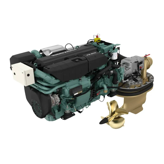
Related Manuals for Volvo Penta IPS800


Summary of Contents for Volvo Penta IPS800
- Page 1 OPERATOR’S MANUAL Volvo Penta IPS800, IPS900...
- Page 2 CALIFORNIA PROPOSITION 65 WARNING Engine exhaust, some of its constituents, and a broad range of engine parts are known to the State of California to cause cancer, birth defects, and other reproductive harm. Additionally, lubricants, fuels, and other fluids used in engines–including any waste created through the wearing of engine parts–contain or produce chemicals known to the State of California to cause cancer and birth defects or other reproductive harm.
-
Page 3: Table Of Contents
Content Foreword ...................... 2 Safety Information ..................3 Introduction ....................8 Instruments and Controls ................ 10 Optional ..................... 37 Starting ...................... 48 Operation ....................51 Engine Shutdown ..................55 Fault Handling ................... 58 Fault Code Register .................. 62 In Case of Emergency ................66 Maintenance Schedule ................ -
Page 4: Foreword
As owner of a Volvo Penta marine engine, we would also like to welcome you to a worldwide network of dealers and service workshops to assist you with technical advice, service requirements and replacement parts. Please contact your nearest authorized Volvo Penta dealer for assistance. -
Page 5: Safety Information
Check that you heave received the correct operator’s manual before you read on. If not, please contact your Volvo Penta dealer. This symbol is used in the operator’s manual and on the product, to call your attention to the fact that this is safety information. - Page 6 Safety Information Your new boat Fuel filling Read the instruction books and other information There is always a risk of fire and explosion during fuel carefully, which came with your new boat. Learn to filling. Smoking is not permissible, and the engine handle the engine, controls and other equipment in a should be stopped.
- Page 7 Safety Information Carbon monoxide poisoning When a boat moves forwards, an area of low pressure Most modern boats are designed so that the problem air forms behind the boat. In adverse conditions, this of low-pressure suction is very rare, however. If low- low pressure can be so strong that the boat’s own pressure suction does occur anyway, do not open exhaust fumes are sucked into the cockpit or cabin,...
- Page 8 Volvo Penta workshop. Using non-original Volvo Penta parts can result in fire or explosion on board. Lifting the engine When lifting the engine, use the lifting eyes installed Batteries on the engine.
- Page 9 Safety Information Hot surfaces and fluids Fuel system There is always a risk of burns when working with a Always use protective gloves when tracing leaks. Liq- hot engine. Beware of hot surfaces. For example: the uids ejected under pressure can penetrate body tis- exhaust pipe, turbo unit, oil pan, charge air pipe, sue and cause serious injury.
-
Page 10: Introduction
Introduction This Operator's Manual has been prepared to give you the greatest possible benefit from your Volvo Penta marine engine. It contains the information you need to be able to operate and maintain the engine safely and correctly. Please read the Operator's Manual carefully and learn to handle the engine, controls and other equipment in a safe manner before you cast off on your maiden voyage. - Page 11 Certification means that an engine type has been possible environmental impact. Through regular serv- checked and approved by the relevant authority. The ice and use of by Volvo Penta approved spare parts, engine manufacturer guarantees that all engines these qualities are retained.
-
Page 12: Instruments And Controls
Instruments and Controls This chapter describes the instruments, panels and controls Volvo Penta sells for your engine. If you would like to complement your instrumentation, or if your boat is equipped with instruments not described here, we ask that you contact your Volvo Penta dealer. - Page 13 Instruments and Controls Information Panel The information panel shows engine and operational information, messages and alarms. There is one information panel per driveline and helm station if no 7" screen is installed. The information shown can be set up according to per- sonal preferences.
- Page 14 Instruments and Controls Start/Stop Panel The start/stop panel is used for starting and stopping the engine frpm other stations than the main station. To start the engine it is necessary for the start key at the main station to be in the ”I” operating position. Read the starting instructions in chapter Start- ing page 48 and Engine Shutdown page 55 to ensure you use the correct start procedure.
- Page 15 Instruments and Controls Station Panel Activation Activate the helm station with a single press of the but- ton. Further pressure locks the helm station. To render the helm station inactive, hold the button down for 3 seconds. Inactive helm station P0001088 Active helm station Locked helm station...
- Page 16 Instruments and Controls Twin instalation Both engines in a twin instalation must be running before the docking station can be activated. The helm station is inactive. The helm station is active and the docking function is switched on. The helm station is locked. Start/Stop Press the STOP and START buttons to stop and start all engines.
- Page 17 Instruments and Controls Gauges These instruments are sold as engine options by Volvo Penta. RPMX1000 The tachometer displays engine speed; multiply the value shown on the dial by 1,000 to get the number of engine revolutions per minute. Engine hours is displayed in the tachometer window. When a function is activated a symbol shows shortly in the dispaly.
- Page 18 Prolonged expo- sure to strong sunlight can damage the screen and cause function faults. The Volvo Penta 4" screen is controlled by means of buttons on the panel: Return to the previous menu by pressing the button.
- Page 19 Instruments and Controls Engine View Information concerning the engine and its transmission is shown in Engine View. The information is shown in two windows; switch between the windows by pressing the arrow buttons. Up to six different pieces of operations data can be shown on the display.
- Page 20 Instruments and Controls Fuel This is the boat's trip computer and information is shown in two windows, Current Fuel and Average fuel. Switch between screens by pressing the arrow but- tons. Current Fuel • Instant fuel rateCurrent fuel consumption per hour. •...
- Page 21 Instruments and Controls Vessel Shows information regarding the boat's installation. The information shown can be set under Change gauge. Functions are also switched on and off here. Depending on the functions installed in the boat, the following can be displayed: •...
- Page 22 Instruments and Controls Trip Reset Zeroes all values in the trip computer. ACP Mode Setting the ACP protection position. For information on the ACP function, refer to ACP. Depth Alarm Setting the depth alarm function; refer to Depth Alarm page 113. Display Contrast Contrast adjustments affect all displays in the system.
- Page 23 Instruments and Controls Replace gauge In My View, Engine View and Vessel the owner can decide what information will be shown and where on the display. The procedure is the same for all views. 1 Press the MENU button and select Replace gauge. 2 Navigate using to the gauge for replace- ment and press...
- Page 24 Instruments and Controls 7" screen The Volvo Penta 7" screen is controlled by means of buttons: Turn to browse through submenus and to return to the main menu. Return to the previous menu. Confirms selection; also used to access sub- menus and the Settings page 28.
- Page 25 Instruments and Controls My View Boat, engine and transmission data are displayed in My View as analog or digital instruments. Selection of instruments to be displayed and their appearance is made under the Customize menu. Information for up to three engines can be displayed on the same screen in boats with multiple engine instal- lations;...
- Page 26 Instruments and Controls Removing instruments Turn to the Remove menu and press Turn to the instrument that is to be removed and con- firm with P0001184 Changing instruments Turn to the Modify menu and press Select the instrument that is to be changed and press Choose between: Remove, removes the instrument.
- Page 27 Instruments and Controls Engine Information concerning the engine and its transmission is displayed in this view. Depending on the functions installed in the boat, the following can be displayed: - Engine Speed - Rudder angle - Coolant Temperature - Voltage battery voltage - Engine oil pressure - Turbo pressure - Engine hours, total operating hours.
- Page 28 Instruments and Controls Fuel economy This view functions as the boat's trip computer. Depending on the functions installed in the boat, the following can be displayed: Current Fuel Instant fuel rate, based on current fuel consump- tion Instant fuel economy, current fuel consumption per hour.
- Page 29 Instruments and Controls Vessel Information concerning boat installations is displayed in this view. Depending on the functions installed in the boat, the following can be displayed: - Sea water temperature - Depth, to set the echo sounder refer to Depth Alarm in the Settings Menu page 112 chapter.
- Page 30 Instruments and Controls Settings Screen settings and different function settings are made in this view. Turn to the desired menu and press to access the submenus. Mode Choose between the modes Day ((dark text on a white background) or Night (light text on a dark background). Press switch between modes.
- Page 31 Instruments and Controls Components, press to see installed compo- nents. Software, information regarding the software ID number. Calibration The following is only displayed if the function is instal- led. For further information, refer to the relevant sec- tions in theSettings Menu page 112 chapter. Speed Correction, setting the speed factor.
- Page 32 Instruments and Controls Controls This section describes the controls Volvo Penta sells for your engine. Contact your dealer if your boat is equipped with controls other than those described here, and you feel uncertain about their function. Triple installation Both the adjustment of engine speed and the gear shift function are controlled using the control levers.
- Page 33 Instruments and Controls N = Neutral position. Reverse gear/drive disengage- dand engine at idle. F = Reverse gear/drive engaged for forward motion. R = Reverse gear/drive engaged for rearward motion. T = Engine rpm control (throttle). P0012501 Engine and drive features are controlled with push but- tons on the control.
- Page 34 Instruments and Controls The warning triangle lights up if the system discov- ers a fault; refer to Fault Handling page 58 for information. The warning triangle lights up on the same side as the driveline with the indicated fault. In triple instal- lations, both triangles light up if the center driveline registers a fault.
- Page 35 Instruments and Controls Adjusting the friction brake The control lever has a friction brake that can be adjusted for lighter or stiffer lever movement. Resist- ance in click mode can also be adjusted. 1 Switch off the engine. 2 Remove the cover (3). 3 Adjust the friction brake (1) and/or click mode (2) by turning the screw clockwise for stiffer lever move- ment, and counterclockwise for lighter lever move-...
- Page 36 Instruments and Controls Joystick The Volvo Penta Joystick is a control used for docking and maneuvering at low speed. Learn to use the joystick and its functions in a safe and proper manner before beginning to use the func- tion in confined marinas.
- Page 37 Instruments and Controls Docking When the docking function is activated, engine revo- lutions are limited and the boat can only be steered by the joystick. In order to activate the docking function, the following must be fulfilled: • engines running •...
- Page 38 Instruments and Controls High Mode If extra power, e.g. when there is a strong wind or strong current, the High Mode function may be engaged. Activate High Mode 1 Activate the joy stick by depressing the docking button (A). An audible signal confirms that the joy stick is activated and the docking button lights up.
-
Page 39: Optional
Optional Low speed The Volvo Penta low speed function is available for engines with hydraulic transmissions. Boats with powerful engines can have high speeds even at low revolutions; the low speed function reduces speed. N = Neutral position. Transmission is disengaged and engine revolu- tions are at idle. - Page 40 Optional Engaging the low speed function 1 Move the lever to the neutral position. 2 Press the Low Speed button on the control or on the helm station panel to activate the low speed function. An audible signal and the message “Lowspeed acti- vated”...
- Page 41 Optional Sport Fishing Mode The Volvo Penta sport fish function was developed for deep-sea fishing. When the function is activated, the IPS units are angled outwards and the helmsman can quickly rotate and maneuver forward/backwards to fol- low the movement of the fish. When activated, the wheel is disconnected and the boat is maneuvered solely via the control levers.
- Page 42 Optional Single lever Switching on the single-lever function 1 In order to activate the single-lever function, the control levers must in be roughly the same position, max 10% difference. Press the button to switch on the single-lever function. An audible signal and the message “Single lever activated”...
- Page 43 Optional IPS Dynamic Positioning System Volvo Penta IPS Dynamic Positioning system (DPS) is a function that aids holding a selected position and compass heading by means of a GPS signal. The function is intended as an aid e.g. while waiting for a berth or for a bridge to open.
- Page 44 Optional Show consideration! When the DPS is active, it gives rise to noise and heavy propeller wash that may annoy those around. You are responsible for the wake from your boat. WARNING! Check that nobody is in the water before engaging DPS.
- Page 45 Optional Activating the DPS The DPS can only be activated when boat speed is WARNING: below 3 knots. When DPS in Use Boat is Underway The function remains active for a maximum of 12 STAY OUT of hours. Maintain proper water –...
- Page 46 Optional Switching off the DPS The DPS can be switched off in one of the following ways: Moving the control levers out of the neutral position. • • Pressing the DPS button (1). • Activating the joystick with button (2). Two audible signals confirm that the DPS function is switched off and the DPS button (1) light goes out.
- Page 47 Optional • DPS cannot be activated. Control lever(s) not in neutral. Move lever(s) to neutral and activate the DPS. The control lever(s) must be in neutral position in order to engage the DPS. • DPS cannot be activated. The boat speed is too high.
- Page 48 Optional Volvo Penta ACP (Active Corrosion Protection) pro- tects against galvanic corrosion by controlling an elec- tric current that can be monitored by the engine elec- trical system. It is preferable to connect the boat to shore supply, if such is available. If shore power is unavailable, ACP utilizes the batteries.
- Page 49 Optional Settings ACP has three function modes; these are set in the Settings menu under ACP. A Normal means that the system is active and working in the optimal manner. B Chlorine Free means that the system has switched over to protection by the zinc anode for 4 h, resulting in no chlorine gas being given off.
-
Page 50: Starting
Starting Make a habit of visually checking the engine, engine bay and transmission before start. This will help you to discover quickly if anything abnormal has happened, or is about to happen. Also check that instruments and warning displays show normal values when you have started the engine. To minimize cold start smoke we recommend the installation of an engine heater or engine bay heater if temper- atures below +5°C (41°F) are encountered. - Page 51 Starting Starting the Engine Shifting and adjusting speed is only possible at an active station. On a boat with one station the station is always active. On a boat with two or more stations the main station automatically becomes active when the engine is started up with the ignition key(s).
- Page 52 Starting Start the engine If a station is locked the engines can only be started and stopped from this station. Start using the ignition switch Start using the ignition switch III. Release the key and let it spring back to position I as soon as the engine has started.
-
Page 53: Operation
Operation Learn to handle the engine, controls and other equipment in a safe and proper manner before casting off on your maiden voyage. Remember to avoid sudden and extreme rudder maneuvers and gear shifts. There is a risk for passengers and crew falling over or falling overboard. WARNING! A rotating propeller can cause serious injury. - Page 54 Operation Maneuvering Shifting between forward and reverse should be done at idling. Shifting at higher engine speeds can be uncomfortable for passengers and cause unnecessary stress on the transmission or cause the engine to stop. If you attempt to shift gear at an excessive engine speed, a safety function cuts in automatically, and delays shifting until engine speed has fallen to 1500 rpm.
- Page 55 Operation Helm Stations Changing and activating helm stations Helm station change 1 Move the control lever(s) to neutral. The neutral lamp (1) on the control lights up when the drive is in neutral. 2 Unlock the helm station being vacated, if it is locked, by pressing (2).
- Page 56 Fault Handling page 60 sedtion. Select a propeller with greater pitch if actual enginer- evolutions exceed the full throttle range. Contact your Volvo Penta dealer for advice. Triple installation Since the center propulsion unit is installed in a tunnel a slight efficiency loss for engine 2 is to be expected at cruising speed and wide open throttle.
-
Page 57: Engine Shutdown
Engine Shutdown Allow the engine to run at low idle, in neutral, for a few minutes after operations are completed. In this way after- boiling is avoided at the same time as temperature equalization takes place. This is especially important when the engine has been run at high rpm or under heavy load. - Page 58 Engine Shutdown Auxiliary stop If the engine cannot be stopped in a normal procedure, it is possible to stop the engine via auxiliary stop mounted on the side of the engine. After Engine Shutdown • Check the engine and engine bay for leakages. •...
- Page 59 Engine Shutdown Operation Break Operation break with the boat in water If the boat is not used, but left in the water, the engine must be warmed up at least once every fortnight. This prevents corrosion damage in the engine. If you expect the boat to be unused for two months or more, it must be inhibited, please refer to Storage.
-
Page 60: Fault Handling
Fault Handling Despite regular maintenance according to the maintenance schedule and perfect operation conditions faults may occur which must be attended to before the boat can travel further. This chapter describes alarms and fault handling. Alarm handling Message from engine and EVC system If a malfunction is discovered the driver is warned by a buzzer sounding and a message showing in the dis- play. - Page 61 Fault Handling Acknowledge message 1 Push OK to ackowledge the alarm. The buzzer becomes silent. 2 Read the message. 3 Push OK again and the message disappears. The alarm has to be acknowledged before the engine can be started. Faults list If a fault is registered Faults (Faults) is displayed in the information panel together with the number of faults.
- Page 62 A number of symptoms and possible causes of engine malfunctions are described in the table below. Always contact your Volvo Penta dealer if problems occur which you can not solve by yourself. NOTICE! Read through the safety advice for care and maintenance work in the Safety Information page 6 chapter before starting work.
- Page 63 Fault Handling 18. Faulty unit injectors 19. Insufficient air supply to engine: blocked air filter air leakage between turbocharger and engine inlet manifold fouled compressor section in turbocharger faulty turbocharger poor engine bay ventilation 20. Excessive coolant temperature 21. Too low coolant temperature 22.
-
Page 64: Fault Code Register
Fault Code Register CAUTION! Read the safety precautions for maintenance and service in the Safety Information chapter before starting work. When a malfunction is discovered the helmsman is warned by a sound alarm and at the same time a message is shown in the display. - Page 65 Engine power is reduced. Checking Engine Oil Level. Refer to Oil level, checking and topping up page 78. Check that no leakage occurs. Please contact a Volvo Penta workshop if the fault remains. Check EVC System Internal fault in EVC system. Engine performance might be affected.
- Page 66 Acknowledge fault by moving control to neutral and press OK-button. Check Steering Wheel Limited or no steering. Please contact a Volvo Penta workshop. Coolant Level Low coolant level. Check coolant level. Refer to Coolant Level, Checking and Topping Up page 87.
- Page 67 The engine has lost communication with a helm station. Engine power is reduced. Intake manifold temperature Charge air temperature too high. Engine power is reduced. Please contact a Volvo Penta workshop. Primary Battery Poor batteries or charging. Refer to Battery, Charging page 98. Steering failure Limited functionality.
-
Page 68: In Case Of Emergency
In Case of Emergency Despite regular maintenance according to the maintenance schedule and perfect operation, faults may occur which must be attended to before the boat can travel further. This chapter contains tips for rectifying some of the possible faults. There are safety functions which are activated when certain faults occur, to protect the engine. - Page 69 In Case of Emergency Starting Using Auxiliary Batteries WARNING! Explosion hazard. Batteries contain and give off an explosive gas which is highly flammable and explosive. A short circuit, open flame or spark could cause a vio- lent explosion. Ventilate well. WARNING! Never confuse the positive and negative poles on the batteries.
- Page 70 In Case of Emergency Emergency Steering Emergency Alignment, Propulsion Unit If a fault occurs which prevents one or several propul- sion units from being operated with the steering wheel it is possible to align the propulsion unit(s) for straight forward operation manually using the description below.
- Page 71 In Case of Emergency 1 Unscrew and remove the plug (1). Disconnect the cable by pressing down the lock (2) and at the same time wiggle the connector in “forward” position. 2 Connect the switch (3) and fit the red crank tool (4). 3 Press the switch button (5) down and keep it pressed while turning the crank tool carefully to an end position (6).
- Page 72 In Case of Emergency 4 Turn the crank tool back 75 turns (7). The propul- sion unit is now aligned for straight forward motion. 5 Remove the crank tool. Disconnect the switch (8) by pressing down the lock and at the same time unplugg the switch by slowly wiggling it.
- Page 73 In Case of Emergency Emergency steering with control levers If a fault occurs which prevents all propulsion units from being operated with the steering wheel, align all the propulsion units and use the steering method descri- bed below to reach nearest habor. If one or several propulsion units can be operated by the steering wheel, the steering method described below is not needed.
-
Page 74: Maintenance Schedule
Maintenance Schedule Your Volvo Penta engine and its equipment are designed for high reliability and long life. The engines are built to withstand the marine environment, but also to have the smallest possible environmental impact. If the engine and transmission are serviced regularly according to the schedule, these qualities will be retained and unnecessary malfunctions will be avoided. - Page 75 Maintenance Schedule Leakage and function check Drive-unit. Oil and oil filter Drive-unit. Function check of exhaust cock I, L Drive-unit and transom. Corrosion protection (sacrificial anodes) Batteries, electrolyte level 1) About 80% of the oil can be replaced from inside the boat. Every third oil change must be made with the boat on land. Oil change every 400 hours or every two years, whichever comes first.
-
Page 76: Maintenance
Care and maintenance work should be done with the engine stopped unless otherwise specified. Stop the engine before opening or removing the engine hatch/hood. Make it impossible to start the engine by removing the start key and cutting the system voltage with the main switches. 1 Volvo Penta IPS, Servo Unit 2 Engine oil filter and... - Page 77 Maintenance Engine, General General inspection Make a habit of visually checking the engine and engine bay before starting, and after operations when you have stopped the engine. This will help you to dis- cover abnormalities quickly, or if something is about to happen.
- Page 78 Maintenance Drive Belt, Check and Change WARNING! Stop the engine before doing any maintenance work. Check belt tension and condition regularly. The drive belt has an automatic tensioner and need not be adjusted. Check that the belt tensioner does not bot- tom.
- Page 79 Maintenance Drive belt, compressor The compressor is driven by a poly-vee belt by the engine flywheel. The belt has an automatic belt ten- sioner; manual adjustment of belt tension is therefore not required. Compressor, oil Follow the recommended oil change interval, see Maintenance Schedule page 72.
- Page 80 Maintenance Lubrication System Oil change intervals can vary depending on oil grade and sulphur content of the fuel, please refer toTechni- cal Data, Lubrication System. Oil change intervals must never exceed a period of 12 months. If you want longer oil change intervals than given in the table Oil Grade and Oil Change Interval, the condition of the oil must be checked by the oil manufacturers through regular oil testing.
- Page 81 Maintenance Engine Oil, Change Always follow the recommended oil change interval. Use an oil drain pump - an electrical oil drain pump is available as an accessory - to pump the oil out of the oil pan. 1 Run the engine until warm so that the oil is easier to pump.
- Page 82 Maintenance Oil Filter/By-pass Filter, Change Change the oil filter and bypass filter during each oil change. Remember to hand the old filters in to a re-cycling sta- tion. WARNING! Hot oil and hot surfaces can cause burns. 1 Put a suitable vessel underneath the filters to avoid oil spillage.
- Page 83 Maintenance Fuel System Only use the grades of fuel recommended in the fuel specification, see Technical Data, Fuel System. Always observe the greatest cleanliness during re- fuelling and work on the fuel system. All work on the unit injectors of the engine must be carried out by an authorized workshop.
- Page 84 Maintenance Fuel system, bleeding The fuel system must be vented, e.g. after changing fuel filter, if the fuel tank has been run dry and after long stops. 1 Put a suitable vessel underneath the hose. 2 Remove the protective cap from the venting nipple (1) on the filter bracket.
- Page 85 Maintenance Fuel pre-filter Volvo Penta fuel pre-filters are supplied in single and double models. Checks The double filter is fitted with a pressure gauge 1 that indicates when it is time to replace the filter cartridges. The filter cartridges must be replaced according to maintenance schedule recommendations, or earlier if the pressure gauge shows a pressure drop of 6–10 in.
- Page 86 Maintenance Replacing filter cartridges Double filter cartridges can be replaced while the engine is running, by shutting off the fuel flow to one filter holder at a time. Fuel flow is controlled by moving the lever (1) to the following positions: A Normal operating position (both filters connected).
- Page 87 The use of anti-corrosion agents alone is not permitted in Volvo Penta engines. Never use water alone as the coolant. The corrosion protection additives become less effec- tive over time, which means that the coolant must be changed at regular intervals;...
- Page 88 –24°C (–11°F). At 60% glycol concentration, the freezing point is lowered to –46°C (–51°F). Never mix more than 60% concentrate (Volvo Penta Coolant) in the coolant. A greater concentration pro- vides reduced cooling effect with the risk for overheat- ing and reduced frost protection.
- Page 89 Maintenance Coolant Level, Checking and Topping Up Checking the coolant level WARNING! Do not open the coolant filler cap when the engine is warm, except in emergencies, this could cause serious personal injury. Steam or hot fluid could spray out. The coolant level must be about 5 cm (2") below the expansion tank pressure cap sealing surface.
- Page 90 Maintenance 4 Fill with coolant to approx. 5 cm (2“) below the filler cap sealing surface. 5 Start the engine and let it idle for about 1 hour. IMPORTANT! Do not start the engine until the system is purged and completely filled. 6 Stop the engine and let it cool.
- Page 91 Maintenance Freshwater system, Flushing The cooling system should be flushed when the cool- ant is changed, to avoid loss of cooling performance due to deposits in the cooling system. 1 Drain the coolant, please refer to section Coolant, Draining page 88. 2 Put a hose into the filling hole in the heat exchanger and flush with fresh water.
- Page 92 Maintenance Seawater System The seawater system is the engine’s external cooling system. The seawater system sucks in water through the seawater inlet and pumps it through the heat exchanger and the reverse gear oil cooler. The system is protected from galvanic corrosion by means of zinc anodes located in the heat exchanger and the reverse gear oil cooler.
- Page 93 Maintenance Seawater System, Draining The seawater system must be drained in cold weather, if there is a risk of frost, to prevent frost damage. An alternative to draining is to keep the engine bay above freezing temperature, by means of a fan heater which is approved for outdoor use.
- Page 94 Maintenance Zinc Anodes, Check and Change WARNING! Risk of water entry. Close the seawater cocks before doing any work on the seawater system. 1 Close the sea cock. 2 Open the drain tap (1) on the heat exchanger and the tap (2) on the charge air cooler, and drain off the seawater.
- Page 95 Maintenance Impeller, Check and Change WARNING! Risk of water entry. Close the seawater cocks before doing any work on the seawater system. 1 Remove the seawater pump lid, and pull the impel- ler out with water pump pliers. 2 Check the impeller. If any cracks or other defects are visible, the impeller must be changed.
- Page 96 Maintenance Inlet Manifold, Checking the Drain Hole Water can condense in the charge air cooler during operation. The condensate is drained via a hole in the charge air cooler. Check that the drain hole is not blocked. IMPORTANT! If a large amount of water flows out of the drain hole, from the inlet manifold, the charge air cooler must be removed and proof tested.
- Page 97 Maintenance Electrical System The engine is equipped with a 2-pole electrical system and an alternator. System voltage is 12V or 24V. WARNING! Always stop the engine and break the current using the main switches before working on the engine. Main switch IMPORTANT! Never disconnect the current with the main switches when the engine is running, the alternator and elec-...
- Page 98 Volvo Penta workshop. P0007715 Electrical Connections Check that electrical connections are dry, free from oxide, and that they are securely tightened. Spray the connections as necessary with water-repellent spray (Volvo Penta universal oil). 47702095 04-2011...
- Page 99 Maintenance Battery, Maintenance WARNING! Risk of fire and explosion. Never allow an open flame or electric sparks near the battery or batteries. WARNING! P0002107 Never confuse the positive and negative poles on the batteries. Risk of arcing and explosion. WARNING! The battery electrolyte contains extremely corrosive sulfuric acid.
- Page 100 Maintenance Filling The electrolyte level should be 5–10 mm (0.2– 0.4”) above the cell plates in the battery. Top up with distilled water as required. After filling, the battery should be charged for at least 30 minutes by running the engine at idle. Some maintenance-free batteries have special instructions, which must be followed.
- Page 101 Maintenance • Charge batteries if they have become discharged. During charging, unscrew the cell plugs but leave them in the plug holes. Ventilate well, especially if the batteries are charged in an enclosed space. • If the engine is not used for a longer period of time, the batteries should be fully charged, then possibly trickle charged (please refer to the battery manu- facturer’s recommendations).
- Page 102 Maintenance 4 The start battery must have a main switch (1) con- nected to the battery's positive (+) side. The main switch must break the circuit to all equipment and be switched off when the boat is not in use. 5 If an auxiliary battery is used, a main switch must be placed between the auxiliary battery's positive (+) terminal and the circuit breaker panel for the...
- Page 103 While checking the oil level, ensure there are no signs of water dilution. The oil should have a golden brown hue. If the oil is thin and greyish it is probable water diluted. If so, always let the propulsion unit be checked by a Volvo Penta workshop. 47702095 04-2011...
- Page 104 Maintenance Changing oil and filter An oil change can be done either with the boat in the water or on land. An electric oil bilge pump is used if f the boat is in the water, according to option A. A com- plete oil change cannot be performed as the oil bilge pump cannot drain the IPS unit completely, approx.
- Page 105 Maintenance Corrosion protection, checking and changing Check the sacrificial anodes regularly. There are two anodes per stern drive; one is fixed to the drive and the other to the transom. Refer to the illustrations. Replace an anode when approximately 1/3 of it has corroded away.
- Page 106 Maintenance Inspect the drive unit anti-fouling Inspect the anti-fouling paint on the drive annually. All steel and bronze surfaces, including propellers, should be protected by anti-fouling paint for unpainted surfa- ces. Follow the anti-fouling paint supplier's instructions regarding how the paint must be used on the drive unit. Do not apply coating in the groove (A) between the drive unit and the hull or the plastic surface of the exhaust cushion (B).
- Page 107 The exhaust cock's lock shall be greased with water-resistant grease every year. IMPORTANT! If it is not possible to make the cocks work properly or if they have other malfunctions, please contact your Volvo Penta workshop. P0007396 47702095 04-2011...
- Page 108 Maintenance Propeller Damaged propellers should be replaced immediately oth- erwise there is high risk of serious damage to the propul- sion unit. Operating the boat with a damaged propeller should be undertaken with extreme care and only at reduced engine speeds. WARNING! Make sure the engine can not start during work on propeller(s);...
- Page 109 5 Mount the six socket cap screws. Torque 24-28 Nm (17.7–20.7 ft.lb.). 6 Push the spinner into place by hand. Install the center screw with Volvo Penta locking fluid 1161053 alternative Loctite 242. Pull the center screw, torque 24–28 Nm (17.7–20.7 ft.lb.).
-
Page 110: Storage
Storage Short Term Storage If the boat is not going to be used for a shorter period, the engines must be run up to normal operating tem- perature at least once every 14 days. This prevents corrosion in the engines. WARNING! If the engines must be run up to normal operating tem- perature with the boat kept up on land, make sure to... - Page 111 Storage Long Term Storage If the boat is not going to be used for a longer period than two months, either left in the water or layed up on land, a long-term preservation of the engine and pro- pulsion unit should be carried out. This ensures that the engine and propulsion unit are kept in good condi- tion and that no damage arises.
- Page 112 Storage • Clean the outside of the engine. Touch up any dam- aged areas of paintwork with Volvo Penta original paint. IMPORTANT! Never use a high-pressure washer when washing the engine and never point highpressure water jets directly at seals, rubber hoses or electrical compo- nents, as this could cause serious damage.
- Page 113 Storage Bringing Out of Storage The following should be carried out on each propulsion unit with the boat out of the water: Paint the hull. • • Check the sacrificial anode on the propulsion unit If there is less than 2/3 of the anode left, it must be replaced.
-
Page 114: Calibration And Settings
Calibration and Settings Settings Menu Settings and calibrations are managed in the Settings menu. 1 Navigate to the Settings menu. 2 Press to open the settings menu. 3 Navigate backwards and forwards in the settings menu by pressing Return to the previous menu by pressing the button. Settings Hold the button down for more than 3 seconds to get to the main menu. - Page 115 P0012516 Trip Reset Depth Alarm Setting the level for the depth alarm on Volvo Penta echo sounders. The setting need only be made at one helm station. 1 Navigate to Depth Alarm in the settings menu.
- Page 116 Calibration and Settings Set Offset 1 Go from the settings menu to Set Offset and press to reach the setting. 2 Use to set the depth compensation value so that it corresponds to the boat's lowest point or the waterline. The echo-sounder can be placed anywhere between these two points.
- Page 117 Calibration and Settings Display Contrast Adjust the screen contrast. The adjustment will affect all screens. Backlighting Contrast 1 Navigate to Display Contrast in the settings menu and press to open the submenu. 2 Use + and – to increase or reduce the contrast or backlighting.
- Page 118 Calibration and Settings Language Setting the language the information of the screen will be shown in. There are 10 languages to choose from. On boats with several helm stations and several screens it is enough to select a language in one station for it to be displayed at all of them.
- Page 119 3 Fill the fuel tank. Confirm that the fuel tank is full by pressing Full Fuel Tank Calibration IMPORTANT! Settings for Fuel Tank Volume, Empty Tank Calibra- tion and Fuel Alarm Level should only be carried out by an authorized Volvo Penta workshop. 47702095 04-2011...
- Page 120 Calibration and Settings Speed Factor The speed factor must be set while the boat is under way. Compare the displayed boat speed value with GPS data (or another boat) and adjust the speed factor until the values agree. The setting just needs to be done on one display for it to be shown at all stations and on all displays 1 Go from the settings menu to Speed Factor and press...
- Page 121 Calibration and Settings 1 Turn the ignition on and move the control levers to neutral. 2 Start the engines. Activate calibration mode by depressing the dock- ing button for 5 seconds. An audible signal confirms that docking mode is activated and the docking button lights up. 3 Move the joystick sideways as far as it will go in one direction.
- Page 122 Calibration and Settings Resetting the calibration 1 Turn the ignition on and move the control levers to neutral. Start the engines. 2 Activate calibration mode by depressing the dock- ing button for 5 seconds. An audible signal will confirm that docking mode is activated and the docking button lamp will light up.
-
Page 123: Technical Data
Technical Data Engine Type Designation IPS 800 IPS 900 Output at crankshaft* 441 kW (600 hk) @ 2300 rpm. 515 kW (700 hk) @ 2350 rpm. Output at propeller shaft* 417 kW (567 hk) @ 2300 rpm. 487 kW (662 hk) @ 2350 rpm. Max. - Page 124 Oil pressure during neutral min. 250 kPa (36.3 PSI) Compressor, oil Oil capacity 0.,09 litre (0.19 US pint) Oil quality Volvo Penta, art nr: 1141641 Oil Grade and Oil Change Interval Oil quality Sulphur content in fuel, by weight up to 0,5% 0,5–1,0%...
- Page 125 Cooling System Freshwater system capacity including heat exchanger approx. 39 liters (10.3 US gals) Coolant Volvo Penta Coolant VCS and VCS Ready Mixed (yel- low colour) are based on Organic Acid Technology, OAT. Volvo Penta Coolant and Coolant Ready Mixed (green colour) are silicate based.
- Page 126 Technical Data Water Quality ASTM D4985: Total solid particles <340 ppm Total hardness <9,5° dH Chloride <40 ppm Sulfate <100 ppm pH value 5.5–9 Silica (acc. ASTM D859) <20 mg SiO P0002094 Iron (acc. ASTM D1068) <0.10 ppm Manganese (acc. ASTM D858) <0.05 ppm Conductivity (acc.
- Page 127 Chassis number (2*) ........... Serial number (3*) ........... Product designation (8*) ........... Model, type: Rated power/speed B hp. C kw / D rmp AB VOLVO PENTA, SWEDEN MADE IN FRANCE EPA Engine family: 9VPXN10.8DCA P0010431 XXXXX XXXXXXX P0010442 Propulsion Unit Product designation (4*) ...........
- Page 128 Engine type ................4 stroke diesel engine with stern drive with integral exhaust Engine(s) models covered by this declaration EC Type certificate number Volvo Penta IPS 800 (D11-600) Volvo Penta IPS 900 (D11-700) ..........SDVOLV006 (noise) 49300-07 HH (exhaust) Essential requirements Standards Used Other normative document used Annex I.B –...
-
Page 129: Operator's Manual Order
(7–8 digits). http://vppneuapps.volvo.com/manual/coupon/ If internet access isn't possible, please contact your Volvo Penta dealer. All order information is stored internally at AB Volvo Penta and will not be shared with third parties. 47702095 04-2011... -
Page 130: Alphabetical Index
Alphabetical index IPS Dynamic Positioning System......36 4" Screen..............16 Joystick..............34 7" screen..............22 Long Term Storage..........109 Acknowledge message.......... 59 Low speed..............37 Adjusting the friction brake........33 Lubrication System........... 78 Air Filter, Check and Change........75 Alarm handling............58 Main switch.............
Need help?
Do you have a question about the IPS800 and is the answer not in the manual?
Questions and answers