
Related Manuals for Gfp 455 TH


Summary of Contents for Gfp 455 TH
- Page 1 Gfp 400 Series January 2011 OPERATING MANUAL Gfp 455 TH Gfp 463 TH Please read this manual carefully before operating!
-
Page 2: Table Of Contents
Gfp 400 Series January 2011 Table of Contents Contents Page Introduction …………………………………………………… Important Safety Instructions………………………………….. Installation Safeguards ……………………………………….. General Safeguards……………………………………………. Operating Conditions …………………………………………. System Components ………………………………………….. Control Panel …………………………………………………. Packing List ………………………………………………… .. Installation A. Uncrate the machine……………………………………. 10 B. Remove heat tube package……………………………... 10 C. -
Page 3: Introduction
Gfp 400 Series January 2011 1. Introduction Thank you for choosing a Gfp laminator. It has been designed and manufactured to provide years of continuous service. Please read this manual thoroughly before operating. Please inspect the box and the laminator for shipping damage. Damage should be brought to the attention of the delivering carrier immediately. -
Page 4: Installation Safeguards
Gfp 400 Series January 2011 3. Installation Safeguards • Shipping damage should be brought to the immediate attention of the delivering carrier • Avoid locating the laminator near sources of heat or cold. Avoid locating the laminator in the direct path of forced, heated or cooled air •... -
Page 5: General Safeguards
Gfp 400 Series January 2011 4. General Safeguards • Keep hands, long hair, loose clothing, and articles such as neckties away from rollers to avoid entanglement and entrapment. The rollers have pinch points that can trap body parts or clothing and cause serious injury •... -
Page 6: Operating Conditions
Gfp 400 Series January 2011 5. Operating Conditions Place machine on level surface Environment requirements: Ambient temperature: 50⁰ F - 104⁰ F Humidity:30%—80%;ideal humidity:55% Due to the static on film rolls, you should try to keep the environment clean. Provide enough space around machine to ensure the safe and effective operation. -
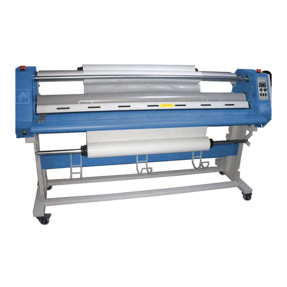
Page 7: System Components
Gfp 400 Series January 2011 6. System Components Linkage Axle 16. Exit table 2. Left cabinet 17. Rear rewind assembly 3. Rewind tube axle 18. Main power switch 4. Backing paper rewind tube 19. Fuse 5. Rewind tube positioning sleeve 20. -
Page 8: Control Panel
Gfp 400 Series January 2011 7. Control Panel 1. Cold laminating indicator 6. Hot / Cold heater switch 2. Hot laminating indicator 7. Forward / Reverse switch 3. Ready light indicator 8. Continuous/ foot pedal operation 4. Temperature display screen 9. -
Page 9: Packing List
Gfp 400 Series January 2011 8. Packing List Remove all parts from shipping create and boxes. Inspect parts and the machine carefully. Any missing parts should be reported to the shipper upon receipt of shipment. Main Machine Crate Stand Box... -
Page 10: Installation
Gfp 400 Series January 2011 Installation A. Uncrate the machine 1. Remove screws around the base of the crate including corner supports 2. Lift crate straight up and off the skid Crate B. Remove Heat tube package 1. Remove nuts on heater support brackets that hold the cardboard tube to the feed table and remove the heater package 2. -
Page 11: Remove Machine From Skid
Gfp 400 Series January 2011 9 C. Remove machine from skid 1. Remove plastic cover and accessory box. 2. Raise the In-feed table (# 1) and lock in place 3. Remove rewind tube by pushing toward the spring side 4. Remove supply shafts (# 2) from the crate base by loosening the hex bolts on core adapters and sliding to one side 1. -
Page 12: Assemble Machine Stand
Gfp 400 Series January 2011 Assemble machine stand 1. Remove stand from shipping box 2. Bolt cross members to stand side frame 3. Rear of stand has two (2) media hangers on the side frames, front of stand has one. -
Page 13: Set Machine On Stand
Gfp 400 Series January 2011 Heavy! Handle with care!! Warning: when moving the machine, you should have your hands holding on the upper supporting beam and the rear supporting beam. Do not use roller gap adjustment hand-wheel for lifting! 9 E. Set machine on stand 1. -
Page 14: Attach Supply Support Brackets
Gfp 400 Series January 2011 9 F. Attach front and rear supply shaft support brackets and insert supply shafts 1. Match letter on support brackets, A through D, with letter on inside of side frame, letters face in and are hidden when installed correctly 2. -
Page 15: Installing Heat Tube
Gfp 400 Series January 2011 10. Installing Heat Tube Warning: Do not attempt this with the power on! A. Insert Heat tube 1. Remove gap Hand wheel from right side cover 2. Remove the right and left cabinet covers. 3. Remove left and right heater support brackets 4. -
Page 16: Connect Electric Wires
Gfp 400 Series January 2011 10. Installing Heat Tube Connect electric wires 1. With the tube in place, remove the porcelain inserter, porcelain tube, hex nut and flat washer from both ends 2. Connect the two ends to the electric wire connectors. -
Page 17: Installing Take Up Reel
Gfp 400 Series January 2011 11. Installing Take up reel 1. Loosen the pressure-adjusting nut near the right cabinet, and the rewind tube can then be removed from the machine 2. Slide a paper tube onto the rewind tube by rotating away from the core stop clip 3. -
Page 18: Additional Installation Items
Gfp 400 Series January 2011 12. Additional Installation items Plug foot pedal into front panel below controls Check drive chains for tightness Check all drive set screws for tightness Check all electrical connections and input power and test for proper operation 13. -
Page 19: Loading Film
Gfp 400 Series January 2011 14. Loading Film 1. Loosen the fastening screws on the film core adaptor on one side of the supply shaft, and slide off the supply shaft. 2. Slide the film rolls onto the supply shaft 3. -
Page 20: Threading Film
Gfp 400 Series January 2011 15. Threading Film 1. Place cold film roll on top supply shaft and mounting adhesive roll on bottom. ( See “Loading film” section 12) 2. Pull the film with the paper liner by hand, making sure there is proper resistance. -
Page 21: Operation
• Too much nip pressure will wrinkle the output. Bring the nip roller down to just touch the film, then increase 1/8 turn. • NOTE: The Gfp 55” model requires less nip pressure than the 63”. When using the 55”, bring the rollers down only to touch the film together. Do not... -
Page 22: Roller Gap Adjustment
Gfp 400 Series January 2011 18. Roller Gap Adjustment Check for uneven roller gap • Place a sheet of paper between the rollers the full width of the laminator • Turn the pressure-adjusting hand-wheel to lower the upper rubber roller •... -
Page 23: Optional Rewind
Gfp 400 Series January 2011 19. Optional Rewind One or two sets of Rewind devices can be added to the machine as required. One can be fixed in the rear of the machine for rewinding finished material, and another on the front of the stand to take up backing paper from the bottom roll of cold film when doing double-side cold lamination. -
Page 24: Troubleshooting
Gfp 400 Series January 2011 20. Troubleshooting Problems Causes Solutions 1. No power supply 1. Plug in power cord 2. Main power switch is OFF 2. Place power switch to ON Machine does not turn on 3. Circuit breaker has tripped 3. -
Page 25: Specifications
Gfp 400 Series January 2011 21. Specifications Description 455 TH 463 TH Laminating Width 55” 63” Roller Diameter 4.5” 4.5” Roller Gap 1” 1” Max Temperature 140⁰ F 140⁰ F Film core size 3” 3” Laminating Speed 0-11.5 Ft/min 0-13 Ft/min... -
Page 26: Warranty
Gfp offers a one (1) year warranty from the date of installation for parts and labor provided the installation is performed by Gfp. Gfp offers this installation by professional installers at an additional fee. Installations performed by a Gfp reseller and not by Gfp, carry a one (1) year Gfp warranty for parts only.
Need help?
Do you have a question about the 455 TH and is the answer not in the manual?
Questions and answers