Table of Contents
Advertisement
Quick Links
www.proform.com
USERʼS MANUAL
Model No. PETL11711.0
Serial No.
Write the serial number in the space
above for reference.
Serial Number
Decal
QUESTIONS?
If you have questions, or if there are
missing parts, please contact us:
UK
Call: 08457 089 009
From Ireland: 053 92 36102
Website: www.iconsupport.eu
E-mail: csuk@iconeurope.com
Write:
ICON Health & Fitness, Ltd.
c/o HI Group PLC, Express Way
Whitwood, West Yorkshire
WF10 5QJ
UK
AUSTRALIA
Call: 1-800-237-173
E-mail:
australiacc@iconfitness.com
CAUTION
Read all precautions and instruc-
tions in this manual before using
this equipment. Save this manual
for future reference.
www.iconeurope.com
Advertisement
Table of Contents

Related Manuals for Pro-Form PETL11711.0


Summary of Contents for Pro-Form PETL11711.0
- Page 1 USERʼS MANUAL Model No. PETL11711.0 Serial No. Write the serial number in the space above for reference. Serial Number Decal QUESTIONS? If you have questions, or if there are missing parts, please contact us: Call: 08457 089 009 From Ireland: 053 92 36102 Website: www.iconsupport.eu...
-
Page 2: Table Of Contents
TABLE OF CONTENTS WARNING DECAL PLACEMENT ............. .2 IMPORTANT PRECAUTIONS . -
Page 3: Important Precautions
IMPORTANT PRECAUTIONS WARNING: To reduce the risk of serious injury, read all important precautions and in- structions in this manual and all warnings on your treadmill before using your treadmill. ICON as- sumes no responsibility for personal injury or property damage sustained by or through the use of this product. - Page 4 20. Do not attempt to raise, lower, or move the treadmill, and before performing the mainte- treadmill until it is properly assembled. (See nance and adjustment procedures described in ASSEMBLY on page 7, and HOW TO FOLD this manual. Never remove the motor hood un- AND MOVE THE TREADMILL on page 25.) less instructed to do so by an authorized ser- You must be able to safely lift 45 lbs.
-
Page 5: Before You Begin
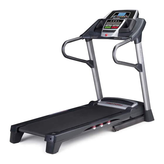
BEFORE YOU BEGIN Thank you for selecting the revolutionary PROFORM ing this manual, please see the front cover of this man- ® 1010 ZLT treadmill. The 1010 ZLT treadmill offers an ual. To help us assist you, please note the product impressive selection of features designed to make model number and serial number before contacting us. -
Page 6: Part Identification Chart
PART IDENTIFICATION CHART Use the drawings below to identify small parts used for assembly. The number in parentheses below each draw- ing is the key number of the part, from the PART LIST near the end of this manual. The number following the key number is the quantity used for assembly. -
Page 7: Assembly
ASSEMBLY • To hire a service technician to assemble this • To identify small parts, see page 6. product in your home, call 1-800-445-2480. • Assembly requires the following tools: • Assembly requires two persons. the included hex keys • Place all parts in a cleared area and remove the packing materials. - Page 8 2. Attach a Wheel (96) to the Base (95) with a 3/8" x 2" Bolt (8) and a 3/8" Nut (10). Do not over- tighten the Nut; the Wheel must turn freely. Plastic Tie Press a Base Cap (89) into the Base (95). 3.
- Page 9 4. Hold the Right Upright (85) against the Base (95). Be careful not to pinch the Upright Wire (87). Insert two 3/8" x 4" Patch Screws (7) with two 3/8" Star Washers (11) and a 3/8" x 1 1/2" Screw (14) with a 3/8" Star Washer (11) into the Right Upright.
- Page 10 6. Hold the Left Upright (84) against the Base (95). Insert two 3/8" x 4" Patch Screws (7) with two 3/8" Star Washers (11) and a 3/8" x 1 1/2" Screw (14) with a 3/8" Star Washer (11) into the Left Upright.
- Page 11 8. Remove the tie from the indicated bracket on the Right Handrail (83). If necessary, press the 5/16" Cage Nuts (38) back into place. Orient the Right Upright Cover (86) as shown, Bracket and slide it onto the Right Upright (85). Next, ori- ent a Handrail Cap (81) as shown, and slide it onto the Right Handrail (83).
- Page 12 10. IMPORTANT: To avoid damaging the Crossbar (107), do not use power tools and do not overtighten the #10 x 3/4" Screws (2). First There may be two Screws (A) in the Handrails (82, 83) in the indicated locations. If there are, remove and discard them.
- Page 13 12. Set the console assembly on the Left and Right Handrails (82, 83). Be careful not to pinch any Console Assembly wires. Attach the console assembly to the Crossbar (107) with six #8 x 3/4" Screws (1). Start all six Screws, and then tighten them.
- Page 14 14. Raise the Frame (55) to the position shown. Have a second person hold the Frame until this step is completed. Orient the Storage Latch (51) so that the large barrel and the latch knob are in the positions shown. Attach the Latch Bracket (6) and the Storage Latch (51) to the Base (95) with two 3/8"...
-
Page 15: The Chest Heart Rate Monitor
THE CHEST HEART RATE MONITOR HOW TO PUT ON THE HEART RATE MONITOR • Do not expose the heart rate monitor to direct sunlight for extended periods of time; do not expose The heart rate it to temperatures above 122° F (50° C) or below 14° monitor consists of F (-10°... -
Page 16: Operation And Adjustment
OPERATION AND ADJUSTMENT HOW TO PLUG IN THE POWER CORD Follow the steps below to plug in the power cord. This product must be earthed. If it should malfunc- 1. Plug the indicated end of the power cord into the tion or break down, earthing provides a path of least socket on the treadmill. - Page 17 CONSOLE DIAGRAM FEATURES OF THE CONSOLE You can even listen to your favorite workout music or audio books with the consoleʼs stereo sound system The treadmill console offers an impressive array of while you exercise. features designed to make your workouts more effec- To turn on the power, see page 18.
- Page 18 HOW TO TURN ON THE POWER HOW TO USE THE MANUAL MODE IMPORTANT: If the treadmill has been exposed to 1. Insert the key into the console. cold temperatures, allow it to warm to room tem- perature before you turn on the power. If you do See HOW TO TURN ON THE POWER at the left.
- Page 19 4. Change the incline of the treadmill as desired. The My Trail tab will show a track that represents 400 meters (1/4 mile). As you exercise, the flash- To change the incline of the treadmill, press the ing rectangle will show your progress. The My Trail Incline increase or decrease button or one of the tab will also show the number of laps you numbered Quick Incline buttons.
- Page 20 6. Measure your heart rate if desired. 8. When you are finished exercising, remove the key from the console. Note: If you use the handgrip heart rate monitor and the chest heart rate monitor at the same Step onto the foot rails, press the Stop button, and time, the console will not display your heart adjust the incline of the treadmill to the lowest rate accurately.
- Page 21 HOW TO USE AN ONBOARD WORKOUT During the workout, the 1. Insert the key into the console. profiles on the speed and in- See HOW TO TURN ON THE POWER on page 18. cline tabs will Current Segment show your 2.
- Page 22 HOW TO USE AN IFIT LIVE WORKOUT If the speed or incline setting is too high or too low at any time during the workout, you can manually override the setting by pressing the Speed or Note: You must have an iFit Live module to use an iFit Incline buttons;...
- Page 23 7. Measure your heart rate if desired. When you select an iFit Live workout, the display will show the duration of the workout, the distance you will walk or run, and the approximate number of See step 6 on page 20. calories you will burn.
- Page 24 THE INFORMATION MODE 3. CONTRAST LVL: Press the Incline increase and decrease buttons to adjust the contrast level of the The console features an information mode that keeps displays. Then, press the Enter button. track of treadmill information and allows you to person- If a module is connected, you may also select the alize console settings.
-
Page 25: How To Fold And Move The Treadmill
HOW TO FOLD AND MOVE THE TREADMILL HOW TO FOLD THE TREADMILL HOW TO MOVE THE TREADMILL To avoid damaging the treadmill, adjust the incline Before moving the treadmill, fold it as described at the to the lowest position before you fold the treadmill. left. -
Page 26: Troubleshooting
TROUBLESHOOTING Most treadmill problems can be solved by following SYMPTOM: The console displays remain lit when the simple steps below. Find the symptom that you remove the key from the console applies, and follow the steps listed. If further assis- tance is needed, see the front cover of this manual. - Page 27 SYMPTOM: The walking belt slows when walked on Next, remove the three #8 x 3/4" Screws (1), and carefully pivot the Motor Hood (62) off. a. If an extension cord is needed, use only a 3-con- ductor, 14-gauge (1 mm ) cord that is no longer than 5 ft.
- Page 28 SYMPTOM: The walking belt is off-center or slips b. If the walking belt slips when walked on, first re- when walked on move the key and UNPLUG THE POWER CORD. Using the hex key, turn both idler roller screws a. If the walking belt is off-center, first remove the clockwise, 1/4 of a turn.
-
Page 29: Exercise Guidelines
EXERCISE GUIDELINES WARNING: Burning Fat—To burn fat effectively, you must exer- cise at a low intensity level for a sustained period of Before beginning this time. During the first few minutes of exercise, your or any exercise program, consult your physi- body uses carbohydrate calories for energy. -
Page 30: Part List
PART LIST Model No. PETL11711.0 R0411A Key No. Qty. Description Key No. Qty. Description #8 x 3/4" Screw Storage Latch #10 x 3/4" Screw Console Ground Wire 5/16" x 1" Flat Head Patch Screw #8 x 1" Screw 5/16" x 1" Patch Bolt Right Foot Rail #8 x 1"... - Page 31 Key No. Qty. Description Key No. Qty. Description Console Grill Accent Console Frame Motor Bushing Tray Motor Isolator 5/32" Hex Key Electronics Bracket Console Clamp Filter Console Base Receptacle Crossbar Ferrite Clamp Access Door Sensor #8 x 3/4" Truss Head Screw Chest Strap #3 x 3/8"...
-
Page 32: Exploded Drawing
EXPLODED DRAWING A Model No. PETL11711.0 R0411A... - Page 33 EXPLODED DRAWING B Model No. PETL11711.0 R0411A...
- Page 34 EXPLODED DRAWING C Model No. PETL11711.0 R0411A...
- Page 35 EXPLODED DRAWING D Model No. PETL11711.0 R0411A...
-
Page 36: Ordering Replacement Parts
ORDERING REPLACEMENT PARTS To order replacement parts, see the front cover of this manual. To help us assist you, please be prepared to pro- vide the following information when contacting us: • the model number and the serial number of the product (see the front cover of this manual) •...
Need help?
Do you have a question about the PETL11711.0 and is the answer not in the manual?
Questions and answers