Heatmiser PRT User Manual
Hide thumbs
Also See for PRT:
- Operating instructions manual (27 pages) ,
- Operating instructions manual (13 pages) ,
- Operating instructions manual (33 pages)
Advertisement
Table of Contents
Advertisement
Table of Contents

Subscribe to Our Youtube Channel
Related Manuals for Heatmiser PRT


Summary of Contents for Heatmiser PRT
- Page 1 Model: PRT / PRT-N Model: PRT / PRT-N...
-
Page 2: Table Of Contents
Model: PRT / PRT-N Table of Contents Product Image Table of Contents What is a Programmable Room Thermostat? Installation Procedure LCD Display Setting the Clock Temperature Display Setting the Comfort Levels 11-12 Locking the Thermostat Setting the Temperature Temperature Hold... -
Page 3: What Is A Programmable Room Thermostat
Slimline Series Model: PRT / PRT-N... -
Page 4: Installation Procedure
Terminate the thermostat as shown in the diagrams on pages 25-29 of this booklet. Step 3 Screw the thermostat back plate securely into the back box. Step 4 Clip the front of the thermostat back onto the thermostat back plate. Slimline Series Model: PRT / PRT-N... -
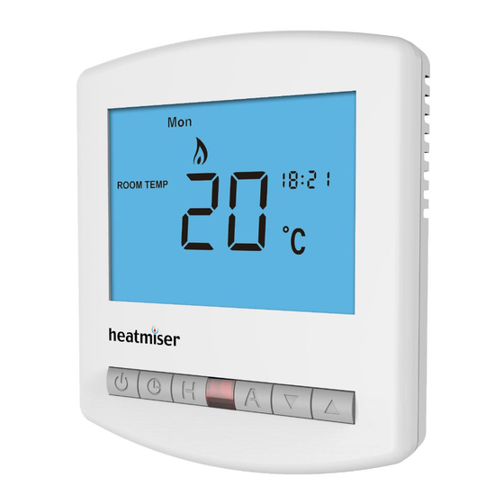
Page 5: Lcd Display
Program Cycle Indicator - Displayed during programming only to show which period is being altered. Keypad Lock Indicator - Displayed when the keypad is locked. Units of Temperature - Degrees Celsius or Fahrenheit. Clock - Digital clock display in 24h format. Slimline Series Model: PRT / PRT-N... -
Page 6: Setting The Clock
Use the Up/Down keys to set the day of the week .......... • Press A to confirm settings and return to main display .......... Hours This is the current room temperature. This is the temperature you are trying to achieve in your home. Minutes Slimline Series Model: PRT / PRT-N... -
Page 7: Comfort Levels Explained
To change the programming mode please refer to pages 20-22. For Weekday/Weekend programming, For 7 Day programming, Mon Tue Wed Thu Fri only Mon is displayed are displayed on screen. in the day indicator field. Slimline Series Model: PRT / PRT-N... -
Page 8: Locking The Thermostat
Press A to confirm settings and return to main display ..........Note: The keypad lock indicator is only displayed when the lock is active. Note: This override will be maintained until the next programmed comfort level. Set Temperature Set Icon Keypad Lock Indicator Slimline Series Model: PRT / PRT-N... -
Page 9: Temperature Hold
Holiday Days Holiday ON Indicator To cancel, follow the same steps but reduce the Holiday duration to 00 days. To cancel temperature hold, follow the same steps but reduce the Hold time to 00:00 hours. Slimline Series Model: PRT / PRT-N... -
Page 10: Frost Mode
To turn the thermostat back ON, press the Power button once again ....To cancel the frost protect mode, press the Power button once again. Thermostat powered ON Thermostat completely OFF Frost Protection Mode Enabled *See Feature 3 on page 19 Slimline Series Model: PRT / PRT-N... - Page 11 4 different comfort levels for the weekend. In 7 Day program mode, each day has 4 your thermostat to a network system. Each thermostat on your network must have a comfort levels that can be programmed independently. unique communication address. This can be set from 01-32. Slimline Series Model: PRT / PRT-N...
-
Page 12: Frost Protection
• Use the Up/Down keys to change the setting ............ (00 = Default) • Press A to confirm settings ....................• Press the Power button once again to turn the thermostat back ON ....Slimline Series Model: PRT / PRT-N... -
Page 13: Re-Calibrating The Thermostat
Press the Power button once to turn the thermostat back ON ......been successfully reset. • Press the Power button once to turn the thermostat back ON ......All icons displayed simultaneously. Factory reset is complete. Calibration Temperature Setting Set Icon Slimline Series Model: PRT / PRT-N... - Page 14 Wiring Diagram - PRT to Boiler S/L Wiring Diagram - PRT to Boiler Voltfree THIS UNIT MUST BE PROTECTED BY A FUSE OR RCD THIS UNIT MUST BE PROTECTED BY A FUSE OR RCD 230V AC 50/60Hz 230V AC 50/60Hz...
- Page 15 Wiring Diagram - PRT to Valve Wiring Diagram - PRT-N to PRC Volt Free Switching Voltfree Switching With the Heatmiser PRC PRT-N THIS UNIT MUST BE PROTECTED BY A FUSE OR RCD Recommendations 12VDC Max Cable Size - 1.5MM Network...
- Page 16 Notes Wiring Diagram - PRT-N to UH1 ..................................PRT-N ..................................Connecting PRT-N to the UH1 12VDC ..................................Network The UH1 allows connection of up to eight 12 volt network thermostats..................................When connecting network thermostats to the UH1 use CAT5-FTP or BELDEN 9538.
- Page 17 Heating Professionals: Request a copy of our product installation guide containing detailed technical specifications for our complete product range: www.heatmiser.com/guide Want More Information? Call our support team on: +44 (0)1254 669090 Or view technical specifications directly on our website: www.heatmiser.com...
Need help?
Do you have a question about the PRT and is the answer not in the manual?
Questions and answers