Table of Contents
Advertisement
Quick Links
Advertisement
Table of Contents

Related Manuals for Contex Wide Format Color


Summary of Contents for Contex Wide Format Color
- Page 1 Operator’s Guide Wide Format Color & Monochrome Scanners...
-
Page 2: Table Of Contents
Table of Contents 1. About This Guide 2. Scanner System Requirements 3. Installation 3.1 Set up the scan station 3.2 Smart Card 3.3 Install Drivers and Maintenance software 3.4 Select the Scanner Interface 3.4.1 Interface Types 3.4.2 Cable Connector Panel on the Scanner 3.5 Connection through the FireWire interface 3.5.1 Check your computer for FireWire... - Page 3 7. Appendix A: Important Safety Instructions 8. Appendix B: Regulations...
-
Page 4: About This Guide
About This Guide 1. About This Guide This guide explains how to operate and maintain your wide format scanner. The operator’s guide is general and covers several scanner models, although there are specific individual features between the different models. Therefore, you should view the scanner specifications for your particular model if you are unsure whether a feature described in this guide is relevant for your specific scanner. -
Page 5: Scanner System Requirements
System Requirements 2. Scanner System Requirements • PC or supported workstation. • Compatible Windows operating system - see the WIDEsystem TOOLS documentation for details." • USB port, enabled FireWire Port, or an SCSI interface-kit matching your workstation. (Note: USB and FireWire are not supported on Windows NT) •... -
Page 6: Installation
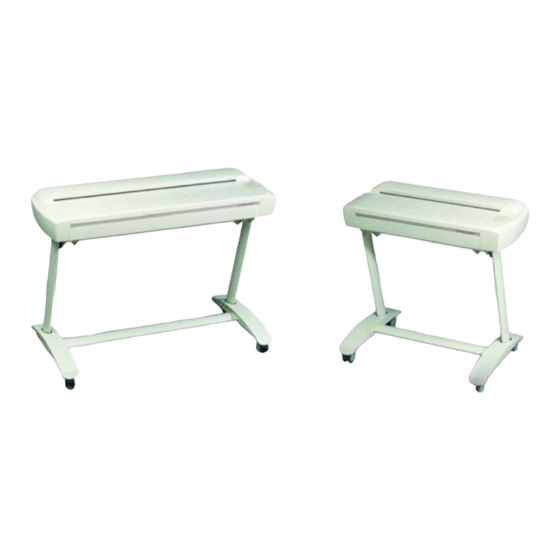
Installation 3. Installation 3.1 Set up the scan station Your wide format scanner should be placed either on a sturdy table or the specially designed stand-alone floor stand. The 25” models are small enough to place on your desk. Make sure there is enough space behind the scanner to allow the media to run out. -
Page 7: Select The Scanner Interface
Installation 3.4 Select the Scanner Interface Different scanner models support specific types of interface connections. On some scanners, two different types of interfaces can be used and you need to select the one that is best for your scanning purposes and is compatible with your PC system. The Interface types and their advantages are described in the following section. -
Page 8: Cable Connector Panel On The Scanner
Installation 3.4.2 Cable Connector Panel on the Scanner The interface cable connectors are grouped in a Cable-Connector- Panel found on the underside of the scanner and accessed from the scanner’s back. As illustrated in the interface table above, the different scanner models support different options for interfacing. - Page 9 Installation USB + SCSI Cable - Connectors SCSI connectors (One for connection to PC and one for daisy-chaining another device) (Future purpose connector) USB connector Figure 3-2 Scanner USB and SCSI Connectors on Cougar Scanners Note: The extra SCSI connector is only used if you wish to daisy- chain another device to your system and not for interfacing with another PC.
- Page 10 Installation FireWire + SCSI Cable - Connectors SCSI connectors (One for connection to PC and one for daisy-chaining another device) (Future purpose connector) FIREWIRE FIREWIRE FireWire connectors Figure 3-3 FireWire + SCSI Connector Note: The extra SCSI connector and extra FireWire connector are for daisy-chaining another device to your system and not for interfacing with another PC.
-
Page 11: Connection Through The Firewire Interface
Installation 3.5 Connection through the FireWire interface To connect through FireWire, you will need the FireWire cable that came with your scanner and your computer must be enabled for FireWire through a FireWire card and port. FireWire is not supported on Windows NT. -
Page 12: Connection Through The Usb Interface
Installation 6. Follow the installation instructions in the WIDEsystem TOOLS User’s Guide that came on the WIDEsystem TOOLS CD. The scanner drivers are installed through an installation wizard. 3.5.3 “Unknown device is found” message If your system has problems detecting the scanner, make sure your FireWire port is enabled (see above). - Page 13 Installation 3.6.2 Connect the scanner with the USB cable 1. Locate the USB cable that came with your scanner. 2. Connect the PC end to a USB port on your computer 3. Connect the peripheral end to the USB connection socket on your scanner.
-
Page 14: Connection Through The Scsi Interface
Installation 3.7 Connection through the SCSI interface SCSI stands for Small Computer System Interface and is pronounced "skuzzy". It's a standard for connecting peripherals to your computer via a standard hardware interface, which uses standard SCSI commands. Your SCSI interface supports the Ultra SCSI (8-bit Narrow) SCSI type interface. - Page 15 Installation 3-10 3.7.2 Step 2: Install the SCSI driver software SCSI driver installation will be dependent on your Windows operating system. Follow the instructions for your operating system described in the SCSI driver documentation. 3.7.3 Step 3: Connect the scanner to the PC 1.
- Page 16 Installation 3-11 You will find the DIL-switches in the small Smart Card drawer labeled “PUSH” behind the scanner front streamer. To access the switches remove the streamer, push the drawer inwards and release so it pops open and remove the Smart Card. Figure 3-4 Access the DIL-switches Important: Remember to reinsert the Smart Card when finished setting the DIL-switches and before turning power on.
- Page 17 Installation 3-12 Device number setup – switch 1,2,3 Make sure the power to the computer and the scanner are OFF when setting the SCSI device number, as the switch settings are only read from the scanner DIL-switch during the scanner’s power up. You can set up the SCSI device no.
- Page 18 Installation 3-13 The following 3 scenarios show how to terminate the SCSI bus correctly: A. The Scanner is the only external device on the SCSI bus Switch 4 must be ON SCSI SCANNER Host Computer B. The Scanner is the last device on the SCSI bus Switch 4 must be ON SCSI SCSI...
- Page 19 Installation 3-14 Troubleshooting and Test Controls – switches 5, 6, 7 and 8 Switch 5. No synchronous transfer: Disables SCSI synchronous transfer mode (reverts to asynchronous transfer). Only use this mode for testing as it slows the scanner down. Switch 6. Not in use – no effect. Switch 7.
-
Page 20: Installation Verification
Installation 3-15 3.8 Installation Verification Turn on the power to the computer and the scanner. If you have not yet done so, install the Scanner Maintenance Software and your scanning applications on your PC. Follow the installation instructions supplied with each item. The Scanner Maintenance Software is on your WIDEsystem TOOLS CD. -
Page 21: Operator Panel And Indicators
Operator Panel and Indicators 4. Operator Panel and Indicators The Scanner Operator Panel is divided into 3 areas: A Scanner control area with 1 key and 3 LED indicators. An Application control area with 3 keys. A Paper control area with 2 keys and 1 LED indicator. On some scanner models, an Automatic Thickness Adjustment Control (ATAC) key is also available in the Paper control area. - Page 22 Operator Panel and Indicators Operator’s Panel with ATAC (Automatic Thickness Adjustment Control) functionality - Detailed descriptions of each numbered item follow in the next sections. Scanner Control area: Application Control area: Paper Control area:...
-
Page 23: Scanner Control Area
Operator Panel and Indicators 4.1 Scanner Control area 1. Power switch and power LED When you connect the scanner to the power outlet and turn on the outlet switch at the back of the scanner, it starts up in ON mode meaning it boots and the LED lights green. - Page 24 Operator Panel and Indicators 3. Wait LED The Wait LED lights when the scanner power is turned on, and stays on during the internal diagnostic and stabilization phase. Keyboard input is prevented during this time. The Wait indicator reveals the status of the scanner’s self-adjustment procedure, which consists of both stitching and light profile adjustment.
-
Page 25: Application Control Area
Operator Panel and Indicators 4.2 Application Control Area The following buttons require correct installation of the WIDEsystem TOOLS CD, software application components and setup definitions before they can become active. Your scanner must be running through STI (Still Image Interface) on Windows and your PC must be turned on and running. -
Page 26: Paper Control Area
Operator Panel and Indicators 4.3 Paper Control area Use the Paper Control area when you insert your document. 7. Paper Forward and Paper Reverse Key The Paper Forward Key moves the drawing into the start-of-scan position. • If the Auto-Load option is selected in your scan application, loading will take place automatically as soon as the original enters the insertion slot. - Page 27 Operator Panel and Indicators • The Paper Ready indicator stays ON, signifying that the scanner is ready to be controlled from the computer. • During scanning the Ready indicator will blink. • At end of scanning the Ready indicator will stop blinking signifying that scanning can be repeated from the computer, or else terminated by ejecting the original from the scanner.
-
Page 28: Original's Insertion Slot
Insertion Slot 5. Original’s Insertion Slot 5.1 Rulers The Original’s Insertion slot (picture below) is marked with a measurement ruler for inches and millimeters. The ruler corresponds to right side aligned original loading. Just below the ruler are marked common standard sizes that help guide you with optional centered loading. -
Page 29: Scanning Thick Media
Insertion Slot 5.2 Scanning Thick Media Scanning needs are not always limited to convenient paper-thin media. Many industries, such as reprographics and GIS, will find the need to digitize or copy images printed or pasted on thicker media such as cardboard, foamboards, gatorboards etc. To support such needs you can change the vertical size of the insertion slot (guide plate height) on your scanner so you can fit the slot to the thickness of your original. - Page 30 Insertion Slot The media thickness can be set in the following steps (corresponding to the indications on the right and left adjustment sliders): Step MaximumThickness 2mm (0.08”) (Normal Position) 4mm (0.16”) 6mm (0.24”) 8mm (0.32”) 10mm (039”) 12mm (0.47”) 14mm (0.55”) 15mm (0.60”) Measure the thickness of your original to find the right setting.
- Page 31 Insertion Slot 3. Press and hold the Paper Forward key (arrow up) key to raise the guide plate until there is room to insert the thick original. 4. Insert the thick original evenly for a straight scan path. 5. Press and hold the Paper Reverse (arrow down) key to lower the guide plate until the guide plate stops on its own.
-
Page 32: Accessing The Scan Area
Insertion Slot Treating Edge Distortion Scanning thick originals can give distortions when the front edge meets the exit rollers or the trailing edge leaves the entry rollers. To omit this, the leading and trailing edges are by default skipped when in one of the extended media thickness positions. -
Page 33: Changing The Glass Plate
Insertion Slot Figure 5-3 Slider in the exit position 5.3.2 Flip Open the Pressure Platen – ATAC models The following applies only for scanner models with Automatic Thickness Adjustment Control (ATAC) functionality. 1. Push down on the two lever buttons found near the insertion slot on each side of the scanner’s top cover. -
Page 34: Insertion Slot
Insertion Slot 3. On each side of the glass plate there is a small lever and round finger-handle. With both arms, pull the left and right levers backwards to flip the glass plate upwards towards your body. 4. The levers are attached to the scanner chassis with a small hook. Lift the levers out of the hook to free the glass plate from the scanner. -
Page 35: Maintenance
Maintenance 6. Maintenance Regular scanner maintenance is a sure way to minimize costly downtime. The Automatic Scanner Maintenance system supported on your scanner hinders your scanner from degrading over time. The three routine maintenance procedures cleaning, camera alignment and calibration will improve image quality and reduce your service costs. - Page 36 A: Safety Instructions 7. Appendix A: Important Safety Instructions Read all of these instructions and save instructions for later use. Follow all warnings and instructions marked on the scanner. A. Do not place the scanner on an unstable surface, stand, cart or table.
- Page 37 A: Safety Instructions that could result in a risk of fire or electrical shock. Avoid any possibility of spilling liquid of any kind on the scanner. I. Do not attempt to service the scanner yourself. Opening or removing those covers requiring tools may expose you to dangerous voltage points or other risks.
- Page 38 B: Regulations 8. Appendix B: Regulations FCC Regulations This equipment has been tested and found to comply with the limits for a class A digital device, pursuant to Part 15 of the FCC Rules. These limits are designed to provide reasonable protection against harmful interference when the equipment is operated in a commercial environment.
Need help?
Do you have a question about the Wide Format Color and is the answer not in the manual?
Questions and answers