Table of Contents

Related Manuals for IEI Technology KINO-GM45A


Summary of Contents for IEI Technology KINO-GM45A
-
Page 1: User Manual
KINO-GM45A Mini-ITX SBC KINO-GM45A CPU Card IEI Technology Corp. MODEL: KINO-GM45A Mini-ITX Motherboard Supports Intel® Core™2 Duo CPU, VGA/LVDS/HDTV-out, GbE, USB 2.0 and Two SATA II User Manual Page I Rev. 1.00 - 11 January, 2010... - Page 2 KINO-GM45A Mini-ITX SBC Revision Date Version Changes 11 January, 2010 1.00 Initial release Page II...
- Page 3 KINO-GM45A Mini-ITX SBC Copyright COPYRIGHT NOTICE The information in this document is subject to change without prior notice in order to improve reliability, design and function and does not represent a commitment on the part of the manufacturer. In no event will the manufacturer be liable for direct, indirect, special, incidental, or consequential damages arising out of the use or inability to use the product or documentation, even if advised of the possibility of such damages.
-
Page 4: Table Of Contents
ACKING 2.3.1 Optional Items....................12 3 CONNECTORS ......................14 3.1 P ..............15 ERIPHERAL NTERFACE ONNECTORS 3.1.1 KINO-GM45A Layout ..................15 3.1.2 Peripheral Interface Connectors ..............16 3.1.3 External Interface Panel Connectors............... 17 3.2 I ..............18 NTERNAL ERIPHERAL ONNECTORS 3.2.1 Audio Connector .................... - Page 5 KINO-GM45A Mini-ITX SBC 3.2.11 12V Power Connector ..................29 3.2.12 SATA Drive Connectors ................. 30 3.2.13 SATA Power Connector.................. 31 3.2.14 Serial Port Connector (RS-232/422/485) ............31 3.2.15 Serial Port Connectors (RS-232) ..............32 3.2.16 SPDIF Connector................... 33 3.2.17 SPI Flash Connector..................34 3.2.18 USB Connectors.....................
- Page 6 KINO-GM45A Mini-ITX SBC 4.7.1 Audio Kit Installation..................57 4.7.2 Keyboard/Mouse Connector ................58 4.7.3 Dual RS-232 Cable with Slot Bracket.............. 60 4.8 E ........... 61 XTERNAL ERIPHERAL NTERFACE ONNECTION 4.8.1 LAN Connection (Single Connector) ............... 61 4.8.2 USB Connection (Dual Connector) ..............62 4.8.3 VGA Monitor Connection ................
- Page 7 KINO-GM45A Mini-ITX SBC 5.7.2 Southbridge Configuration ................100 5.8 E ........................101 A BIOS MENU OPTIONS ................... 103 B TERMINOLOGY...................... 106 C WATCHDOG TIMER ....................111 D HAZARDOUS MATERIALS DISCLOSURE ............114 D.1 H IPB P AZARDOUS ATERIAL ISCLOSURE ABLE FOR RODUCTS...
- Page 8 Figure 3-17: SPDIF Connector Location ..................34 Figure 3-18: SPI Flash Connector ....................35 Figure 3-19: USB Connector Pinout Locations .................36 Figure 3-20: KINO-GM45A External Peripheral Interface Connector ........37 Figure 3-21: RJ-45 Ethernet Connector..................38 Figure 3-22: VGA Connector .......................40 Figure 4-1: Make sure the CPU socket retention screw is unlocked ........47 Figure 4-2: Lock the CPU Socket Retention Screw..............48...
- Page 9 KINO-GM45A Mini-ITX SBC Figure 4-5: Jumper Locations .....................50 Figure 4-6: AT Power Select Jumper Location................52 Figure 4-7: Clear CMOS Jumper ....................53 Figure 4-8: COM 2 Function Select Jumper Location...............54 Figure 4-9: LVDS Panel Resolution Jumper Pinout Locations..........55 Figure 4-10: LVDS Voltage Selection Jumper Pinout Locations ..........56 Figure 4-11: Audio Kit Cable Connection ..................58...
- Page 10 KINO-GM45A Mini-ITX SBC List of Tables Table 1-1: Technical Specifications....................8 Table 3-1: Peripheral Interface Connectors ................17 Table 3-2: Rear Panel Connectors ....................17 Table 3-3: Audio Connector Pinouts ..................18 Table 3-4: Panel Backlight Connector Pinouts................19 Table 3-5: Digital I/O Connector Pinouts..................20 Table 3-6: CPU Fan Connector Pinouts..................21...
- Page 11 KINO-GM45A Mini-ITX SBC Table 4-5: LVDS Panel Resolution Jumper Settings..............55 Table 4-6: LVDS Voltage Selection Jumper Settings..............56 Table 5-1: BIOS Navigation Keys ....................69 Page XI...
-
Page 12: Figure 1-1: Kino-Gm45A
KINO-GM45A Mini-ITX SBC List of BIOS Menus BIOS Menu 1: Main ........................70 BIOS Menu 2: Advanced ......................72 BIOS Menu 3: CPU Configuration ....................72 BIOS Menu 4: IDE Configuration....................73 BIOS Menu 5: IDE Master and IDE Slave Configuration ............75 BIOS Menu 6: Super IO Configuration..................79 BIOS Menu 7: Hardware Health Configuration ................82... -
Page 13: Introduction
KINO-GM45A Mini-ITX SBC Chapter Introduction Page 1... -
Page 14: Introduction
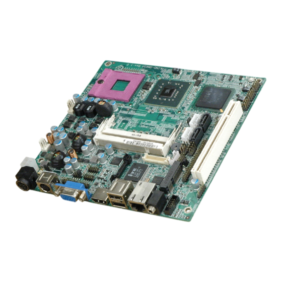
KINO-GM45A Mini-ITX SBC 1.1 Introduction Figure 1-1: KINO-GM45A The KINO-GM45A Mini-ITX motherboard is a Socket P 45nm Intel® Core™2 Duo processor (Penryn) platform. Up to two 2.0 GB 667 MHz or 800 MHz DDR2 SDRAM SO-DIMM are supported by the Intel®... -
Page 15: Connectors
KINO-GM45A Mini-ITX SBC 1.2 Connectors The connectors on the KINO-GM45A are shown in the figure below. Figure 1-2: Connectors Page 3... -
Page 16: Dimensions
KINO-GM45A Mini-ITX SBC 1.3 Dimensions 1.3.1 Board Dimensions The dimensions of the board are listed below: Length: 170 mm Width: 170 mm Figure 1-3: KINO-GM45A Dimensions (mm) Page 4... -
Page 17: External Interface Panel Dimensions
KINO-GM45A Mini-ITX SBC 1.3.2 External Interface Panel Dimensions External peripheral interface connector panel dimensions are shown in F igure 1-4. Figure 1-4: External Interface Panel Dimensions (mm) Page 5... -
Page 18: Data Flow
KINO-GM45A Mini-ITX SBC 1.4 Data Flow F igure 1-5 shows the data flow between the two on-board chipsets and other components installed on the motherboard and described in the following sections of this chapter. Figure 1-5: Data Flow Block Diagram... -
Page 19: Technical Specifications
KINO-GM45A Mini-ITX SBC 1.5 Technical Specifications KINO-GM45A technical specifications are listed in table below. Specification KINO-GM45A Mini-ITX Form Factor Socket P Socket 45 nm Socket P Intel® Core™2 Duo processor CPU Supported Front Side Bus (FSB) 1066 MHz (Max.), 800 MHz or 667 MHz Northbridge Chipset Intel®... -
Page 20: Table 1-1: Technical Specifications
KINO-GM45A Mini-ITX SBC Specification KINO-GM45A Display Ports One VGA port One 18-bit or 24-bit dual-channel LVDS port One TV-out port supports HDTV One external HDMI port supports up to 1080p Ethernet One RJ-45 GbE port Three RS-232 via three 10-pin header connectors... -
Page 21: Unpacking
KINO-GM45A Mini-ITX SBC Chapter Unpacking Page 9... -
Page 22: Anti-Static Precautions
Only handle the edges of the PCB: Don't touch the surface of the motherboard. Hold the motherboard by the edges when handling. 2.2 Unpacking Precautions When the KINO-GM45A is unpacked, please do the following: Follow the antistatic guidelines above. Make sure the packing box is facing upwards when opening. -
Page 23: Packing List
If any of the components listed in the checklist below are missing, do not proceed with the installation. Contact the IEI reseller or vendor the KINO-GM45A was purchased from or contact an IEI sales representative directly by sending an email to ales@iei.com.tw. -
Page 24: Optional Items
KINO-GM45A Mini-ITX SBC Utility CD Quick Installation Guide 2.3.1 Optional Items The KINO-GM45A is shipped with the following components: Item and Part Number Image CPU cooler (P/N: CF-479B-RS) Dual USB cable (with bracket) (P/N: CB-USB02-RS) SATA power cable (P/N: 32100-088600-RS) - Page 25 KINO-GM45A Mini-ITX SBC PCIe Mini wireless LAN card 802.11b/g (P/N: WMUSB-V01-RS) PCIe Mini wireless LAN card 802.11b/g (P/N: WMPCIE-V01-RS) PCIe/USB mini card expansion module (P/N: IO-KIT-MPCIE-R10) SATA to IDE/CF converter board (P/N: SAIDE-KIT01-RS) 96W 12V power adapter (90 VAC~260 VAC, 4-pin DIN)
-
Page 26: Connectors
KINO-GM45A Mini-ITX SBC Chapter Connectors Page 14... -
Page 27: Peripheral Interface Connectors
KINO-GM45A Mini-ITX SBC 3.1 Peripheral Interface Connectors This chapter details all the jumpers and connectors. 3.1.1 KINO-GM45A Layout The figures below show all the connectors and jumpers. Figure 3-1: Connector and Jumper Locations Page 15... -
Page 28: Peripheral Interface Connectors
KINO-GM45A Mini-ITX SBC 3.1.2 Peripheral Interface Connectors The table below lists all the connectors on the board. Connector Type Label Audio connector 10-pin box header AUDIO1 Battery connector 2-pin wafer BAT1 Backlight inverter 12 V power connector 5-pin wafer INVERTER1... -
Page 29: External Interface Panel Connectors
KINO-GM45A Mini-ITX SBC Serial ATA (SATA) drive connector 7-pin SATA S_ATA2 SATA power connector 4-pin wafer SATA power connector 4-pin wafer SPDIF connector 5-pin header SPDIF1 SPI Flash connector 8-pin header JSPI1 USB connector (1) 8-pin header USB23 USB connector (2) -
Page 30: Internal Peripheral Connectors
KINO-GM45A Mini-ITX SBC 3.2 Internal Peripheral Connectors The section describes all of the connectors on the KINO-GM45A. 3.2.1 Audio Connector CN Label: AUDIO1 CN Type: 10-pin box header (2x5) CN Location: See Figure 3-2 CN Pinouts: See Table 3-3 The audio connector is connected to external audio devices including speakers and microphones for the input and output of audio signals to and from the system. -
Page 31: Backlight Inverter Connector
See Figure 3-3 CN Pinouts: See Table 3-4 The backlight inverter connector provides the backlight on the LCD display connected to the KINO-GM45A with +12V of power. Figure 3-3: Panel Backlight Connector Pinout Locations PIN NO. DESCRIPTION LCD Backlight Control... -
Page 32: Fan Connector (Cpu)
KINO-GM45A Mini-ITX SBC The digital I/O connector provides programmable input and output for external devices. The digital I/O provides 4-bit output and 4-bit input. Figure 3-4: Digital I/O Connector Locations Description Description Output 3 Output 2 Output 1 Output 0... -
Page 33: Fan Connector (System)
KINO-GM45A Mini-ITX SBC Figure 3-5: CPU Fan Connector Location Description GROUND +12V CPUFANIN CPUFANOUT Table 3-6: CPU Fan Connector Pinouts 3.2.5 Fan Connector (System) CN Label: FAN1 CN Type: 3-pin wafer (1x3) CN Location: F igure 3-6 CN Pinouts: T able 3-7 The cooling fan connector provides a 12V, 500mA current to the cooling fan. -
Page 34: Front Panel Connector
KINO-GM45A Mini-ITX SBC Figure 3-6: +12V Fan Connector Locations PIN NO. DESCRIPTION SYSFANIN0 +12V Table 3-7: +12V Fan Connector Pinouts 3.2.6 Front Panel Connector CN Label: F_PANEL1 CN Type: 8-pin header (2x4) CN Location: See Figure 3-7 CN Pinouts: See Table 3-8 The front panel connector connects to external switches and indicators to monitor and controls the motherboard. -
Page 35: Keyboard/Mouse Connector
KINO-GM45A Mini-ITX SBC Figure 3-7: Front Panel Connector Location FUNCTION DESCRIPTION FUNCTION DESCRIPTION Power Button PWRBTSW- Power LED +V5S GROUND GROUND HDD LED +V5S Reset SYSRST- -HDLED GROUND Table 3-8: Front Panel Connector Pinouts 3.2.7 Keyboard/Mouse Connector CN Label: KB_MS1... -
Page 36: Lvds Lcd Connector
KINO-GM45A Mini-ITX SBC Figure 3-8: Keyboard/Mouse Connector Location Description +5 VCC MS DATA MS CLK KB DATA KB CLK GROUND Table 3-9: Keyboard/Mouse Connector Pinouts 3.2.8 LVDS LCD Connector CN Label: LVDS1 CN Type: 30-pin crimp (2x15) CN Location: F igure 3-9... -
Page 37: Figure 3-9: Lvds Lcd Connector Pinout Location
KINO-GM45A Mini-ITX SBC Figure 3-9: LVDS LCD Connector Pinout Location PIN NO. DESCRIPTION PIN NO. DESCRIPTION GND1 GND2 A_Y0 A_Y0# A_Y1 A_Y1# A_Y2 A_Y2# A_CK A_CK# A_Y3 A_Y3# GND3 GND4 B_Y0 B_Y0# B_Y1 B_Y1# B_Y2 B_Y2# B_CK B_CK# B_Y3 B_Y3#... -
Page 38: Pcie Mini Card Slot
KINO-GM45A Mini-ITX SBC 3.2.9 PCIe Mini Card Slot CN Label: 52-pin PCIe Mini Card Slot CN Type: CN Location: F igure 3-10 CN Pinouts: See Table 3-11 The PCIe mini card slot enables a PCIe mini card expansion module to be connected to the board. -
Page 39: Pcie Mini Card Expansion Connector
KINO-GM45A Mini-ITX SBC PCIRST# PERN2 3VDual PERP2 1.5V SMBCLK PETN2 SMBDATA PETP2 USBD- USBD+ 1.5V 3.3V Table 3-11: PCIe Mini Card Slot Pinouts 3.2.10 PCIe Mini Card Expansion Connector CN Label: CN Type: 48-pin header (2x24) CN Location: F igure 3-10... -
Page 40: Figure 3-11: Pcie Mini Card Expansion Connector Location
KINO-GM45A Mini-ITX SBC Figure 3-11: PCIe Mini Card Expansion Connector Location Description Description PCIE_TXP1 PCIE_TXP2 PCIE_TXN1 PCIE_TXN2 PCIE_RXP1 PCIE_RXP2 PCIE_RXN1 PCIE_RXN2 CLK_PCIE_MINI_1 CLK_PCIE_MINI_2 CLK_PCIE_MINI_1# CLK_PCIE_MINI_2# USB_PP8 USB_PP9 USB_PN8 USB_PN9 MINICARD_CLKREQ1# MINICARD_CLKREQ2# PM_GPIO_RF_OFF1# PM_GPIO_RF_OFF2# SMBDATA +V3.3A SMBCLK +V3.3A Page 28... -
Page 41: Power Connector
KINO-GM45A Mini-ITX SBC Description Description PCIRST3- PCIE_WAKE# +V1.5S +V3.3S +V1.5S +V3.3S +V1.5S +V3.3S Table 3-12: PCIe Mini Card Expansion Connector Pinouts 3.2.11 12V Power Connector CN Label: PWR2 CN Type: 4-pin Molex power connector (1x4) CN Location: See Figure 3-12... -
Page 42: Sata Drive Connectors
KINO-GM45A Mini-ITX SBC 3.2.12 SATA Drive Connectors CN Label: S_ATA1 and S_ATA2 CN Type: 7-pin SATA drive connectors CN Location: F igure 3-13 CN Pinouts: T able 3-14 The two SATA II drive connectors are each connected to a SATA II drive. The SATA II drives transfer data at speeds as high as 3.0 Gb/s. -
Page 43: Sata Power Connector
KINO-GM45A Mini-ITX SBC 3.2.13 SATA Power Connector CN Label: CN6 and CN7 CN Type: 4-pin wafer (1x4) CN Location: See Figure 3-14 CN Pinouts: See Table 3-15 The SATA Power Connector provides +5V and +12V power output to the SATA connector. -
Page 44: Serial Port Connectors (Rs-232)
KINO-GM45A Mini-ITX SBC Used for RS-232/422/485 communications. Figure 3-15: Serial Port Connector Location PIN NO. DESCRIPTION PIN NO. DESCRIPTION TXD485+ TXD485# RXD485+ RXD485# Table 3-16: Serial Port Connector Pinouts 3.2.15 Serial Port Connectors (RS-232) CN Label: COM1, COM3 and COM4... -
Page 45: Spdif Connector
KINO-GM45A Mini-ITX SBC Figure 3-16: COM Connector Pinout Locations PIN NO. DESCRIPTION PIN NO. DESCRIPTION Data Carrier Direct (DCD) Data Set Ready (DSR) Receive Data (RXD) Request To Send (RTS) Transmit Data (TXD) Clear To Send (CTS) Data Terminal Ready (DTR) -
Page 46: Spi Flash Connector
KINO-GM45A Mini-ITX SBC Figure 3-17: SPDIF Connector Location DESCRIPTION SPDIF OUT SPDIF IN Table 3-18: SPDIF Connector Pinouts 3.2.17 SPI Flash Connector CN Label: JSPI1 CN Type: 8-pin header (2x4) CN Location: See Figure 3-18 CN Pinouts: See Table 3-19 The 6-pin SPI Flash connector is used to flash the BIOS. -
Page 47: Usb Connectors
KINO-GM45A Mini-ITX SBC Figure 3-18: SPI Flash Connector DESCRIPTION DESCRIPTION SPI_VCC SPI_CS SPI_CLK SPI_SO SPI_SI Table 3-19: SPI Flash Connector 3.2.18 USB Connectors CN Label: USB23, USB45 and USB67 CN Type: 8-pin header (2x4) See Figure 3-19 CN Location: CN Pinouts: See Table 3-25 The USB connectors connect to USB devices. -
Page 48: External Peripheral Interface Connector Panel
DATA- Table 3-20: USB Port Connector Pinouts 3.3 External Peripheral Interface Connector Panel F igure 3-20 shows the KINO-GM45A external peripheral interface connector (EPIC) panel. The KINO-GM45A EPIC panel consists of the following: 1 x Audio speaker-out jack 1 x Ethernet connector... -
Page 49: Audio Connector
CN Type: RJ-45 CN Location: F igure 3-20 CN Pinouts: T able 3-21 The KINO-GM45A is equipped with one built-in RJ-45 Ethernet controller. The controller can connect to the LAN through one RJ-45 LAN connector. DESCRIPTION DESCRIPTION MDIA3- MDIA1+ MDIA3+... -
Page 50: Hdmi Connector
KINO-GM45A Mini-ITX SBC Figure 3-21: RJ-45 Ethernet Connector The RJ-45 Ethernet connector has two status LEDs, one green and one yellow. The green LED indicates activity on the port and the yellow LED indicates the port is linked. See T able 3-22. -
Page 51: Tv Connector
KINO-GM45A Mini-ITX SBC HDMI_DATA0 HDMI_HPD HDMI_GND HDMI_DATA0# HDMI_GND HDMI_CLK HDMI_GND HDMI_GND HDMI_CLK# Table 3-23: HDMI Connector Pinouts 3.3.4 TV Connector CN Label: 7-pin Mini-DIN CN Type: CN Location: See Figure 3-20 CN Pinouts: See Table 3-24 A 7-pin mini DIN connector is located on the mounting bracket for easy connection to a TV OUT cable. -
Page 52: Vga Connector
KINO-GM45A Mini-ITX SBC CN Location: F igure 3-20 CN Pinouts: T able 3-25 The KINO-GM45A has two external USB 2.0 ports. The ports connect to both USB 2.0 and USB 1.1 devices. PIN NO. DESCRIPTION PIN NO. DESCRIPTION DATA- DATA-... -
Page 53: Table 3-26: Vga Connector Pinouts
KINO-GM45A Mini-ITX SBC DESCRIPTION DESCRIPTION VGAVCC GREEN GROUND BLUE DDCDAT GROUND HSYNC CRT_PLUG# VSYNC GROUND DDCCLK GROUND Table 3-26: VGA Connector Pinouts Page 41... -
Page 54: Installation
KINO-GM45A Mini-ITX SBC Chapter Installation Page 42... -
Page 55: Anti-Static Precautions
Electrostatic discharge (ESD) can cause serious damage to electronic components, including the KINO-GM45A. Dry climates are especially susceptible to ESD. It is therefore critical that whenever the KINO-GM45A, or any other electrical component is handled, the following anti-static precautions are strictly adhered to. -
Page 56: Installation Considerations
KINO-GM45A is installed. All installation notices pertaining to the installation of the KINO-GM45A should be strictly adhered to. Failing to adhere to these precautions may lead to severe damage of the KINO-GM45A and injury to the person installing the motherboard. 4.2.1 Installation Notices... -
Page 57: Unpacking
4.3 Unpacking When the KINO-GM45A is unpacked, please check all the unpacking list items listed in Chapter 3 are indeed present. If any of the unpacking list items are not available please contact the KINO-GM45A vendor reseller/vendor where the KINO-GM45A was purchased or contact an IEI sales representative. -
Page 58: Socket P Cpu Installation
To install a socket P CPU onto the KINO-GM45A, follow the steps below: WARNING: When handling the CPU, only hold it on the sides. DO NOT touch the pins at the bottom of the CPU. -
Page 59: Figure 4-1: Make Sure The Cpu Socket Retention Screw Is Unlocked
KINO-GM45A Mini-ITX SBC Figure 4-1: Make sure the CPU socket retention screw is unlocked Step 2: Inspect the CPU socket. Make sure there are no bent pins and make sure the socket contacts are free of foreign material. If any debris is found, remove it with compressed air. -
Page 60: Socket P Cooling Kit Installation
KINO-GM45A Mini-ITX SBC Figure 4-2: Lock the CPU Socket Retention Screw 4.4.2 Socket P Cooling Kit Installation An IEI Socket P CPU cooling kit can be purchased separately. (See Chapter 3) The cooling kit comprises a CPU heat sink and a cooling fan. -
Page 61: Figure 4-3: Cooling Kit Support Bracket
Make sure the hooks are properly secured to the bracket. To secure the cooling kit, close the top lever. Step 4: Connect the fan cable. Connect the cooling kit fan cable to the fan connector on the KINO-GM45A. Carefully route the cable and avoid heat generating chips and fan blades.Step 0: Page 49... -
Page 62: So-Dimm Installation
KINO-GM45A Mini-ITX SBC 4.4.3 SO-DIMM Installation To install an SO-DIMM, please follow the steps below and refer to Figure 4-4. Figure 4-4: SO-DIMM Installation Step 1: Locate the SO-DIMM socket. Place the board on an anti-static mat. Step 2: Align the SO-DIMM with the socket. Align the notch on the memory with the notch on the memory socket. -
Page 63: At Power Select Jumper Settings
KINO-GM45A Mini-ITX SBC Before the KINO-GM45A is installed in the system, the jumpers must be set in accordance with the desired configuration. The jumpers on the KINO-GM45A are listed in T able 4-1. Description Type Label AT Power Mode Setting... -
Page 64: Clear Cmos Jumper
Jumper Location: F igure 4-7 If the KINO-GM45A fails to boot due to improper BIOS settings, the clear CMOS jumper clears the CMOS data and resets the system BIOS information. To do this, use the jumper cap to close pins 2 and 3 for a few seconds then reinstall the jumper clip back to pins 1 and 2. -
Page 65: Com 2 Function Select Jumper
KINO-GM45A Mini-ITX SBC Clear CMOS Description Short 1 - 2 Keep CMOS Setup Default Short 2 - 3 Clear CMOS Setup Table 4-3: Clear CMOS Jumper Settings The location of the clear CMOS jumper is shown in F igure 4-7 below. -
Page 66: Lvds Panel Resolution Jumper
KINO-GM45A Mini-ITX SBC Setting Description Short 1-2 RS-232 Short 3-4 RS-422 Short 5-6 RS-485 Short 5-6, 7-8 RS-485 with RTS control Table 4-4: COM 2 Function Select Jumper Settings Figure 4-8: COM 2 Function Select Jumper Location 4.5.4 LVDS Panel Resolution Jumper... -
Page 67: Figure 4-9: Lvds Panel Resolution Jumper Pinout Locations
KINO-GM45A Mini-ITX SBC Description Open LVDS1 640 x 480 (18-bit) Short 1-2 LVDS1 800 x 600 (18-bit) Short 3-4 LVDS1 1024 x 768 (18-bit) Default Short 1-2, 3-4 LVDS1 1024 x 768 (24-bit) Short 5-6 Reserve Short 1-2, 5-6 LVDS1 1280 x 1024 (48-bit) -
Page 68: Lvds Voltage Selection
KINO-GM45A Mini-ITX SBC 4.5.5 LVDS Voltage Selection WARNING: Permanent damage to the screen and KINO-GM45A may occur if the wrong voltage is selected with this jumper. Please refer to the user guide that cam with the monitor to select the correct voltage. -
Page 69: Chassis Installation
This section outlines the installation of peripheral devices to the onboard connectors 4.7.1 Audio Kit Installation The Audio Kit that came with the KINO-GM45A connects to the audio connector on the KINO-GM45A. The audio kit consists of three audio jacks. Mic-in connects to a microphone. -
Page 70: Keyboard/Mouse Connector
The KINO-GM45A is shipped with a keyboard/mouse Y-cable connector. The keyboard/mouse Y-cable connector connects to a keyboard/mouse connector on the KINO-GM45A and branches into two cables that are each connected to a PS/2 connector, one for a mouse and one for a keyboard. To connect the keyboard/mouse Y-cable connector please follow the steps below. -
Page 71: Figure 4-12: Keyboard/Mouse Y-Cable Connection
Step 3: Insert the cable connectors. Once the cable connector is properly aligned with the keyboard/mouse connector on the KINO-GM45A, connect the cable connector to the on-board connectors. See Figure 4-12. Figure 4-12: Keyboard/mouse Y-cable Connection Step 4: Attach PS/2 connectors to the chassis. The keyboard/mouse Y-cable connector is connected to two PS/2 connectors. -
Page 72: Dual Rs-232 Cable With Slot Bracket
KINO-GM45A Mini-ITX SBC both marked. Please make sure the keyboard and mouse are connected to the correct PS/2 connector. Step 0: 4.7.3 Dual RS-232 Cable with Slot Bracket The dual RS-232 cable slot connector consists of two connectors attached to two independent cables. -
Page 73: External Peripheral Interface Connection
USB devices VGA monitors To install these devices, connect the corresponding cable connector from the actual device to the corresponding KINO-GM45A external peripheral interface connector making sure the pins are properly aligned. 4.8.1 LAN Connection (Single Connector) There is one external RJ-45 LAN connector. The RJ-45 connectors enable connection to an external network. -
Page 74: Usb Connection (Dual Connector)
KINO-GM45A Mini-ITX SBC Figure 4-14: LAN Connection Step 3: Insert the LAN cable RJ-45 connector. Once aligned, gently insert the LAN cable RJ-45 connector into the onboard RJ-45 connector. Step 0: 4.8.2 USB Connection (Dual Connector) The external USB Series "A" receptacle connectors provide easier and quicker access to external USB devices. -
Page 75: Vga Monitor Connection
Figure 4-15: USB Connector 4.8.3 VGA Monitor Connection The KINO-GM45A has a single female DB-15 connector on the external peripheral interface panel. The DB-15 connector is connected to a CRT or VGA monitor. To connect a monitor to the KINO-GM45A, please follow the instructions below. -
Page 76: Software Installation
Step 0: 4.9 Software Installation All the drivers for the KINO-GM45A are on the CD that came with the system. To install the drivers, please follow the steps below. Step 1: Insert the CD into a CD drive connected to the system. -
Page 77: Figure 4-17: Introduction Screen
KINO-GM45A Mini-ITX SBC Figure 4-17: Introduction Screen Step 3: Click KINO-GM45A. Step 4: A new screen with a list of available drivers appears (Figure 4-18). Page 65... -
Page 78: Figure 4-18: Available Drivers
KINO-GM45A Mini-ITX SBC Figure 4-18: Available Drivers Step 5: Install all of the necessary drivers in this menu. S t e p 0 : Page 66... -
Page 79: Bios Screens
KINO-GM45A Mini-ITX SBC Chapter BIOS Screens Page 67... -
Page 80: Introduction
KINO-GM45A Mini-ITX SBC 5.1 Introduction The BIOS is programmed onto the BIOS chip. The BIOS setup program allows changes to certain system settings. This chapter outlines the options that can be changed. 5.1.1 Starting Setup The AMI BIOS is activated when the computer is turned on. The setup program can be activated in one of two ways. -
Page 81: Getting Help
KINO-GM45A Mini-ITX SBC Function F2 /F3 key Change color from total 16 colors. F2 to select color forward. F10 key Save all the CMOS changes, only for Main Menu Table 5-1: BIOS Navigation Keys 5.1.3 Getting Help When F1 is pressed a small help window describing the appropriate keys to use and the possible selections for the highlighted item appears. -
Page 82: Main
KINO-GM45A Mini-ITX SBC 5.2 Main The Main BIOS menu (BIOS Menu 1) appears when the BIOS Setup program is entered. The Main menu gives an overview of the basic system information. BIOS SETUP UTILITY Main Advanced PCIPNP Boot Security Chipset... -
Page 83: Advanced
KINO-GM45A Mini-ITX SBC The System Overview field also has two user configurable fields: System Time [xx:xx:xx] Use the System Time option to set the system time. Manually enter the hours, minutes and seconds. System Date [xx/xx/xx] Use the System Date option to set the system date. Manually enter the day, month and year. -
Page 84: Cpu Configuration
KINO-GM45A Mini-ITX SBC BIOS SETUP UTILITY Main Advanced PCIPNP Boot Security Chipset Exit Advanced Settings Configure CPU ⎯⎯⎯⎯⎯⎯⎯⎯⎯⎯⎯⎯⎯⎯⎯⎯⎯⎯⎯⎯⎯⎯⎯⎯⎯⎯⎯⎯⎯⎯⎯ WARNING: Setting wrong values in below sections may cause system to malfunction > CPU Configuration > IDE Configuration > SuperIO Configuration Select Screen >... -
Page 85: Ide Configuration
KINO-GM45A Mini-ITX SBC Brand String: Lists the brand name of the CPU being used Frequency: Lists the CPU processing speed FSB Speed: Lists the FSB speed Cache L1: Lists the CPU L1 cache size Cache L2: Lists the CPU L2 cache size 5.3.2 IDE Configuration... -
Page 86: Ide Master, Ide Slave
KINO-GM45A Mini-ITX SBC Compatible Configures the on-board ATA/IDE controller to be in EFAULT compatible mode. In this mode, a SATA channel will replace one of the IDE channels. This mode supports up to 4 storage devices. Configures the on-board ATA/IDE controller to be in Enhanced Enhanced mode. -
Page 87: Bios Menu 5: Ide Master And Ide Slave Configuration
KINO-GM45A Mini-ITX SBC BIOS SETUP UTILITY Main Advanced PCIPNP Boot Security Chipset Power Exit Primary IDE Master Select the type of device ⎯⎯⎯⎯⎯⎯⎯⎯⎯⎯⎯⎯⎯⎯⎯⎯⎯⎯⎯⎯⎯⎯⎯⎯⎯⎯⎯⎯⎯⎯⎯ connected to the system Device :Not Detected Type [Auto] LBA/Large Mode [Auto] Block (Multi-Sector Transfer) [Auto] PIO Mode... - Page 88 KINO-GM45A Mini-ITX SBC 32Bit Data Transfer: Enables 32-bit data transfer. Type [Auto] Use the Type BIOS option select the type of device the AMIBIOS attempts to boot from after the Power-On Self-Test (POST) is complete. Not Installed BIOS is prevented from searching for an IDE disk drive on the specified channel.
- Page 89 KINO-GM45A Mini-ITX SBC Block (Multi Sector Transfer) [Auto] Use the Block (Multi Sector Transfer) to disable or enable BIOS to auto detect if the device supports multi-sector transfers. Disabled BIOS is prevented from using Multi-Sector Transfer on the specified channel. The data to and from the device occurs one sector at a time.
- Page 90 KINO-GM45A Mini-ITX SBC Auto BIOS auto detects the DMA mode. Use this value if the IDE EFAULT disk drive support cannot be determined. Single Word DMA mode 0 selected with a maximum data SWDMA0 transfer rate of 2.1 MB/s SWDMA1 Single Word DMA mode 1 selected with a maximum data transfer rate of 4.2 MB/s...
-
Page 91: Super Io Configuration
KINO-GM45A Mini-ITX SBC S.M.A.R.T [Auto] Use the S.M.A.R.T option to auto-detect, disable or enable Self-Monitoring Analysis and Reporting Technology (SMART) on the drive on the specified channel. S.M.A.R.T predicts impending drive failures. The S.M.A.R.T BIOS option enables or disables this function. - Page 92 KINO-GM45A Mini-ITX SBC Serial Port1 Address [3F8/IRQ4] Use the Serial Port1 Address option to select the Serial Port 1 base address. No base address is assigned to Serial Port 1 Disabled 3F8/IRQ4 Serial Port 1 I/O port address is 3F8 and the interrupt...
- Page 93 KINO-GM45A Mini-ITX SBC Serial port 3 IRQ address is 10 EFAULT Serial Port4 Address [2E8] Use the Serial Port4 IRQ option to select the interrupt address for serial port 4. No base address is assigned to serial port 3 Disabled...
-
Page 94: Hardware Health Configuration
KINO-GM45A Mini-ITX SBC 5.3.4 Hardware Health Configuration The Hardware Health Configuration menu (BIOS Menu 7) shows the operating temperature, fan speeds and system voltages. BIOS SETUP UTILITY Main Advanced PCIPNP Boot Security Chipset Exit Hardware Health Configuration ⎯⎯⎯⎯⎯⎯⎯⎯⎯⎯⎯⎯⎯⎯⎯⎯⎯⎯⎯⎯⎯⎯⎯⎯⎯⎯⎯⎯⎯⎯⎯ CPU_FAN1 Mode Setting... -
Page 95: Ahci Port N
KINO-GM45A Mini-ITX SBC Use the AHCI Settings menu (BIOS Menu 8) to report on the auto-detection of devices connected to the onboard SATA drive connectors. BIOS SETUP UTILITY Main Advanced PCIPNP Boot Security Chipset Exit AHCI Settings Some SATA CD/DVD in AHCI ⎯⎯⎯⎯⎯⎯⎯⎯⎯⎯⎯⎯⎯⎯⎯⎯⎯⎯⎯⎯⎯⎯⎯⎯⎯⎯⎯⎯⎯⎯⎯... -
Page 96: Remote Access Configuration
KINO-GM45A Mini-ITX SBC BIOS SETUP UTILITY Main Advanced PCIPNP Boot Security Chipset Power Exit AHCI Port0 Select the type of device ⎯⎯⎯⎯⎯⎯⎯⎯⎯⎯⎯⎯⎯⎯⎯⎯⎯⎯⎯⎯⎯⎯⎯⎯⎯⎯⎯⎯⎯⎯⎯ connected to the system Device :Not Detected ⎯⎯⎯⎯⎯⎯⎯⎯⎯⎯⎯⎯⎯⎯⎯⎯⎯⎯⎯⎯⎯⎯⎯⎯⎯⎯⎯⎯⎯⎯⎯ SATA Port0 [Auto] S.M.A.R.T. [Enabled] Select Screen ↑ ↓ Select Item... -
Page 97: Bios Menu 10: Remote Access Configuration
KINO-GM45A Mini-ITX SBC BIOS SETUP UTILITY Main Advanced PCIPNP Boot Security Chipset Exit Configure Remote Access type and parameters ⎯⎯⎯⎯⎯⎯⎯⎯⎯⎯⎯⎯⎯⎯⎯⎯⎯⎯⎯⎯⎯⎯⎯⎯⎯⎯⎯⎯⎯⎯⎯ Remote Access [Disabled] Select Screen ↑ ↓ Select Item Enter Go to SubScreen General Help Save and Exit Exit v02.61 ©Copyright 1985-2006, American Megatrends, Inc. - Page 98 KINO-GM45A Mini-ITX SBC COM2 System is remotely accessed through COM2 System is remotely accessed through COM3 COM3 COM4 System is remotely accessed through COM4 NOTE: Make sure the selected COM port is enabled through the Super I/O configuration menu. Base Address, IRQ [3E8h, A] The Base Address, IRQ option cannot be configured and only shows the interrupt address of the serial port listed above.
-
Page 99: Usb Configuration
KINO-GM45A Mini-ITX SBC Boot Loader Redirection is active during POST and during Boot Loader Redirection is always active (Some OSes may not Always EFAULT work if set to Always) Terminal Type [ANSI] Use the Terminal Type BIOS option to specify the remote terminal type. - Page 100 KINO-GM45A Mini-ITX SBC Module Version: x.xxxxx.xxxxx USB Devices Enabled The USB Devices Enabled field lists the USB devices that are enabled on the system USB Function [Enabled] Use the USB Function BIOS option to enable or disable USB function support.
-
Page 101: Power Configuration
KINO-GM45A Mini-ITX SBC HiSpeed The controller is capable of operating at 480 Mb/s EFAULT 5.3.8 Power Configuration The Power Configuration menu (BIOS Menu 12) allows the advanced power management options to be configured. BIOS SETUP UTILITY Main Advanced PCIPNP Boot... -
Page 102: Bios Menu 13: Acpi Configuration
KINO-GM45A Mini-ITX SBC BIOS SETUP UTILITY Main Advanced PCIPNP Boot Security Chipset Exit ACPI Settings Set the ACPI state used ⎯⎯⎯⎯⎯⎯⎯⎯⎯⎯⎯⎯⎯⎯⎯⎯⎯⎯⎯⎯⎯⎯⎯⎯⎯⎯⎯⎯⎯⎯⎯ for System suspend Suspend mode [S1 (POS)] Select Screen ↑ ↓ Select Item Enter Go to SubScreen General Help... -
Page 103: Pci/Pnp
KINO-GM45A Mini-ITX SBC 5.4 PCI/PnP Use the PCI/PnP menu (BIOS Menu 14) to configure advanced PCI and PnP settings. WARNING! Setting wrong values for the BIOS selections in the PCIPnP BIOS menu may cause the system to malfunction. BIOS SETUP UTILITY... - Page 104 KINO-GM45A Mini-ITX SBC Available The specified IRQ is available to be used by EFAULT PCI/PnP devices The specified IRQ is reserved for use by Legacy ISA Reserved devices Available IRQ addresses are: IRQ3 IRQ4 IRQ5 IRQ7 IRQ9 IRQ10 IRQ 11...
-
Page 105: Boot
KINO-GM45A Mini-ITX SBC Reserved Memory Size [Disabled] Use the Reserved Memory Size BIOS option to specify the amount of memory that should be reserved for legacy ISA devices. Disabled No memory block reserved for legacy ISA devices EFAULT 16 KB reserved for legacy ISA devices... -
Page 106: Boot Settings Configuration
KINO-GM45A Mini-ITX SBC 5.5.1 Boot Settings Configuration Use the Boot Settings Configuration menu (BIOS Menu 16) to configure advanced system boot options. BIOS SETUP UTILITY Main Advanced PCIPNP Boot Security Chipset Exit Boot Settings Configuration Allows BIOS to skip ⎯⎯⎯⎯⎯⎯⎯⎯⎯⎯⎯⎯⎯⎯⎯⎯⎯⎯⎯⎯⎯⎯⎯⎯⎯⎯⎯⎯⎯⎯⎯... - Page 107 KINO-GM45A Mini-ITX SBC AddOn ROM Display Mode [Force BIOS] Use the AddOn ROM Display Mode option to allow add-on ROM (read-only memory) messages to be displayed. Force BIOS The system forces third party BIOS to display EFAULT during system boot.
-
Page 108: Security
KINO-GM45A Mini-ITX SBC 5.6 Security Use the Security menu (BIOS Menu 17) to set system and user passwords. BIOS SETUP UTILITY Main Advanced PCIPNP Boot Security Chipset Exit Security Settings ⎯⎯⎯⎯⎯⎯⎯⎯⎯⎯⎯⎯⎯⎯⎯⎯⎯⎯⎯⎯⎯⎯⎯⎯⎯⎯⎯⎯⎯⎯⎯ Supervisor Password :Not Installed User Password :Not Installed Change Supervisor Password... -
Page 109: Chipset
KINO-GM45A Mini-ITX SBC 5.7 Chipset Use the Chipset menu (BIOS Menu 18) to access the Northbridge and Southbridge configuration menus WARNING! Setting the wrong values for the Chipset BIOS selections in the Chipset BIOS menu may cause the system to malfunction. -
Page 110: Northbridge Configuration
KINO-GM45A Mini-ITX SBC 5.7.1 Northbridge Configuration Use the Northbridge Chipset Configuration menu (BIOS Menu 19) to configure the Northbridge chipset. BIOS SETUP UTILITY Main Advanced PCIPNP Boot Security Chipset Exit Northbridge Configuration ⎯⎯⎯⎯⎯⎯⎯⎯⎯⎯⎯⎯⎯⎯⎯⎯⎯⎯⎯⎯⎯⎯⎯⎯⎯⎯⎯⎯⎯⎯⎯ Memory Hole [Disabled] Boots Graphic Adapter Priority... - Page 111 KINO-GM45A Mini-ITX SBC Boots Graphics Adapter [IGD] Use the Boots Graphics Adapter option to select the graphics controller used as the primary boot device. Select either an integrated graphics controller (IGD) or a combination of PCI graphics controller, a PCI express (PEG) controller or an IGD. Configuration...
-
Page 112: Southbridge Configuration
KINO-GM45A Mini-ITX SBC 640 x 480 18b 800 x 600 18b 1024 x 768 18b 1280 x 768 24b 1280 x 1024 48b 1600 x 1200 48b BY HARDWARE EFAULT 5.7.2 Southbridge Configuration The Southbridge Configuration menu (BIOS Menu 20) the Southbridge chipset to be configured. -
Page 113: Exit
KINO-GM45A Mini-ITX SBC Restore on AC Power Loss [Last State] Use the Restore on AC Power Loss BIOS option to specify what state the system returns to if there is a sudden loss of power to the system. Power Off... -
Page 114: Bios Menu 21:Exit
KINO-GM45A Mini-ITX SBC BIOS SETUP UTILITY Main Advanced PCIPNP Boot Security Chipset Exit Exit Options Exit system setup after ⎯⎯⎯⎯⎯⎯⎯⎯⎯⎯⎯⎯⎯⎯⎯⎯⎯⎯⎯⎯⎯⎯⎯⎯⎯⎯⎯⎯⎯⎯⎯ saving the changes. Save Changes and Exit F10 key can be used for Discard Changes and Exit this operation Discard Changes... -
Page 115: Abios Menu Options
KINO-GM45A Mini-ITX SBC Appendix BIOS Menu Options Page 103... - Page 116 KINO-GM45A Mini-ITX SBC System Overview .........................70 System Time [xx:xx:xx] .......................71 System Date [xx/xx/xx] ......................71 SATA#1 Configurations [Compatible] ................73 Configure SATA as [IDE].....................74 IDE Master and IDE Slave....................74 Auto-Detected Drive Parameters..................75 Type [Auto] ...........................76 ...
- Page 117 KINO-GM45A Mini-ITX SBC USB2.0 Controller Mode [HiSpeed]..................88 Suspend Mode [S1(POS)]....................90 IRQ# [Available] ........................91 DMA Channel# [Available] ....................92 Reserved Memory Size [Disabled] ..................93 Quick Boot [Enabled] ......................94 Quiet Boot [Enabled] ......................94 AddOn ROM Display Mode [Force BIOS] ................95 ...
-
Page 118: B Terminology
KINO-GM45A Mini-ITX SBC Appendix Terminology Page 106... - Page 119 KINO-GM45A Mini-ITX SBC AC ’97 Audio Codec 97 (AC’97) refers to a codec standard developed by Intel® in 1997. ACPI Advanced Configuration and Power Interface (ACPI) is an OS-directed configuration, power management, and thermal management interface. AHCI Advanced Host Controller Interface (AHCI) is a SATA Host controller register-level interface.
- Page 120 KINO-GM45A Mini-ITX SBC computer is usually a male DE-9 connector. The Digital-to-Analog Converter (DAC) converts digital signals to analog signals. Double Data Rate refers to a data bus transferring data on both the rising and falling edges of the clock signal.
- Page 121 KINO-GM45A Mini-ITX SBC The Media Access Control (MAC) protocol enables several terminals or network nodes to communicate in a LAN, or other multipoint networks. PCIe PCI Express (PCIe) is a communications bus that uses dual data lines for full-duplex (two-way) serial (point-to-point) communications between the SBC components and/or expansion cards and the SBC chipsets.
- Page 122 KINO-GM45A Mini-ITX SBC The Universal Serial Bus (USB) is an external bus standard for interfacing devices. USB 1.1 supports 12Mbps data transfer rates, while USB 2.0 supports 480Mbps data transfer rates. The Video Graphics Array (VGA) is a graphics display system developed by IBM.
-
Page 123: C Watchdog Timer
KINO-GM45A Mini-ITX SBC Appendix Watchdog Timer Page 111... - Page 124 KINO-GM45A Mini-ITX SBC NOTE: The following discussion applies to DOS environment. IEI support is contacted or the IEI website visited for specific drivers for more sophisticated operating systems, e.g., Windows and Linux. The Watchdog Timer is provided to ensure that standalone systems can always recover from catastrophic conditions that cause the CPU to crash.
- Page 125 KINO-GM45A Mini-ITX SBC NOTE: When exiting a program it is necessary to disable the Watchdog Timer, otherwise the system resets. Example program: ; INITIAL TIMER PERIOD COUNTER W_LOOP: AX, 6F02H ;setting the time-out value BL, 30 ;time-out value is 48 seconds ;...
-
Page 126: D Hazardous Materials Disclosure
KINO-GM45A Mini-ITX SBC Appendix Hazardous Materials Disclosure Page 114... -
Page 127: Hazardous Material Disclosure Table For Ipb Products Certified As Rohs Compliant Under 2002/95/Ec Without Mercury
KINO-GM45A Mini-ITX SBC D.1 Hazardous Material Disclosure Table for IPB Products Certified as RoHS Compliant Under 2002/95/EC Without Mercury The details provided in this appendix are to ensure that the product is compliant with the Peoples Republic of China (China) RoHS standards. The table below acknowledges the presences of small quantities of certain materials in the product, and is applicable to China RoHS only. - Page 128 KINO-GM45A Mini-ITX SBC Part Name Toxic or Hazardous Substances and Elements Lead Mercury Cadmium Hexavalent Polybrominated Polybrominated (Pb) (Hg) (Cd) Chromium Biphenyls Diphenyl Ethers (CR(VI)) (PBB) (PBDE) Housing Display Printed Circuit Board Metal Fasteners Cable Assembly Fan Assembly Power Supply...
- Page 129 KINO-GM45A Mini-ITX SBC 此附件旨在确保本产品符合中国 RoHS 标准。以下表格标示此产品中某有毒物质的含量符 合中国 RoHS 标准规定的限量要求。 本产品上会附有”环境友好使用期限”的标签,此期限是估算这些物质”不会有泄漏或突变”的 年限。本产品可能包含有较短的环境友好使用期限的可替换元件,像是电池或灯管,这些 元件将会单独标示出来。 部件名称 有毒有害物质或元素 铅 汞 镉 六价铬 多溴联苯 多溴二苯醚 (Pb) (Hg) (Cd) (CR(VI)) (PBB) (PBDE) 壳体 显示 印刷电路板 金属螺帽 电缆组装 风扇组装 电力供应组装 电池 O: 表示该有毒有害物质在该部件所有物质材料中的含量均在 SJ/T11363-2006 标准规定的限量要求以下。 X: 表示该有毒有害物质至少在该部件的某一均质材料中的含量超出 SJ/T11363-2006 标准规定的限量要求。...
Need help?
Do you have a question about the KINO-GM45A and is the answer not in the manual?
Questions and answers