Advertisement
Quick Links
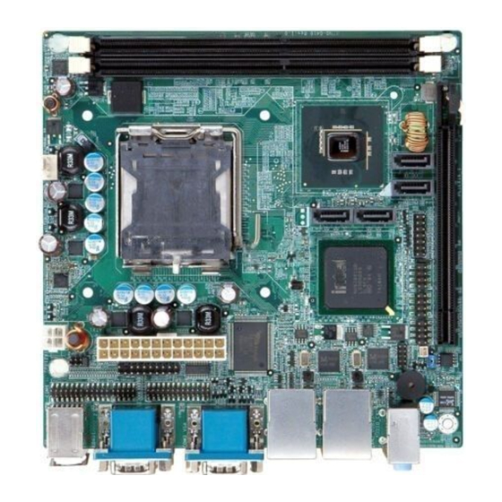
Mini-ITX SBC supports socket LGA775 Intel® Core™ 2 Quad CPU with
1333Mhz FSB, DDR3, VGA, Dual PCIe GbE, six COM, four SATAII and
Audio, ROHS
KINO-G410-R10
Quick Installation Guide
Version 1.0
Nov. 17th, 2010
Package Contents
KINO-G410-R10 package includes the following items:
1 x KINO-G410-R10 Single Board Computer
2 x SATA cable
1 x I/O shielding
1 x Mini Jumper Pack
1 x Utility CD
1 x One key Recovery Utility CD
1 x QIG (Quick Installation Guide)
©2006 Copyright by IEI Technology corp.
All rights reserved.
1
Advertisement

Related Manuals for IEI Technology KINO-G410-R10


Summary of Contents for IEI Technology KINO-G410-R10
- Page 1 KINO-G410-R10 Quick Installation Guide Version 1.0 Nov. 17th, 2010 Package Contents KINO-G410-R10 package includes the following items: 1 x KINO-G410-R10 Single Board Computer 2 x SATA cable 1 x I/O shielding 1 x Mini Jumper Pack 1 x Utility CD...
- Page 2 Specifications LGA775 45nm Intel® Core™2 Quad, Core™2 Duo, Pentium® D, Celeron® at FSB 800/1066/1333MHz processors System Chipset Intel® G41 + ICH7 Graphic Engine Intel® GMA X4500 BIOS UEFI BIOS System memory Two 240-pin 800/1066MHz Dual-Channel DDR3 SDRAM DIMM supported (system max. 8GB) Ethernet Dual Realtek RTL8111E PCIe GbE Controllers with ASF2.0 support I/O Interface...
-
Page 3: Ordering Information
Temperature: -10°C ~ 60°C Dimension: 170 mm x 170 mm Weight: GW: 1100g; NW: 700g Ordering Information KINO-G410-R10: Mini-ITX SBC supports socket LGA775 Intel® Core™ 2 Quad CPU with 1333MHz FSB, DDR3, VGA, Dual PCIe GbE, 6 COM, 4 SATAII and Audio, ROHS KINO-G410T-R10: Mini-ITX SBC supports socket LGA775 Intel®... - Page 4 JP2: COM6 Mode Selection DESCRIPTION Short 1-2(default) RS – 232(default) Short 3-4 RS - 422 Short 5-6 RS – 485 short 5-6 and7-8 RS485 with RTS control Table of Connectors LABEL FUNCTION KB_MS1 PS/2 MOUSE & KEYBOARD Connectors VGA1 VGA 15-pin Connector LAN1 RJ45 LAN Connectors LAN2...
- Page 5 VGA1: External 15-pin Connector PIN NO. DESCRIPTION PIN NO. DESCRIPTION GREEN BLUE CRT_PLUG# DDC_DATA HSYNC VSYNC DDC_CLK KBMS1: PS/2 KB/MS Connector PIN NO. DESCRIPTION PIN NO. DESCRIPTION KB_DATA KBPWR KB_CLK MS_DATA KBPWR MS_CLK KB_GND KB_GND COM1,2,3 : Serial port connector.( D-SUB) PIN NO.
- Page 6 COM6: Serial port connector,RS-232/422/485 DESCRIPTION DESCRIPTION RS422 TX2+/RS485+ RS422 TX2-/RS485- RS422 RX2- RS422 RX2- AUDIO_1: AUDIO Connector PIN NO. DESCRIPTION PIN NO. DESCRIPTION Line out_R Line in_R Line out_L Line in_L MIC_R MIC_L LAN1, LAN2: RJ45 LAN Connector PIN NO. DESCRIPTION PIN NO.
- Page 7 USB4_5,USB6-7: USB Connector PIN NO. DESCRIPTION PIN NO. DESCRIPTION USB- USB+ USB+ USB- CPU12V1: Power input connector PIN NO. DESCRIPTION PIN NO. DESCRIPTION +12V +12V ATX1: ATX POWER Input Connector PIN NO. DESCRIPTION PIN NO. DESCRIPTION 3.3V 3.3V 3.3V -12V PS_ON- 5VSB 3.3V...
- Page 8 LPT1: LPT Connector PIN NO. DESCRIPTION PIN NO. DESCRIPTION PTD0 PTD1 INITR PTD2 SLIN PTD3 PTD4 PTD5 PTD6 PTD7 -ACK BUSY SLCT JP4: VGA-LVDS Connector DESCRIPTION DESCRIPTION H-SYN Unpugged V-SYN +3.3V GREEN +3.3V BULE +3.3V 5VDDC_DATA +12V 5VDDC_CLK +12V SYS_FAN1: System Fan Connector PIN NO.
- Page 9 CPU_FAN1:CPU Fan Connector PIN NO. DESCRIPTION PIN NO. DESCRIPTION FAN_IN FANCTL JSPI1:Flash Bios Pin Header PIN NO. DESCRIPTION PIN NO. DESCRIPTION HOLD 3.3V DIO1:Digital Input and Output Pin Header PIN NO DESCRIPTION PIN NO. DESCRIPTION VCC5S GPO3 GPO2 GPO1 GPO0 GPI3 GPI2 GPI1...
- Page 10 Board Layout: Dimensions...
- Page 11 Board Layout: Jumper and Connector Locations...
Need help?
Do you have a question about the KINO-G410-R10 and is the answer not in the manual?
Questions and answers