Sign In
Upload
Manuals
Brands
IEI Technology Manuals
Motherboard
Kino-g410
IEI Technology Kino-g410 Manuals
Manuals and User Guides for IEI Technology Kino-g410. We have
2
IEI Technology Kino-g410 manuals available for free PDF download: User Manual, Quick Installation Manual
IEI Technology Kino-g410 User Manual (152 pages)
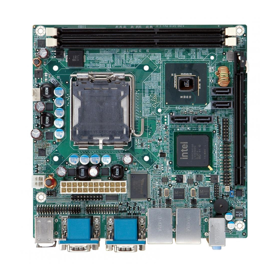
Mini-ITX Motherboard for Intel Core 2 Duo/Quad/Extreme CPU, 800/1066/1333 MHz FSB, DDR3, VGA, LAN, SATA 3Gb/s, PCIe x16, USB, HD Audio, RoHS Compliant
Brand:
IEI Technology
| Category:
Motherboard
| Size: 4.75 MB
Table of Contents
Table of Contents
5
Introduction
14
Benefits
15
Features
15
Introduction
15
Connectors
16
Figure 1-2: Connectors
16
Dimensions
17
Figure 1-3: Dimensions (MM)
17
Data Flow
18
Figure 1-4: Data Flow Diagram
18
Technical Specifications
19
Table 1-1: Technical Specifications
20
2 Packing List
21
Anti - Static Precautions
22
Unpacking Precautions
22
Packing List
23
Table 2-1: Packing List
23
Optional Items
24
Table 2-2: Optional Items
25
Connectors
26
Figure 3-1: Connectors and Jumpers
27
Layout
27
Peripheral Interface Connectors
27
External Interface Panel Connectors
28
Figure 1-1: KINO-G410
28
Peripheral Interface Connectors
28
Table 3-1: Internal Peripheral Connectors
28
Battery Connector
29
Figure 3-2: Battery Connector Location
29
Internal Peripheral Connectors
29
Table 3-2: External Peripheral Connectors
29
CPU Fan Connector
30
Figure 3-3: CPU Fan Connector Location
30
Table 3-3: Battery Connector Pinouts
30
Table 3-4: CPU Fan Connector Pinouts
30
CPU Power Input Connector
31
Figure 3-4: CPU Fan Connector Location
31
System Fan Connector
31
Table 3-5: CPU Fan Connector Pinouts
31
Digital I/O Connector
32
Figure 3-5: CPU Power Input Connector Location
32
Figure 3-6: Digital I/O Connector Locations
32
Table 3-6: CPU Power Input Connector Pinouts
32
Figure 3-7: Front Panel Connector Location
33
Front Panel Connector
33
Table 3-7: Digital I/O Connector Pinouts
33
Figure 3-8: Memory Card Slot Location
34
Memory Slot
34
Parallel Port Connector
34
Table 3-8: Front Panel Connector Pinouts
34
Figure 3-9: Parallel Port Connector Location
35
Table 3-9: Parallel Port Connector Pinouts
35
Figure 3-10: Power Connector Location
36
Power Connector
36
Table 3-10: Power Connector Pinouts
36
Figure 3-11: Serial Port Connector Location
37
Serial Port Connector
37
Table 3-11: Serial Port Connector Pinouts
37
Figure 3-12: RS-232/422/485 Serial Port Connector Location
38
RS-232/422/485 Serial Port Connector
38
Table 3-12: RS-232/422/485 Serial Port Connector Pinouts
38
Figure 3-13: SATA Drive Connector Location
39
SATA Drive Connectors
39
Smbus Connector
39
Figure 3-14: Smbus Connector Location
40
Figure 3-15: SPI Flash Connector
40
SPI Flash Connector
40
Table 3-13: Smbus Connector Pinouts
40
Figure 3-16: USB Connector Pinout Locations
41
Table 3-14: SPI Flash Connector
41
Table 3-15: USB Port Connector Pinouts
41
USB Connectors
41
Figure 3-17: VGA to LVDS Connector Location
42
Table 3-16: VGA to LVDS Connector Pinouts
42
VGA to LVDS Connector
42
Audio Connector
43
External Peripheral Interface Connector Panel
43
Figure 3-18: External Peripheral Interface Connector
43
Figure 3-19: Audio Connector
43
Figure 3-20: PS/2 Pinout and Configuration
44
Keyboard/Mouse Connector
44
LAN Connector
44
Table 3-17: Keyboard Connector Pinouts
44
Figure 3-21: Serial Port Pinouts
45
Serial Port Connectors (COM1, COM2 and COM3)
45
Table 3-18: LAN Pinouts
45
Table 3-19: Serial Port Pinouts
45
Figure 3-22: VGA Connector
46
Table 3-20: USB Port Pinouts
46
USB Connector
46
VGA Connector
46
Table 3-21: VGA Connector Pinouts
47
4 Installation
48
Anti Static Precautions
49
Installation Considerations
49
Basic Installation
51
CPU Installation
51
Figure 4-1: Intel LGA775 Socket
51
Figure 4-2: Remove Protective Cover
52
Figure 4-3: CPU Socket Load Plate
52
Figure 4-4: Insert the Socket LGA775 CPU
53
Cooling Kit Installation
54
Figure 4-5: Cooling Kits
54
Figure 4-6: Securing the Heat Sink to the KINO-G410
55
DIMM Installation
56
Figure 4-7: DIMM Installation
56
Motherboard Installation
56
Clear CMOS Jumper
57
Jumper Settings
57
Table 4-1: Jumpers
57
COM 6 Function Select Jumper
58
Figure 4-8: Clear BIOS Jumper Location
58
Table 4-2: Clear BIOS Jumper Settings
58
Table 4-3: COM 6 Function Select Jumper Settings
58
Figure 4-9: COM 6 Function Select Jumper Location
59
Internal Peripheral Device Connections
59
SATA Drive Connection
59
Figure 4-10: SATA Drive Cable Connection
60
Figure 4-11: SATA Power Drive Connection
61
USB Cable (Dual Port) with Slot Bracket
61
Audio Connector
62
External Peripheral Interface Connection
62
Figure 4-12: Dual USB Cable Connection
62
Figure 4-13: Audio Connector
63
PS/2 Keyboard and Mouse Connection
63
Figure 4-14: PS/2 Keyboard/Mouse Connector
64
LAN Connection
64
Figure 4-15: LAN Connection
65
Serial Device Connection
65
Figure 4-16: Serial Device Connector
66
USB Device Connection
66
Figure 4-17: USB Connector
67
VGA Monitor Connection
67
Figure 4-18: VGA Connector
68
Software Installation
68
Bios
69
Introduction
70
Starting Setup
70
Using Setup
70
Getting Help
71
Unable to Reboot after Configuration Changes
71
BIOS Menu Bar
71
Table 5-1: BIOS Navigation Keys
71
Main
72
System Date [XX/XX/XX]
72
System Overview
72
System Time [XX:XX:XX]
72
Advanced
73
CPU Configuration
74
IDE Configuration
74
BIOS Menu 3: CPU Configuration
74
BIOS Menu 4: IDE Configuration
75
ATA/IDE Configuration [Enhanced]
75
Configure SATA as [IDE]
75
IDE Master and IDE Slave
75
IDE Master, IDE Slave
76
BIOS Menu 5: IDE Master and IDE Slave Configuration
76
32Bit Data Transfer [Enabled]
76
Auto-Detected Drive Parameters
76
Auto]
76
Block (Multi Sector Transfer) [Auto]
76
DMA Mode [Auto]
76
Lba/Large Mode [Auto]
76
PIO Mode [Auto]
76
Type [Auto]
76
Super IO Configuration
81
BIOS Menu 6: Super IO Configuration
81
Serial Port1 Address [3F8]
81
Serial Port1 IRQ [IRQ4]
81
Serial Port2 Address [2F8]
81
Serial Port2 IRQ [IRQ3]
81
Serial Port3 IRQ [IRQ11]
81
Serial Port4 Address [2E8]
81
Serial Port4 IRQ [IRQ10]
81
Serial Port5 Address [338]
81
IR Function [COM6]
84
Parallel Port Address [378]
84
Parallel Port Mode [Normal]
84
Parallel Port IRQ [IRQ7]
85
Hardware Health Configuration
86
BIOS Menu 7: Hardware Health Configuration
86
CPU Fan1 Highest Setting [100]
86
CPU FAN1 Mode Setting [Auto Fan by RPM]
86
CPU Temp. Limit of Highest / Second / Third / Lowest [N]
86
SYS Fan1 Highest Setting [100]
86
SYS FAN1 Mode Setting [Auto Fan by RPM]
86
Monitored Values
88
SYS Fan1 Second / Third / Fourth / Lowest Setting [N]
88
Power Configuration
89
BIOS Menu 8: Power Configuration
89
ACPI Configuration
90
APM Configuration
90
BIOS Menu 9: ACPI Configuration
90
Suspend Mode [S1 (POS)]
90
BIOS Menu 10: Advanced Power Management Configuration
91
Restore on AC Power Loss [Last State]
91
Resume on RTC Alarm [Disabled]
91
Remote Access Configuration
92
BIOS Menu 11: Remote Access Configuration
92
Base Address, IRQ [3F8H,4]
92
Redirection after BIOS POST [Always]
92
Remote Access [Disabled]
92
Serial Port Mode [115200 8,N,1]
92
Serial Port Number [COM1]
92
Terminal Type [ANSI]
92
USB Configuration
95
BIOS Menu 12: USB Configuration
95
USB 2.0 Controller [Enabled]
95
USB Functions [Enabled]
95
Legacy USB Support Enabled
96
Pci/P N P
96
USB 2.0 Controller Mode [Hispeed]
96
BIOS Menu 13: Pci/Pnp Configuration
97
Reserved Memory Size [Disabled]
97
Boot
99
Boot Settings Configuration
99
BIOS Menu 15: Boot Settings Configuration
99
Addon ROM Display Mode [Force BIOS]
99
Quick Boot [Enabled]
99
Quiet Boot [Enabled]
99
Bootup Num-Lock [On]
100
Security
101
BIOS Menu 16: Security
101
Boot from LAN Support [Disabled]
101
Change Supervisor Password
101
Change User Password
101
Chipset
103
North Bridge Chipset Configuration
103
BIOS Menu 17: Chipset
103
BIOS Menu 18: North Bridge Chipset Configuration
104
Boot Display Device [Auto]
104
Initate Graphic Adapter [PEG/IGD]
104
Internal Graphics Mode Select [Enabled, 32MB]
104
Memory Hole [Disabled]
104
South Bridge Chipset Configuration
105
BIOS Menu 19: South Bridge Chipset Configuration
105
Exit
106
BIOS Menu 20: Exit
106
A Bios Options
108
A BIOS Op Tio N S
109
B Terminology
112
C One Key Recovery
116
One Key Recovery Introduction
117
Figure C-1: IEI One Key Recovery Tool Menu
117
System Requirement
118
Supported Operating System
119
Setup Procedure for Windows
120
Hardware and BIOS Setup
120
C.2.2 Create Partitions
121
Create Partitions
121
Figure C-2: Launching the Recovery Tool
121
Figure C-3: Recovery Tool Setup Menu
122
Figure C-4: Command Mode
122
Figure C-5: Partition Creation Commands
123
Install Operating System, Drivers and Applications
124
Build-Up Recovery Partition
125
Figure C-6: Launching the Recovery Tool
125
Figure C-7: System Configuration for Windows
125
C.2.4 Build-Up Recovery Partition
125
Figure C-8: Build-Up Recovery Partition
126
Figure C-9: Press any Key to Continue
126
Create Factory Default Image
127
Figure C-10: Press F3 to Boot into Recovery Mode
127
Figure C-11: Recovery Tool Menu
127
C.2.5 Create Factory Default Image
127
Figure C-12: about Symantec Ghost Window
128
Figure C-13: Symantec Ghost Path
128
Figure C-14: Select a Local Source Drive
129
Figure C-15: Select a Source Partition from Basic Drive
129
Figure C-16: File Name to Copy Image to
130
Figure C-17: Compress Image
130
Figure C-18: Image Creation Confirmation
131
Figure C-19: Image Creation Process
131
Figure C-20: Image Creation Complete
131
Setup Procedure for Linux
132
Figure C-21: Press any Key to Continue
132
C.3 S Etup P Rocedure for L Inux
132
Figure C-22: Partitions for Linux
133
Figure C-23: System Configuration for Linux
134
Figure C-24: Access Menu.lst in Linux (Text Mode)
134
Recovery Tool Functions
135
Figure C-25: Recovery Tool Menu
135
C.4 R Ecovery T Ool F Unctions
135
Figure C-26: Recovery Tool Main Menu
136
Factory Restore
137
Figure C-27: Restore Factory Default
137
Figure C-28: Recovery Complete Window
137
Backup System
138
Figure C-29: Backup System
138
Figure C-30: System Backup Complete Window
138
Restore Your Last Backup
139
Figure C-31: Restore Backup
139
Figure C-32: Restore System Backup Complete Window
139
Manual
140
Figure C-33: Symantec Ghost Window
140
C.4.4 Manual
140
Other Information
141
C.5 O Ther I Nformation
141
Using AHCI Mode or Ali M5283 / VIA VT6421A Controller
141
System Memory Requirement
143
D Watchdog Timer
144
E Digital I/O Interface
147
Introduction
148
Dio Connector Pinouts
148
Assembly Language Example
148
E.1 I Ntroduction
148
F Hazardous Materials Disclosure
149
Hazardous Materials Disclosure Table for Ipb Products Certified as R Ohs Compliant under 2002/95/Ec Without Mercury
150
Advertisement
IEI Technology Kino-g410 Quick Installation Manual (11 pages)
Mini-ITX SBC supports socket LGA775 Intel Core 2 Quad CPU with 1333Mhz FSB, DDR3, VGA, Dual PCIe GbE, six COM, four SATAII and Audio, ROHS
Brand:
IEI Technology
| Category:
Motherboard
| Size: 0.14 MB
Advertisement
Related Products
IEI Technology KINO-G45A
IEI Technology KINO-G410-R10
IEI Technology KINO-G410T-R10
IEI Technology KINO-GM45A
IEI Technology KINO-9653
IEI Technology KINO-9454
IEI Technology KINO-6614
IEI Technology KINO-AH611
IEI Technology KINO-AA750-i2
IEI Technology KINO-QM57A
IEI Technology Categories
Motherboard
Touch Panel
Computer Hardware
Single board computers
Desktop
More IEI Technology Manuals
Login
Sign In
OR
Sign in with Facebook
Sign in with Google
Upload manual
Upload from disk
Upload from URL