
Subscribe to Our Youtube Channel
Related Manuals for AEC ACM Series

Summary of Contents for AEC ACM Series
- Page 1 Operation and Installation Manual ACM Series Dehumidifying Dryers Important! Read Carefully Before Attempting to Install or Operate Equipment Part No. A0570044 Revision NEW Bulletin No. WH1-620...
- Page 2 Performance figures stated in this manual are based on a standard atmosphere of 59°F (15°C) at 29.92” Hg (1,014 millibars) at sea level, using 60 hz power. Altitude is an important consideration when specifying dehumidifying dryers. AEC can advise you on proper selection and sizing of systems for your operating environment.
-
Page 3: Table Of Contents
Restoring the E5CK Dew Point Meter to Factory Setup..........39 5-10 Redundant Safety Controller Display ................ 40 5-11 Setting the Redundant Safety Controller ..............40 5-12 Restoring the WATLOW Redundant Safety Controller to Factory Setup ....40 ACM Series Dehumidifying Dryers Page 3... - Page 4 12-1 Contact Information for Technical Assistance ............... 61 12-2 Returned Material Policy ....................62 12-3 Warranty ........................63 Safety Tag Information ............. 65 13-1 ACM Dryer Safety Tags ....................65 13-2 Dryer Identification (Serial Number) Tag..............66 Page 4 ACM Series Dehumidifying Dryers...
- Page 5 Safety Considerations AEC ACM Series membrane dryers are designed to provide safe and reliable operation when installed and operated within design specifications, following national and local safety codes. To avoid possible personnel injury or equipment damage when installing, operating, or maintaining this equipment, use good judgment and follow these safe practices: Follow all SAFETY CODES.
- Page 6 Wood Dale, IL 60191 Phone: 630.595.1060 Fax: 630.595.6641 The equipment is distributed in Europe by our European facility: ACS-EUROPE Daniels Industrial Estate BATH ROAD Stroud, Gloucestershire, England GL5 3TJ Phone: (44) 1453 768980 Fax: (44) 1453 768990 Page 6 ACM Series Dehumidifying Dryers...
-
Page 7: Annex B Information
An inspection report detailing the functional test is included with the dryer. The machine is not equipped with cableless controls. Color-coded (harmonized) power cord is sufficient for proper installation. ACM Series Dehumidifying Dryers Page 7... - Page 8 Charts and Figures Typical ACM Dryer Components Typical Dryer Air Flow Schematic ACM Series Machine-Mount Dimensions ACM Series Floor-Mount Dimensions Suggested Lift Rigging for ACM Dryers (Cart Mount) Suggested Lift Rigging for ACM Dryers (Floor Mount) Suggested Lift Rigging for ACM Dryers (Machine Mount)
-
Page 9: General Information
Moisture removal from hygroscopic (moisture attracting) plastic pellets is an essential step in the manufacture of high-quality plastic products. AEC dehumidifying dryers are used to generate very low dew point air heated to a controlled temperature for drying plastic pellets and regrind. -
Page 10: Standard Features
• Process/regeneration heater box • High temperature safety system (Process/Regeneration) Options Options can tailor your AEC dehumidifying dryer to meet the exact requirements of the drying task being performed. Process temperature up to 400ºF (or below 160ºF), including pyrex sight glass and silicone insulated delivery hose. -
Page 11: Typical Acm Dryer Components
Figure 1 Typical ACM Dryer Components Standard Air Filter Heater Box Pressure Pressure High Switch Gage Membrane Temperature Solenoid Dryer Switch Valve Compressed Air Inlet Coalescing Oil Filter Air Filter 0.01 Micron Optional Dust Collector ACM Series Dehumidifying Dryers Page 11... -
Page 12: The Drying System
The Drying System AEC Membrane Compressed air dryers, take a small percentage of the dried gas and direct it back in a sweeping pattern through the module shell. This provides a driving force to remove the moisture with the minimum purge required. -
Page 13: Acm Series Machine-Mount Dimensions
Figure 3 ACM Series Machine-Mount Dimensions Mounting flange Diameter hole: Notes: Hopper mounting flanges on 0.75 and and 1.5 cu. ft. (20 & 40 liter) hoppers are supplied blank so the customer can drill to match existing machine throat. 3.0 cu. ft. (80 liter) hoppers and larger are not supplied with a cast flange (as shown). -
Page 14: Specifying A Drying System
Many variables were considered in the selection of your drying system, including type of materials, residence time, throughput of the extruder or injection molding machine. Should your operating environment change, AEC can advise you on necessary equipment and process time and temperature modifications required for your system. -
Page 15: Safety
Obey these specific work rules: Read and follow the instructions in this manual before installing, operating, or maintaining any equipment. Additional copies are available from AEC, Inc. Only qualified persons should work on, or with, this equipment. Work only with approved tools and devices. -
Page 16: Safety Considerations
NOTE: If you believe that your equipment has a defect which could cause injury, you should immediately discontinue its use and inform AEC, Inc., at our address listed in this manual. The principle factors which can result in injury are: Failure to follow proper operating and clean-out procedures, i.e. -
Page 17: General Responsibility
Your employer probably has established a set of safety rules in your workplace. Those rules, this manual, or any other safety information will not keep you from being injured while operating your equipment. ACM Series Dehumidifying Dryers Page 17... - Page 18 • NEVER stand or sit where you could slip or stumble into the dryer while working on it. • DO NOT wear loose clothing or jewelry, which can be caught while working on a dryer. In addition, cover or tie back long hair. Page 18 ACM Series Dehumidifying Dryers...
-
Page 19: Maintenance Responsibility
Install in accordance with national and local codes, which apply. When you have completed the repair or maintenance procedure, check your work, remove your tools, rigging, and handling equipment. ACM Series Dehumidifying Dryers Page 19... -
Page 20: Safety
Every effort has been made to incorporate these standards into the design of the ACM Dryer; however, it is the responsibility of the personnel operating and maintaining the equipment to familiarize themselves with the safety procedures and the proper use of any safety devices. Page 20 ACM Series Dehumidifying Dryers... -
Page 21: Fail Safe Operation
These tags are available at most electrical supply stores. WARNING! Disconnect both of these items to ensure optimum maintenance personnel safety when cleaning or servicing this equipment. ACM Series Dehumidifying Dryers Page 21... - Page 22 -Notes- Page 22 ACM Series Dehumidifying Dryers...
-
Page 23: Shipping Information
Lading is attached to our original invoice. If the shipment was prepaid, write us for a receipted transportation bill. Advise AEC, Inc. regarding your wish for assistance and to obtain an RMA (return material authorization) number. ACM Series Dehumidifying Dryers... -
Page 24: If The Shipment Is Not Complete
Notify AEC, Inc. immediately of the shortage. If the Shipment is Not Correct If the shipment is not what you ordered, contact AEC, Inc. immediately. For shipments in the United States and Canada, call 1 (630) 475-7143; for all other countries, call 001 (630) 475-7143. -
Page 25: Installation
4C on the following pages show a suggested safe rigging diagram. It lets you lift the dryer/hopper unit vertically for installation on the machine throat. Adjust chain lengths at the center sling bracket before you lift the unit. Your dryer has built-in lifting lugs. ACM Series Dehumidifying Dryers Page 25... -
Page 26: Suggested Lift Rigging For Acm Dryers (Cart Mount)
Dryer and/or injury to personnel! Item Quantity Description Vendor Vendor part no. Adjustable alloy chain sling McMaster-Carr 33665T32 Existing hopper lifting bracket — — Drop forged steel eye nut McMaster-Carr 3019T15 Chain connector McMaster-Carr 3712T23 Page 26 ACM Series Dehumidifying Dryers... -
Page 27: Suggested Lift Rigging For Acm Dryers (Floor Mount)
(3) locations/lifting points on the unit! Moving the Dryer without the chains attached to all of the lifting points will cause the unit to become unstable and may cause damage to the Dryer and/or injury to personnel! ACM Series Dehumidifying Dryers Page 27... -
Page 28: Making Electrical Connections
Drying hopper air inlet and outlet locations vary, but always connect hoses so the dry process air from the dryer enters the bottom of the drying hopper and flows out the top to return to the dryer inlet. Page 28 ACM Series Dehumidifying Dryers... -
Page 29: Drying Hopper Air Trap Considerations
Drying Hopper Air Trap Considerations AEC’s exclusive air trap assembly on the top of the drying hopper prevents ambient air from contaminating the material being dried. Keep the material level at the mid point of the air trap for the dryer to operate efficiency. - Page 30 - Notes - Page 30 ACM Series Dehumidifying Dryers...
-
Page 31: Controls
This feature works in conjunction with the alarm horn to warn the operator of a high bed safety temperature, a regeneration heater fault, or a blower failure. This warning is reset by pressing the alarm silence button. ACM Series Dehumidifying Dryers Page 31... -
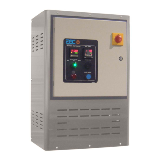
Page 32: Typical Control Panel
Figure 6 Typical Control Panel Page 32 ACM Series Dehumidifying Dryers... -
Page 33: Process Air Temperature Controller
Process Air Temperature Controller AEC dryers use a microprocessor-based PID temperature controller for maintaining process air temperature. The controller is a modular, self-contained unit you can remove from the mounting housing. All parameters except for the process air set point are factory set and adjusted; normally, no field adjustment to the internal controls is necessary. -
Page 34: Identifying Process Air Temperature Controller Led Indicators
ALARM1 exceeds the set point temperature by more than the alarm deviation value. Alarm output de-energizes the heaters. Heaters re-energize when the temperature falls within the acceptable range. Page 34 ACM Series Dehumidifying Dryers... -
Page 35: Identifying Temperature Controller Keys
To change the process air temperature set point with the dryer running: Press to raise the set point to the temperature you want. Press to lower the set point to the temperature you want. ACM Series Dehumidifying Dryers Page 35... -
Page 36: Restoring The E5Cn Temperature Controller To Factory Setup
The E5CN controller has several mode selections. Within each mode are numerous parameters that can be set. The factory at AEC sets the security level to protect the critical parameters from being accidentally changed. Below is an explanation of the operating modes you will have access to and the AEC default settings. - Page 37 Use short presses on the Mode Display key to display each parameter within a mode. readout displays the different values for the parameter within a mode. ACM Series Dehumidifying Dryers Page 37...
-
Page 38: Process Air Dew Point Display
Process Air Dew Point Display Optional The Process Air Dew Point meter indicates the current process air delivery moisture content. Standard AEC dryers use a microprocessor-based controller for displaying dew point air temperature. The controller is a modular, self-contained unit removable from the mounting housing. -
Page 39: Setting The High Dew Point Alarm
If the preset parameters on the controller have been tampered with and it no longer functions properly, call the Service Department at AEC. This controller is not meant to be modified. Note: The dew point alarm monitors and indicates a deviation from the set point. -
Page 40: Redundant Safety Controller Display
Controller to Factory Setup If the preset parameters on the controller have been tampered with and it no longer functions properly, call the Service Department at AEC. This controller is not meant to be modified. Page 40 ACM Series Dehumidifying Dryers... - Page 41 WATLOW Operating Parameters The WATLOW controller has only one mode selection; ALARM. The factory at AEC sets the security level to protect the critical parameters from being accidentally changed. Below is an explanation of the modes you will have access to and the AEC default settings.
-
Page 42: Setting List For Redundant Safety Controller (Watlow)
Set, Limit 3 High Set, Alarm 3 Low Set, Alarm 3 High Set (0) no lockout, (1) Programming and Setup Page Locked, (2) Limit Lockout Set Points are the only Operation Page parameters accesible, (3) Full Lockout. Page 42 ACM Series Dehumidifying Dryers... -
Page 43: Control Operation
5.) If the pressure in the system drops below 15 PSI for 10 seconds or more, the alarm will sound. The process heater and solenoid valve will shut off. ACM Series Dehumidifying Dryers Page 43... -
Page 44: Controller Operation
3.) Once the control power is on and no fault conditions exist, turning the Off-On-Start switch to the START position will start the dryer as follows: 3-1. The process heater is turned on and controlled by the E5CN controller. Page 44 ACM Series Dehumidifying Dryers... - Page 45 7.) The dryer is shut off by turning the control power switch to the OFF position. 8.) Refer to Schematic drawing A0566087 enclosed in the control enclosure. ACM Series Dehumidifying Dryers Page 45...
-
Page 46: Alarm Display Messages
Regen Heater Temp Switch and/or HIGH TEMP Process Heater Temp Switch and/or FAULT Redundant Temp Safety Insufficient Air Pressure to Run Unit Alarm AIR PRES SW Multiple Alarms HIGH TEMP FAULT No Alarms SYSTEM NORMAL Page 46 ACM Series Dehumidifying Dryers... -
Page 47: Startup, Shutdown, And Operation
After the proper pre-drying time for the initial hopper fill has elapsed, fully open the drying hopper slide gate. Note: To allow proper residence time during continuous processing, maintain the material level in the hopper at the midpoint of the air trap assembly. ACM Series Dehumidifying Dryers Page 47... -
Page 48: Shutting Down The Dryer
ON/OFF Turn the system switch to ON/OFF If needed, empty the drying hopper. For maintenance or a long term shutdown, open (de- energize) the electrical disconnects at the dryer and at the power drop. Page 48 ACM Series Dehumidifying Dryers... -
Page 49: Maintenance
Keep these operating instructions on hand and follow them when installing, operating, or maintaining your dryer. If the instructions become damaged or unreadable, you can obtain additional copies from AEC. Only qualified personnel familiar with this equipment should work on or with this unit. - Page 50 Recommendations for Cleaning and Replacing Filters Turn off and/or lock out electrical power to the dryer. Remove the back access cover. Locate the 2 compressed air hoses and filter bowls connected to the filters. Remove the filter bowls Page 50 ACM Series Dehumidifying Dryers...
- Page 51 Important! DO NOT clean/wash filter with water! After each cleaning: • Inspect the filter element. Briefly hold a light bulb behind the element and look for any fatigued paper or residual dirt. ACM Series Dehumidifying Dryers Page 51...
-
Page 52: Servicing The Dew Point Monitor
The sensor will be destroyed! Replacing the Process Heater The ACM Series dehumidifying dryers utilize a single-phase Calrod-type heater element. This heater element is mounted in the center compartment below the desiccant beds. Although the replacement procedure is the same for each heater, the wattage varies by model, voltage, temperature range, etc. -
Page 53: Process Heater Location & Disassembly
Install new heater gaskets and securely tighten all fasteners. CAUTION! Heater loops should not touch each other. “Hot spots” lead to premature heater failure! Reinstall the wires based on the sketch you made earlier. ACM Series Dehumidifying Dryers Page 53... - Page 54 Lock out electrical power and check heater elements for continuity using an ohmmeter. Check dew point and temperature tracking with an external dew point monitor and pyrometer. - Photocopy this page for your maintenance records - Page 54 ACM Series Dehumidifying Dryers...
-
Page 55: Troubleshooting
Insufficient power to PLC Check power supply and power off. (Power light is off). wiring to PLC. Faulty PLC (PLC Power light is on, Run light is off, and/or Error Replace PLC. light is on). ACM Series Dehumidifying Dryers Page 55... - Page 56 Power switch not set to ON. switch and control power switch Control Power fuse blown. No setting change possible on The key protection switch is set Set the key protection switch to temperature controller. to ON. OFF. Page 56 ACM Series Dehumidifying Dryers...
-
Page 57: Determining Temperature Controller Errors Or Sensor Errors
, the controller is normal and the sensor is probably broken, –B short-circuited, or incorrectly wired. Other service problems or questions can be answered by contacting the AEC Service Department. ACM Series Dehumidifying Dryers Page 57... -
Page 58: Dryer Options
The following is a list of options, which your Dryer may have been equipped with: • Dew Point Monitor • Audible Alarm with Silence Button • High Temperature Option (with Aftercooler) • Casters • AP1 PLC Control System Page 58 ACM Series Dehumidifying Dryers... -
Page 59: Spare Parts
Spare Parts 11-1 Spare Parts List ACM Series Dehumidifying Dryers Figure 14 Level 1 Spare Parts List (Electrical & Mechanical) MINI DRYER SPARE PARTS LIST ACM30, ACM60 LEVEL 1 ( Electrical Components ) PART # SIZE Description A0568932 Fuse for the Heater Elements... -
Page 60: Level 2 & 3 Spare Parts List (Electrical & Mechanical)
Dew Point Sensor Manifold A0548558 Gasket for the Dew Point Sensor W00015436 Plastic Nut for the Dew Point Sensor A0568022 Rubber Bumper for the bottom of Dryer A0568023 Swivel Casters without Brakes A0568024 Swivel Casters with Brakes Page 60 ACM Series Dehumidifying Dryers... -
Page 61: Technical Assistance
Contract Department Call [ 630 ] 595-1060 Monday–Friday, 8am–5pm CST Let AEC install your system. The Contract Department offers any or all of these services: project planning; system packages including drawings; equipment, labor, and construction materials; and union or non-union installations. -
Page 62: Returned Material Policy
12-2 Returned Material Policy 12-2-1 Credit Returns Prior to the return of any material authorization must be given by AEC, INC. A RMA number will be assigned for the equipment to be returned. Reason for requesting the return must be given. -
Page 63: Warranty
12-3 Warranty AEC, Inc. warrants all equipment manufactured by it to be free from defects in workmanship and material when used under recommended conditions. The Company’s obligation is limited to repair or replace FOB the factory any parts that are returned prepaid within one year of equipment shipment to the original purchaser, and which, in the Company’s opinion, are defective. - Page 64 -Notes- Page 64 ACM Series Dehumidifying Dryers...
-
Page 65: Safety Tag Information
Safety Tag Information 13-1 ACM Dryer Safety Tags Hot! Read Operation and Installation Manual High Voltage Earth Ground Inside Enclosure Protected Earth Lifting Point Ground ACM Series Dehumidifying Dryers Page 65... -
Page 66: Dryer Identification (Serial Number) Tag
Date of Manufacture 06/2003 4.5A Over-current Protection Device (s) 4.5A Total Frequency 50/60Hz Compressed air supply None Dryer Mass 400 lbs/(180 KG) Electrical Diagrams & Pneumatic Diagram 801 AEC Drive Wood Dale, Illinois USA (630) 595-1060 Page 66 ACM Series Dehumidifying Dryers... -
Page 67: Service Notes
Service Notes ACM Series Dehumidifying Dryers Page 67... - Page 68 Service Notes Page 68 ACM Series Dehumidifying Dryers...
- Page 69 Service Notes ACM Series Dehumidifying Dryers Page 69...
- Page 70 Service Notes Page 70 ACM Series Dehumidifying Dryers...
- Page 71 Warranty AEC, Inc. warrants all equipment manufactured by it to be free from defects in workmanship and material when used under recommended conditions. The Company’s obligation is limited to repair or replace FOB the factory any parts that are returned prepaid within one year of equipment shipment to the original purchaser, and which, in the Company’s opinion, are defective.
- Page 72 801 AEC Drive • Wood Dale, IL 60191-1198 USA (630) 595-1060 • Fax (630) 595-6641 http://www.aecinternet.com...
Need help?
Do you have a question about the ACM Series and is the answer not in the manual?
Questions and answers