ELECRAFT KX3 Assembly Manual
Ultra-portable 160-6 meter, all-mode transceiver
Hide thumbs
Also See for KX3:
- Owner's manual (55 pages) ,
- Installation and operation manual (17 pages) ,
- Installation instructions manual (14 pages)

Subscribe to Our Youtube Channel
Related Manuals for ELECRAFT KX3


Summary of Contents for ELECRAFT KX3
- Page 1 LECRAFT LTRA PORTABLE 160-6 METER MODE RANSCEIVER SSEMBLY ANUAL Revision G6, February 19, 2015 Copyright © 2015, Elecraft, Inc. All Rights Reserved...
-
Page 2: Table Of Contents
Assembly Procedure ..........................7 Front Panel Assembly ............................8 Bottom Cover Assembly ........................... 20 Final Assembly ..............................37 Setup and Operation ..........................42 Appendix A Illustrated Parts List…...................... A1 Elecraft manuals with color images may be downloaded from www.elecraft.com. -
Page 3: Introduction
KX3 easy to build, even if you’ve had no prior kit-building experience. Every modern transceiver is complex, and the KX3 is no exception. But all of the circuits are contained on a few factory-assembled and tested circuit boards. Also, virtually all of the alignment of your KX3 is handled in firmware using the KX3’s built-in test capabilities. - Page 4 Who is covered: This warranty covers the original owner of the Elecraft product as disclosed to Elecraft at the time of order. Elecraft products transferred by the purchaser to a third party, either by sale, gift, or other method, who is not disclosed to Elecraft at the time of original order, are not covered by this warranty.
-
Page 5: Preventing Electrostatic Discharge Damage
Preventing Electrostatic Discharge Damage Sensitive components may be damaged by Electrostatic Discharge (ESD) simply by touching them or a circuit board containing them unless you take specific steps to prevent such damage. Damage may occur with static discharges far too little for you to notice. A damaged component may not fail completely at first. -
Page 6: Overview Of The Kit
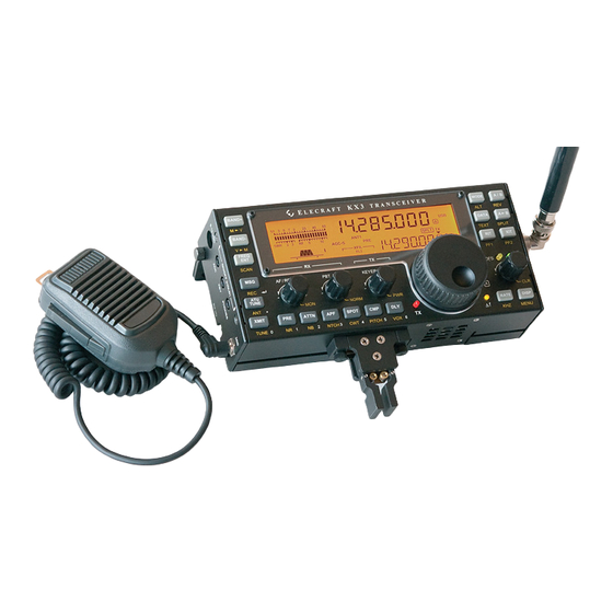
Figure 1. Complete KX3. All of the basic KX3 circuits are contained on the two larger pc boards: the Control Panel (CP) board in the top cover and the Radio Frequency (RF) circuit board in the bottom cover. Options plug into these boards, such as... -
Page 7: Tools Required For Assembly
Tools Required for Assembly 1. ESD Protection (see Preventing Electrostatic Discharge Damage, pg 3) 2. #0 and #1 size Phillips screwdrivers. To avoid damaging screws and nuts, a power screwdriver is not recommended. Always use the screwdriver that best fits the screw in each step. You may need a second screwdriver for tightening certain screws (see page 36) 3. - Page 8 A number of different types and sizes of screws and washers are used in the assembly. It is very important that you use the screw specified in each location or your finished KX3 may not fit together properly. In some places, using the wrong size screw may damage components.
-
Page 9: Assembly Procedure
Check off the steps as you finish each one. Skipping a step is easy to do without taking a moment to be certain that you completed the previous step. This can result in serious damage to your KX3 or, as a minimum, having to disassemble it to correct the mistake. -
Page 10: Front Panel Assembly
Front Panel Assembly Inspect the inside surface and tabs at the ends of the KX3 front panel sheet metal and remove the masking tape from the areas shown in Figure 4. Failure to provide good electrical contact at all the points shown may seriously degrade the performance of your KX3. - Page 11 Inspect the inside surface of the side panels. Remove any masking tape and ensure the metal is clean in the areas shown in Figure 6. Figure 6. Side Panels Clean Contact Areas. NOTE: Areas of the bottom cover also need to be clean. If you wish to do all the metal cleaning at once, turn to pg 20 before returning here to continue the assembly.
- Page 12 The speaker contains a very strong magnet that easily picks up hardware, bits of wire, etc. Be sure nothing is picked up by the speaker. Check both the cone in the front and the magnet at the back. Place the speaker with the cone upwards and place the gasket on the frame as shown in Figure 8. Figure 8.
- Page 13 Taking ESD precautions, remove the control panel (CP) board assembly from its protective envelope. Handle the assembly carefully to avoid damaging it or smudging the face of the LCD. Install the three standoffs as shown in Figure 9. Be sure you put the correct size hardware in each location and that you include all of the lock washers shown.
- Page 14 Install the standoff on the CP board as shown in Figure 10. Note that a M-F standoff is used instead of a screw on the back of the board. Figure 10. Installing CP Board Standoff Hardware - Part 2. Install the remaining standoff on the CP board as shown in Figure 11. Note that this standoff uses larger 4- 40 hardware and a M-F standoff on the back side of the board.
- Page 15 Turn the control panel board assembly over and inspect it to be sure that the standoffs are in the correct locations as shown in Figure 12. Also, confirm that you a placed a lock washer between each standoff and screw and the pc board.
- Page 16 Verify that you placed a lock washer between the 4-40 standoff and the pc board as shown in Figure 13. Inspect the front of the display for smudges or dust. Remove smudges by wiping it gently with a soft cloth. Blow off any dust.
- Page 17 Locate the VFO encoder, lock washer and two hex nuts. Thread one nut onto the shaft until it reaches the end of the threads as shown in Figure 15. Note that a small gap between the nut and the encoder body is normal. Figure 15.
- Page 18 Plug the speaker connector into J7 next to the VFO encoder board (see Figure 17). Figure 17. Connecting the Speaker to the CP Board. Be certain you oriented the speaker plug as shown in Figure 17. Reversing it may result in intermittent or distorted audio from the speaker. Turn the front panel assembly over and lace the lock washer and remaining hex nut on the VFO encoder.
- Page 19 Install the side panels as shown in Figure 19. The MIC connector is supplied with the finish nut threaded onto it. Remove the nut and replace it as shown after mounting the side panel. Figure 19. Mounting the Side Panels. Mount the large knob on the VFO encoder shaft as shown in Figure 20.
- Page 20 KX3 with Bottom Cover Assembly on page 20. Mount the nylon standoff on the battery retainer as shown in Figure 22. Be sure you place it in the correct location with the head on the lettered side of the retainer.
- Page 21 Locate the area on the battery retainer marked “Affix Shield Here”. Peel the protective back covering off of the large metal shield and align the shield carefully with the lines and edges of the retainer as shown in Figure 23 with the hole over the screw opening. Work over the entire surface, squeezing the shield against the retainer. You may notice a slight dimple appear where it covers the screw installed in the previous step.
-
Page 22: Bottom Cover Assembly
Figure 25.Good electrical contact with the hardware at all of these points is very important for proper operation of your KX3. Figure 25. Bottom Cover Clean Contact Areas Inside. - Page 23 Peel the protective cover off of the back of the self-adhesive serial number label and affix it to the bottom cover as shown in Figure 27. Figure 27. Placing the Serial Number on the Bottom Cover. Mount two of the four rubber feet on the bottom cover using nylon screws as shown in Figure 28. First clear any paint out of the threads with one of the black 4-40 thumbscrews.
- Page 24 Use the black thumb screw to clear any paint from the threaded holes in the tilt legs (see Figure 29). Slide the remaining two rubber feet onto the tilt legs as shown in Figure 29. The feet are held in place by friction.
- Page 25 Install the four #4 (larger) standoffs in the bottom cover as shown in Figure 31. CAUTION! Place the lock washers between the standoff and the bottom cover as shown. If they are left out the cover will strike the RF pc board when it is installed.
- Page 26 Install the four #2 (smaller) standoffs in the bottom cover as shown in Figure 32. Place the lock washers between the standoffs and the cover as shown to provide proper clearance for the RF board when it is installed. Leaving the washers out may result in damaged components on the RF board. Figure 32.
- Page 27 If you haven’t done so already, remove the new heat sink from the paper wrapper. The side of the heat sink that will face the KX3 has been masked keep it free of the powder coating (see Figure 33). Remove the masking tape covering this area of the heat sink.
- Page 28 Locate the thermal pad and carefully separate the white protective coating from one side. There are three layers: a clear plastic protective film, the thermal pad itself, and a white plastic protective film. The three layers are shown in below. Remove only the white plastic protective film to expose the adhesive surface underneath.
- Page 29 Remove the clear plastic protective cover from the thermal as shown Figure 37. Be sure the thermal pad remains attached to the metal and does not fold or wrinkle. Keep the exposed adhesive surface of the thermal pad clean. Figure 37. Removing the Clear Plastic Protective Cover from the Heat Sink.
- Page 30 Place the KX3 bottom cover assembly upside down as shown in Figure 38. Attach the cover with the black flat head screws as shown. Carefully place the heat sink on the enclosure and secure it with the screws shown. The thermal pad presses against the powder coating on the bottom cover. Although the thermal pad is tacky, the heat sink can be moved as needed to align the screw holes.
- Page 31 Mount the antenna connector assembly in the largest hole in the bottom cover end plate as shown in Figure 40. Note that the hole has a flat side. Align it with the flat on the connector. Figure 40. Antenna Connector Mounted on Bottom Cover. Carefully bend the leads to position the toroid underneath the antenna connector as shown in Figure 41.
- Page 32 Taking ESD precautions remove the RF board from its protective envelope and mount the shield in the square outline on the pc board. Peel the protective back covering off of the shield and align the shield carefully with the outline on the RF board as shown in Figure 42. Press on the shield to ensure it is well adhered to the RF board .
- Page 33 Check the spacing between transformer T7 and the standoff shown below. If they are touching, carefully push T7 away. There might not be as much space between them as shown. All that is required is that they are not in actual contact. Figure 44.
- Page 34 Secure the tabs for the two transistors to the bottom cover as shown in Figure 46. The metal tabs on these transistors are at ground potential so there is no need to insulate them from the bottom cover, nor is a heat transfer compound such as silicon grease needed.
- Page 35 If you have the KXAT3 ATU option to install at this time, mount the KXAT3 board as shown in Figure 48 using the hardware provided with the KXAT3 option. Be especially careful to ensure that all the pins on both connectors engage with their opposites on the RF Board.
- Page 36 First loosen the screw at the end of the heat sink so the board does not strike it and insert it as shown with pin 1 of the KXFL3 board in the connector hole closest to the end of the KX3. Note that two holes in the female connector are not used.
- Page 37 Install the two battery holders as shown in Figure 51. Orient the holders and route the wires as shown. Press down on the holder while starting each screw and be sure you hold the screw vertically so it does not damage the first threads in the standoff beneath the RF board.
- Page 38 CAUTION! Failing to tighten the battery holder screws as described may result extensive damage to your KX3. Figure 52. Final Tightening Battery Holder Screws.
-
Page 39: Final Assembly
Final Assembly Turn the bottom cover assembly over and install both tilt feet as shown in Figure 53. Do not tighten the thumb screw until the top cover assembly has been fitted. Without the thickness of the side panels on the top cover the screw will strike the RF pc board. - Page 40 Turn the KX3 over and check the gap between the place where the top cover folds under the bottom below the speaker and the bottom cover as shown in Figure 55. A gap as shown is critical to avoid the speaker vibrating the top cover against the bottom cover causing a buzzing sound.
- Page 41 Separate the KX3 top and bottom covers. Set the bottom cover on its feet and locate the flex cable that will join the RF board to the CP board (see Figure 57). Figure 57. Flex Cable. Plug the flex cable into P2 on the CP board as shown in Figure 58. Be sure it is oriented with the long tab on the cable toward the speaker as shown.
- Page 42 Figure 60). If the plastic sheath is damaged, the bottom spring contact in the battery holder can bridge the insulation, shorting the cell. The resulting heat can do extensive damage to the KX3. Damage to the sheath along the sides of the cells can also cause short circuits by touching the metal shield on the battery retainer.
- Page 43 Figure 58. Figure 61. Closing the KX3. Be sure the thumb screws are loose when adjusting the tilt legs to position your KX3. The thumb screws thread into the legs, and forcing a leg into position without loosening the thumb...
-
Page 44: Setup And Operation
Setup and Operation KX3 Setup and Operation instructions are included in the KX3 Owner’s Manual supplied with your kit. If you purchased the KXBC3 NiMH Battery Charger and Real Time clock option, Setup and Operation instructions for the charger and real-time clock are included in the KXBC3 manual supplied. -
Page 45: Appendix A Illustrated Parts List
Each board is packaged in its own ESD-safe bag identified by the part numbers shown below. The photographs are provided to help you identify each board. You may find that some of the components or component locations on the boards you receive are slightly different from those shown. Top and Bottom Covers ELECRAFT ILLUSTRATION DESCRIPTION QTY. - Page 46 Side Panels - Bag E850535 ELECRAFT ILLUSTRATION DESCRIPTION QTY. PART NO. Left Side Panel E100400SS Right Side Panel E100401 PCB Assemblies CAUTION Leave the PCB assemblies in their ESD-safe packaging until needed. Take ESD precautions when you do remove them, and be careful not to damage components on either side of the circuit boards when handling them.
- Page 47 Encoder Bag (E850547): ELECRAFT ILLUSTRATION DESCRIPTION QTY. PART NO. VFO Encoder Assembly E850575 Hex Nut (One nut may be supplied E700125 mounted on the encoder) Lock Washer (May be supplied on the E700285 encoder) KXBC3/RET Hardware Envelope (E850558): The KXBC3/RET hardware envelope provides the parts needed to install either the standard battery retainer or the KXBC3 Battery Charger and Real Time Clock option.
- Page 48 Front Panel (Top Cover) Hardware (E850532): ELECRAFT ILLUSTRATION DESCRIPTION QTY. PART NO. 2-56 1/4" (6.4mm) Black Pan Head Screw E700171 4-40 3/16” (4.8mm) Black Flat Head Screw E700173 2-56 9/32” (7.2mm) Flat Head Screw E700277 #2 Lock Washer, Split Ring...
- Page 49 Rear Panel (Bottom Cover) Hardware E850533 ELECRAFT ILLUSTRATION DESCRIPTION QTY. PART NO. 4-40 3/16” (4.8mm) Black Pan Head Screw E700172 4-40 1/4" (6.4mm) Black Nylon Pan Head Screw E700282 2-56 5/32” (4.0mm) Black Pan Head Screw E700170 4-40 3/8” (9.5mm) Black Flat Head Screw E700176 4-40 5/8”...
- Page 50 PART NO. VFO Knob E980181 VFO Knob Rubber Finger Grip E980182 Felt Washer E700033 Small Encoder Knob Bag (contains 4 E850528 small encoder knobs). KX3 Wrench Set E850503 RF Board Shield E100443 Power Cord E850524 Bezel E100403 Speaker E850487 Note that the color of the wires may vary.
- Page 51 ILLUSTRATION DESCRIPTION QTY. PART NO. Serial Number Label (In envelope) E850523 Tilt Foot, Left E980183 Tilt Foot, Right E980184 KX3 Antenna Connector Assembly E850552 with LPF Battery Holder Assembly E850519 Flex Cable E980219 Enhanced Heat Sink (wrapped) E850677 Thermal Pad Handle with Care.
- Page 52 Note: The following parts are not supplied if you purchased the KXBC3 Battery Charger/Real Time Clock option with your Kit. The KXBC3 replaces the battery retainer so these components are not needed. KX3RET BATTERY RETAINER COMPONENTS ELECRAFT ILLUSTRATION DESCRIPTION QTY.
Need help?
Do you have a question about the KX3 and is the answer not in the manual?
Questions and answers