Table of Contents
Advertisement
Quick Links
UNiK A
POWER
ON
OFF
0
10
PROFESSIONAL POWER AMPLIFIER
LIMITER
POWER
ON
ON
OFF
0
10
PROFESSIONAL POWER AMPLIFIER
LIMITER
POWER
ON
ON
OFF
0
10
PROFESSIONAL POWER AMPLIFIER
User Instructions
Professional Power Amplif iers
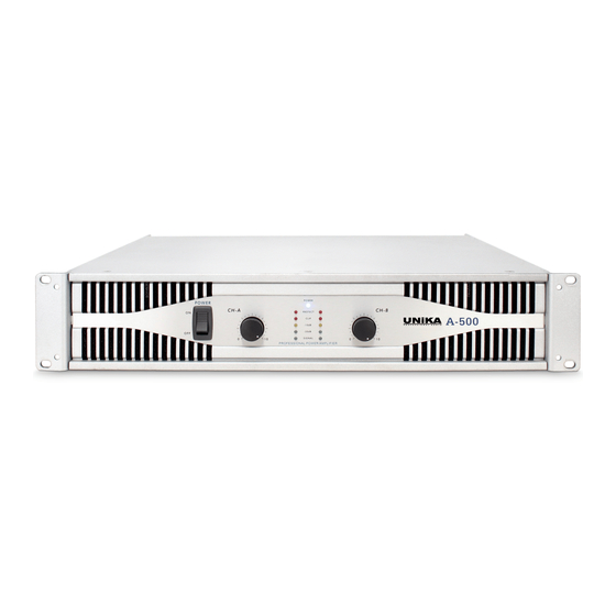
POWER
PROTECT
A-500
CLIP
-10dB
-20dB
SIGNAL
0
10
POWER
LIMITER
ON
PROTECT
A-800
CLIP
-10dB
-20dB
SIGNAL
0
10
LIMITER
POWER
ON
PROTECT
A-1300
CLIP
-10dB
-20dB
SIGNAL
0
10
UNiK A
UNiK A
UNiK A
Advertisement
Table of Contents


Need help?
Do you have a question about the A-500 and is the answer not in the manual?
Questions and answers