Table of Contents
Advertisement
Quick Links
UNiK A
Professional Power Amplif iers
POWER
CH
1
CH
2
CH
3
CLIP
CLIP
CLIP
UA-3000
UNiK A
SIGNAL
SIGNAL
SIGNAL
OFF
ON
0
10
0
10
0
10
PROFESSIONAL AMPLIFIER
POWER
CH
1
CH
2
CH
3
CH
4
CLIP
CLIP
CLIP
CLIP
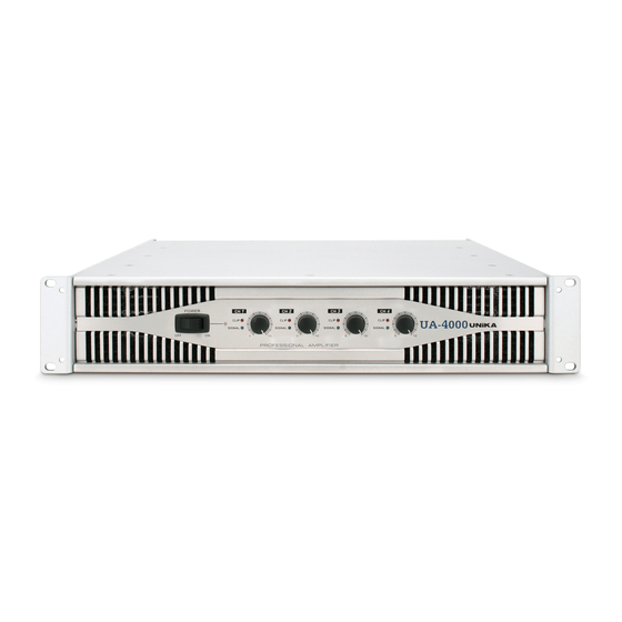
UA-4000
UNiK A
SIGNAL
SIGNAL
SIGNAL
SIGNAL
OFF
ON
0
10
0
10
0
10
0
10
PROFESSIONAL AMPLIFIER
Index
02 Introduction
03 Front Panel
04 UA-3000 Rear Panel
05 UA-4000 Rear Panel
0
6 Set Up
08 Operating Modes
11
Protection
12 Specifications
User Instructions
This booklet contains important information concerning the proper and safe operation of your new amplifier..
UA-Series
UA-3000 / UA-4000
Made in Taiwan
Advertisement
Table of Contents

Related Manuals for Unika UA-3000


Summary of Contents for Unika UA-3000
- Page 1 This booklet contains important information concerning the proper and safe operation of your new amplifier.. Index UA-Series UA-3000 / UA-4000 Made in Taiwan 02 Introduction 03 Front Panel 04 UA-3000 Rear Panel 05 UA-4000 Rear Panel 6 Set Up 08 Operating Modes Protection 12 Specifications...
- Page 2 IMPORTANT SAFETY INSTRUCTIONS UA-3000/UA-4000 This symbol is intended to alert the user to the presence of This symbol is intended to alert the user of non insulated "dangerous voltage" within the product's the presence of important operating and CAUTION enclosure that may be of sufficient magnitude to constitute...
-
Page 3: Important Precautions
Protection Specifications IMPORTANT PRECAUTIONS INTRODUCTION To reduce the risk of electrical shock or fire, do not expose this unit rain or Congratulations and thank you for purchasing UA-3000/UA-4000 moisture. amplifiers. These amplifiers are representation of UNiKA’s continuing Do not spill water or other liquids into or on to your unit. -
Page 4: Front Panel
This rotary knob is used to control the output signal level of the channel. turned off, this is normal. Turning the knob in a clockwise direction will increase output signal level. UNiKA Logo and Model No - UA series have 2 types of 2U models UA- 3000 / UA-4000. page 3... -
Page 5: Rear Panel
UNiKA UA-3000/UA-4000 Rear Panel Introduction Front Panel Set Up Operating Modes Protection Specifications UA-3000 REAR PANEL INPUT CH 3 Ext Input CH 3 CH 2 CH 1 BREAKER SUB WOOFER INPUT FREQUENCY SELECT SUB ON EXT INPUT BYPASS CH 1 & CH 2... - Page 6 UNiKA UA-3000/UA-4000 Rear Panel Introduction Front Panel Set Up Operating Modes Protection Specifications UA-4000 REAR PANEL CH3 INPUT SUB WOOFER CH4 & CH3 CH2 & CH1 CH1 & CH2 CH 4 CH 3 CH 2 CH 1 BREAKER INPUT INPUT...
- Page 7 20ft. When constructing your own XLR cables follow the pin configuration described below for proper connections. RCA CONNECTOR (Figure 6) – For UA-3000 only This is the input terminal of the audio signal, RCA connector is unbalanced specification. For cable runs shorter than 20ft., you may choose the RCA unbalanced input option.
- Page 8 (or channel CH 4 CH 3 INPUT BRIDGE PARALLEL three) positive output terminal for the speaker's positive connection. UA-3000 power amplifier does not have Mono Bridge operation mode. 20Hz 200Hz FREQUENCY 4 CHANNEL INPUT BALANCE BRIDGE MONO...
-
Page 9: Operating Modes
This mode sends low frequencies to your speakers without the use of an external cross-over. The subwoofer operation can be operated in mono only. Set the subwoofer mode switch to the “ON” position. Use the frequency selector to adjust the subwoofer output frequency from 20Hz to 200Hz. UA-3000 Rear Panel INPUT CH 3... - Page 10 UNiKA UA-3000/UA-4000 Operating Modes Introduction Front Panel Rear Panel Set Up Protection Specifications UA-3000 Rear Panel INPUT CH 3 Ext Input CH 3 CH 2 CH 1 BREAKER SUB WOOFER INPUT FREQUENCY SELECT SUB ON EXT INPUT BYPASS CH 1 & CH 2...
- Page 11 UNiKA UA-3000/UA-4000 Operating Modes Introduction Front Panel Rear Panel Set Up Protection Specifications Set to Bridge UA-4000 Rear Panel CH3 INPUT SUB WOOFER CH4 & CH3 CH2 & CH1 CH1 & CH2 CH 4 CH 3 CH 2 CH 1...
- Page 12 UNiKA UA-3000/UA-4000 Protection Introduction Front Panel Rear Panel Set Up Operating Modes Specifications PROTECTION 1. Switch ON Mute Protection The mute circuit is used at the inputs when the unit switched ON, output of between a few seconds the amplifier will be muted. This is done so that turn-on/ off noises from mixers and other gear is blocked in case the entire system is powered up at once.
-
Page 13: Specifications
UNiKA UA-3000/UA-4000 Specifications Introduction Front Panel Rear Panel Set Up Operating Modes Protection UA-SERIES AMPLIFIER SPECIFICATIONS UA - 3000 UA - 4000 3 Ch Driven 4 Ch Driven CH1/2 R.M.S. Output Power 4ohms 340W 700W 4ohms 340W 4ohms/8ohms 1KHz 1% THD... - Page 14 UNiK A Professional Power Amplif iers...
Need help?
Do you have a question about the UA-3000 and is the answer not in the manual?
Questions and answers