Table of Contents
Advertisement
Quick Links
UNiK A
POWER
ON
OFF
0
10
PROFESSIONAL POWER AMPLIFIER
LIMITER
POWER
ON
ON
OFF
0
10
PROFESSIONAL POWER AMPLIFIER
LIMITER
POWER
ON
ON
OFF
0
10
PROFESSIONAL POWER AMPLIFIER
User Instructions
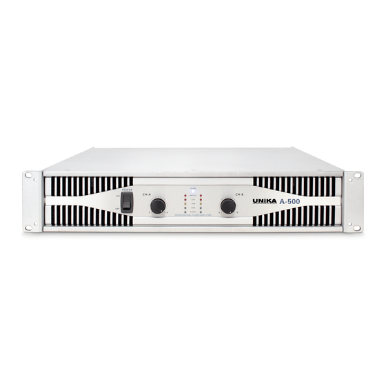
Professional Power Amplif iers
POWER
PROTECT
A-500
CLIP
-10dB
-20dB
SIGNAL
0
10
POWER
LIMITER
ON
PROTECT
A-800
CLIP
-10dB
-20dB
SIGNAL
0
10
LIMITER
POWER
ON
PROTECT
A-1300
CLIP
-10dB
-20dB
SIGNAL
0
10
UNiK A
UNiK A
UNiK A
Advertisement
Table of Contents

Related Manuals for Unika A-1300


Summarization of Contents
General Safety Warnings
Electrical Hazard Alerts
Alerts regarding dangerous voltages and risk of electric shock within the enclosure.
Manual and Warning Alerts
Notifies users of important operating/maintenance instructions and general warnings.
Operational Safety Instructions
Risk of Electric Shock Warnings
Explicit cautions against opening the unit to prevent electric shock.
Usage and Environmental Precautions
Advice on proper usage, ventilation, and avoiding exposure to elements.
Important Precautions
Handling and Usage Warnings
Precautions on preventing damage, proper handling, cleaning, and heat management.
Introduction and Unpacking
Welcome message, product overview, and guidance for unpacking the amplifier.
Installation Guidelines
Instructions for mounting the amplifier securely in a standard 19-inch rack.
Front Panel Controls Overview
Power and Limiter Controls
Switches for power and limiter functions on channels 1 and 2.
Indicators and Signal Levels
LED indicators for signal, clip, protect status, and signal level monitoring.
Gain Adjustment and Cooling
Rotary knobs for channel gain and essential cooling vents.
A-500 Rear Panel Connections
Input and Output Jacks
Details on XLR and 1/4" input jacks and 5-way binding post speaker outputs.
Ancillary Rear Panel Features
Information on cooling fan, circuit breaker, and stereo/mono bridge selector.
AC Power Input
Connection point for the AC power cord, specifying voltage requirements.
A-800 Rear Panel Features
Input Jacks and Thru Connectors
XLR and 1/4" input jacks, including XLR THRU for signal pass-through.
Speaker Outputs and Mode Switch
Binding post speaker outputs and the switch for stereo or mono bridge operation.
Low Cut Filter and Ground Lift
Switches for low-cut filter adjustment and ground lift functionality.
A-1300 Rear Panel Configuration
Subwoofer Mode and Frequency Adjust
Switches and pots for subwoofer mode and frequency adjustment on channels.
Input/Output and Filter Settings
Input/output jacks, low-cut filter dip switches, and frequency adjustment controls.
Mode Selection and Power Input
Mono-bridge/stereo switch, fuse holder, ground lift, and AC power input.
Setting Up the Amplifier
Input Connector Options
Details on XLR and 1/4" input connectors and pin configurations for balanced/unbalanced signals.
Output Connection Types
Guide to connecting speakers using binding posts, banana plugs, or bare wire.
Speaker Connection Methods
Bare Wire and Spade Connector Use
Instructions for connecting speakers using bare wire or spade connectors.
Mono Bridge Speaker Wiring
Specific wiring instructions for mono bridge operation using positive terminals.
Operating Modes and Performance
Stereo and Mono Bridge Operation
Detailed setup for stereo and mono bridge modes, including cautions.
Limiter Functionality
Explanation of the built-in limiter, its purpose, and how it activates.
Output Load Safety Levels
Guidance on safe power levels for 8, 4, and 2-ohm speaker loads.
Short Circuit Protection
Description of the amplifier's protection against output short circuits.
Amplifier Protection and Filters
Thermal and Input/Output Protection
Details on thermal protection, input/output circuits, and operating voltage.
Gain Controls and Low Cut Filter
Explanation of gain controls and the adjustable low-cut filter settings.
Need help?
Do you have a question about the A-1300 and is the answer not in the manual?
Questions and answers