Table of Contents
Advertisement
Quick Links
User Instructions
This booklet contains important information concerning the proper and safe operation of your new amplifier..
TD-14000
AMPLIFIER
Made in Taiwan
UNiKA
TD-14000
P R O F E S S I O N A L A U D I O
POWER
Index
01 Precautions
02 Introduction
03 Front Panel
04 Rear Panel
05 Operation and Performance
UNiKA
P R O F E S S I O N A L A U D I O
Advertisement
Table of Contents

Related Manuals for Unika TD-14000


Summary of Contents for Unika TD-14000
-
Page 1: User Instructions
User Instructions This booklet contains important information concerning the proper and safe operation of your new amplifier.. TD-14000 AMPLIFIER Made in Taiwan UNiKA TD-14000 P R O F E S S I O N A L A U D I O... -
Page 2: Important Precautions
TD-14000 AMPLIFIER Precautions Introduction Front Panel Rear Panel Operation and Performance This symbol, wherever it CAUTION appears, alerts you to the RISK OF ELECTRIC SHOCK presence of uninsulated DO NOT OPEN dangerous voltage inside the enclosure - voltage that may be... -
Page 3: Introduction
Introduction Congratulations and thank you for purchasing TD14000 amplifier. This amplifier is a representation of UNiKA’s continuing commitment to produce the best and highest quality audio products at an affordable price. These amplifiers are designed to provide a big impact in sound reproduction. Please read and understand this manual completely before attempting to operate your new amplifier. -
Page 4: Front Panel Control
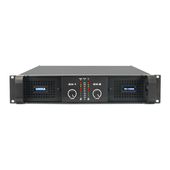
TD-14000 AMPLIFIER Front Panel Precautions Introduction Rear Panel Operation and Performance Front Panel Control UNiKA TD-14000 P R O F E S S I O N A L A U D I O POWER Figure 1 1. Carry/protection handle - Both handles can be used to carry the amplifier, they also act as protection for the front panel. -
Page 5: Rear Panel Control
TD-14000 AMPLIFIER Rear Panel Precautions Introduction Front Panel Operation and Performance Rear Panel Control PUSH PUSH ~220V 60Hz ~110V 60Hz DIP ON 1 2 3 4 5 6 1 2 3 4 5 6 7 8 Figure 2 1. AC line cord - Mains input 115V or 220V operation (Not selectable 2. -
Page 6: Operation And Performance
TD-14000 AMPLIFIER Operation and Performance Precautions Introduction Front Panel Rear Panel Operation and Performance Signal flow blocks All TD14000 amplifiers have the same signal flow, and the same feature sets. The only internal differences are in the maximum output current per channel and VPL settings. - Page 7 TD-14000 AMPLIFIER Operation and Performance Precautions Introduction Front Panel Rear Panel Headroom, ensitivity and VPL/Gain settings. The input amplifier and limiter system I designed to accommodate extreme of performance. Typically, exceeding maximum input by much as +10dB will only result in a 1% increase in distortion.
-
Page 8: Unbalanced Input Connection
TD-14000 AMPLIFIER Operation and Performance Precautions Introduction Front Panel Rear Panel Audio Input and Output connections Balanced Input connections The XLR input connectors are electronically balanced, and wired according to the IEC 268 standard (pin2 = hot). XLR input connector should be wired as follows:... -
Page 9: Binding Post(Bp)Output Connectors
Binding Post outputs The outputs on The TD-14000 amplifiers produce high voltage. Do not connect or disconnect the loudspeaker cables while the mains power is on. Never operate the amplifier with any portion of bare loudspeaker wore exposed. -
Page 10: Amplifier Gain
3 dB steps. Individual channel fine level adjustment is available using the potentiometers on the front panel. The unique adjustable input gain feature of the TD-14000 makes it easier to attain the optimum balance between headroom and signal-to-noise ratio in the signal path. A weak signal at the input might require the gain to be raised in order to achieve maximum output power with the lowest signal-to-noise ratio. -
Page 11: Protection, Faults And Warnings
If there is no short circuit present, then the NOTE condition may be rectified by lowering the VPL or input levels. Protection, faults and warnings The TD-14000 amplifier incorporate a sophisticated and comprehensive set of protection features. Faults and warnings are indicted on the front panel. -
Page 12: Safe Operating Area Detector(Soad)
TD-14000 AMPLIFIER Operation and Performance Precautions Introduction Front Panel Rear Panel Safe Operating Area Detector(SOAD) The Safe Operating Area Detector(SOAD) compares output voltage against output current to enure that the output transistors are working inside their safe operating area. The SOAD provides fault monitoring and input to the Current Peak Limiter 9CPL0. The SOAD has no dedicated indicator, and it operation is revealed only in conjunction with features such as the CPL. -
Page 13: High-Impedance Warning(Open Load)
TD-14000 AMPLIFIER Operation and Performance Precautions Introduction Front Panel Rear Panel The Attack time for the VHF protection is increasingly shorter at higher frequencies. For example, an ultrasonic continuous signal will cause the outputs to mute rapidly, where it will take several milliseconds for a 10 kHz continuous signal to trigger the output mute. -
Page 14: Temperature Protection
TD-14000 AMPLIFIER Operation and Performance Precautions Introduction Front Panel Rear Panel If the CPL turns constant orange, the output is muted, and the -4dB signal LED is on, then the amplifier has gone into maximum current protection. This... -
Page 15: Level Adjust
TD-14000 AMPLIFIER Operation and Performance Precautions Introduction Front Panel Rear Panel Front-panel monitoring and adjustments Level indicators The front-paneldisplays an array of ten LED indicators for level and status monitoring of each amplifier channel. Indications related to signal levels are as follows: ... -
Page 16: Channel Indicators
TD-14000 AMPLIFIER Operation and Performance Precautions Introduction Front Panel Rear Panel Channel Indicators: Bridge mode (yellow) indicates if two channels are bridged using the DIP-switch on the rear panel. CPL, Current Peak Limiter (orange), when flashing indicates the maximum possible current draw has been reached. - Page 17 NOTE...
- Page 18 UNiKA P R O F E S S I O N A L A U D I O...
Need help?
Do you have a question about the TD-14000 and is the answer not in the manual?
Questions and answers