
Related Manuals for Quietside QS09-VP115


Summary of Contents for Quietside QS09-VP115
-
Page 1: Service Manual
Service Manual Model: QS09-VJ115 QS12-VJ115 QS09-VP115 QS12-VP115 (Refrigerant R410A) -
Page 2: Table Of Contents
Service Manual Table of Contents Part : Technical Information Ⅰ ..........1 1. Summary ........................1 2. Specifications ......................2 2.1 Specification Sheet ......................2 2.2 Operation Characteristic Curve ..................4 2.3 Capacity Variation Ratio According to Temperature ............4 2.4 Noise Curve ........................ - Page 3 Service Manual 8.5 Installation of Indoor Unit ....................26 8.6 Installation of Outdoor Unit ....................29 8.7 Vacuum Pumping and Leak Detection ................30 8.8 Check after Installation and Test operation ..............30 9. Maintenance ......................31 9.1 Troubleshooting for Normal Malfunction ................31 9.2 Error Code List .........................
-
Page 4: Part Ⅰ : Technical Information
Service Manual Part : Technical Information Ⅰ 1. Summary Indoor Unit: QS09-VJ115 QS12-VJ115 Outdoor Unit: QS09-VP115 QS12-VP115 Remote Controller: YB1FAF MODE ON/OFF CLOCK TIMER ON X-FAN TEMP TIMER OFF TURBO SLEEP LIGHT Technical Information... -
Page 5: Specifications
Service Manual 2. Specifications 2.1 Specification Sheet QS09-VJ115 QS12-VJ115 Model QS09-VP115 QS12-VP115 Product Code CB16300021_K90639 CB16300041_K90639 Rated Voltage Power Rated Frequency Supply Phases Power Supply Mode Outdoor Outdoor Cooling Capacity(Min~Max) Btu/h 9000(4436~11997) 12000(4500~13999) Heating Capacity(Min~Max) Btu/h 9500(3412~12488) 13000(3753~14498) Cooling Power Input(Min~Max) - Page 6 Service Manual Outdoor Unit Model QS09-VP115 QS12-VP115 Outdoor Unit Product Code CB190W0041_K90639 CB190W0061_K90639 ZHUHAI LANDA ZHUHAI LANDA Compressor Manufacturer COMPRESSOR CO., LTD COMPRESSOR CO., LTD Compressor Model QXA-A091zE190 QXA-A091zE190 Compressor Oil FVC68D/RB68EP FVC68D/RB68EP Compressor Type Rotary Rotary Compressor LRA. Compressor RLA 16.03...
-
Page 7: Operation Characteristic Curve
Service Manual 2.2 Operation Characteristic Curve 25.0 Conditions 25.0 Conditions Indoor: DB80°F/WB67°F Indoor: DB70°F/WB60°F 22.5 22.5 QS09-VJ115 QS09-VP115 Outdoor: DB95°F/WB75°F Outdoor: DB47°F/WB43°F 20.0 20.0 Cooling: Indoor air flow: TURBO Heating: Indoor air flow: TURBO 17.5 17.5 Pipe length: 25 ft. -
Page 8: Noise Curve
Service Manual 2.4 Noise Curve Outdoor side noise Indoor side noise when blowing QS09-VP115 QS12-VJ115 QS12-VP115 QS09-VJ115 Turbo Middle High Indoor fan motor rotating speed Compressor frequency/Hz 2.5 Cooling and Heating Data Sheet in Rated Frequency Cooling: Pressure of gas pipe... -
Page 9: Outline Dimension Diagram
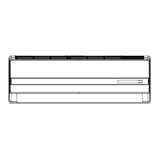
Service Manual 3. Outline Dimension Diagram 3.1 Indoor Unit 33 1/4" 7" 5 1/8" 21 1/3" 6 4/5" 2 1/6" 2 1/6" 2 5/7" 4 7/8" Unit:inch Technical Information... -
Page 10: Outdoor Unit
Service Manual 3.2 Outdoor Unit 30 5/9" 10 1/8" 21 1/4" Unit:inch Model QS09-VP115 33 2/5" 21 1/4" 12 3/5" QS12-VP115 33 2/5" 23 1/3" 12 3/5" Technical Information... -
Page 11: Refrigerant System Diagram
expansion valve Service Manual COOLING 4. Refrigerant System Diagram Outdoor unit Indoor unit Gas pipe side Valve 4-Way valve Di s charge Heat Suction exchanger (evaporator) Heat exchanger Liquid pipe (condenser) side Valve Electron Strainer Strainer expansion valve COOLING HEATING Connection pipe specification: Liquid : 1/4"... -
Page 12: Electrical Part
Service Manual 5. Electrical Part 5.1 Wiring Diagram ●Instruction Symbol Symbol Color Symbol Symbol Color Symbol Name White Green Jumper cap Yellow Brown COMP Compressor Blue Grounding wire YEGN Yellow/Green Black Violet Orange Note: Jumper cap is used to determine fan speed and the swing angle of horizontal lover for this model. ●... -
Page 13: Outdoor Unit Wiring Diagram
Service Manual ● Outdoor Unit COMP EXHAUST TUBE OUTROOM W14 BU COMP W19 RD TEM.SENSOR TEM.SENSOR TEM.SENSOR W8 YEGN W3YEGN W10 RD AC-N3 AC-N4 AC-L3 AC-L2 OVERHEAT INDOOR W4 BK COMU UNIT FILTER W2 BU W11 WH N(1) N(1) AC-N W12 RD W1 BN AC-L1... -
Page 14: Pcb Printed Diagram
Service Manual 5.2 PCB Printed Diagram Indoor unit ● Top view 1 Neutral wire interface 2 Transformer input 3 PG motor interface Neutral and live wire communication interface 5 Auto button 6 PG motor feedback interface 7 Up&down swing interface 8 Jumper cap Indoor ambient temp. - Page 15 Service Manual Outdoor unit ● Top view Port of compressor Port of power supply Port of electric expansion Port of DC fan motor electric heating band neutral wire valve Port of compressor Port of AC fan motor Port of earthing wire Port of compressor output electric heating band Port of power supply...
-
Page 16: Function And Control
Service Manual 6. Function and Control 6.1 Remote Controller Introduction Buttons on Remote Controller ON/OFF Button MODE Button +/- Button FAN Button Button CLOCK Button TIMER ON/TIMER-OFF Button X-FAN Button TEMP Button TURBO Button LIGHT Button SLEEP Button Introduction for Icons on Display Screen Set fan speed Operation mode Send signal... - Page 17 Service Manual ● When selecting auto mode, air conditioner will operate automatically according to exfactory setting. Set temperature can’t be adjusted and will not be displayed as well. Press“FAN” button can adjust fan speed. Press " " button can adjust fan blowing angle. ●...
-
Page 18: Function Introduction For Combination Buttons
Service Manual controller blinks. Press "+" or "-"button to adjust TIMER ON setting. After each pressing "+" or "-"button, TIMER ON setting will increase or decrease 1min. Hold "+" or "-"button, 2s later, the time will change quickly until reaching your required time. Press “ TIMER ON”to confirm it. The word “ON" will stop blinking. " "... -
Page 19: Operation Guide
Service Manual Operation Guide 1. After putting through the power, press “ON/OFF” button on remote controller to turn on the air conditioner. 2. Press "MODE" button to select your required mode:AUTO,COOL,DRY,FAN,HEAT. 3. Press “+” or “-“ button to set your required temperature. (Temperature can’t be adjusted under auto mode). -
Page 20: Brief Description Of Modes And Functions
Service Manual 6.2 Brief Description of Modes and Functions ●Indoor Unit 1.Temperature Parameters ◆ Indoor preset temperature (Tpreset) ◆ Indoor ambient temperature (Tamb.) ◆补偿温度(T 补) 2.Basic Functions Once the unit energized,the compressor shall never be restarted except 3mins interval at least.For the first energization,if the unit is at off status before power failure, the compressor can be restarted without 3-min delay. - Page 21 Service Manual mode switchover. Protection function is the same as that in other modes. The selection method for auto operation mode in details is as below: a. When Tamb. ≥79°F, the unit operates in cooling mode. The defaulted set temperature is 77°F; b.
- Page 22 Service Manual the unit will keep operating at that temperature. 2. Heating mode: 2.1 When initial set temperature is 61°F, the unit will operate at that temperature; 2.2 When initial set temperature range is 63~68°F, if turning on sleep function, temperature will decrease 1.8°F for every hour. After 1.8°F has been decreased, the temperature will not change.
- Page 23 Service Manual (9) Display 1. Upon energization within 2s, the unit will display all icons. Under standby state, running indicating mark is displayed. If the unit is started by remote controller, running indicating mark gives off light; meanwhile, the mark of current running mode will be di played. If the light but- ton is turned off, no mark will be displayed.
-
Page 24: Maintenance
Service Manual 9. Maintenance 9.1 Troubleshooting for Normal Malfunction Note: When replacing the controller, make sure insert the wire jumper into the new controller, otherwise the unit will display C5. Measure insulation resistance The breaker trips at once when it to ground to see if there is any is set to “ON”. - Page 25 Service Manual Improper set of temperature Adjust set temperature If cooling (heating) load is Check the forecasted load of cooling (heating) proper Check and fill the leakage, then The refrigerant has leakage or is vacuumize it and supplement the re- insufficient frigerant as required Leakage between the high pres-...
- Page 26 Service Manual The indoor fan motor is burned or breaks or has the heat protector Replace the fan motor or the defective part. malfunction. The built-in heat protector of the Replace the fan motor The fan does not motor breaks frequently because the run when it is set motor is abnormal.
- Page 27 Service Manual The torque of the swing motor is not enough First, check whether the connection is Wrong connection The swing fan wrong. If no, replace the parts does not run. The controller is damaged(IC2003 is damaged, the swing relay can not close, etc) C o n t r o l l e r m a l f u n c t i o n ( I C 2 0 0 3 Change controller...
-
Page 28: Error Code List
Service Manual 9.2 Error Code List Display Method of Outdoor Display Method of Indoor Unit Unit Indicator has 3 kinds of Indicator Display (during display status and during Malfunction blinking, ON 0.5s and OFF Dual-8 A/C status Possible Causes blinking, ON 0.5s and OFF Name 0.5s) Code... - Page 29 Service Manual Display Method of Outdoor Display Method of Indoor Unit Unit Indicator has 3 kinds of Indicator Display (during display status and during Malfunction blinking, ON 0.5s and OFF Dual-8 A/C status Possible Causes blinking, ON 0.5s and OFF Name 0.5s) Code...
- Page 30 Service Manual Display Method of Outdoor Display Method of Indoor Unit Unit Indicator has 3 kinds of Indicator Display (during display status and during Malfunction blinking, ON 0.5s and OFF Dual-8 A/C status Possible Causes blinking, ON 0.5s and OFF Name 0.5s) Code...
- Page 31 Service Manual Display Method of Outdoor Display Method of Indoor Unit Unit Indicator has 3 kinds of Indicator Display (during display status and during Malfunction blinking, ON 0.5s and OFF Dual-8 A/C status Possible Causes blinking, ON 0.5s and OFF Name 0.5s) Code...
- Page 32 Service Manual Display Method of Outdoor Display Method of Indoor Unit Unit Indicator has 3 kinds of Indicator Display (during display status and during Malfunction blinking, ON 0.5s and OFF Dual-8 A/C status Possible Causes blinking, ON 0.5s and OFF Name 0.5s) Code...
- Page 33 Service Manual Display Method of Outdoor Display Method of Indoor Unit Unit Indicator has 3 kinds of Indicator Display (during display status and during Malfunction blinking, ON 0.5s and OFF Dual-8 A/C status Possible Causes blinking, ON 0.5s and OFF Name 0.5s) Code...
- Page 34 Service Manual Display Method of Indoor Unit Display Method of Outdoor Unit Indicator Display (during Indicator has 3 kinds of display blinking, ON 0.5s and OFF status and during blinking, ON Dual-8 Malfunction A/C status Possible Causes 0.5s) 0.5s and OFF 0.5s Code Name Operation...
-
Page 35: Troubleshooting For Main Malfunction
Service Manual 9.3 Troubleshooting for Main Malfunction (1) Capacitor charge fault (Fault with outdoor unit) (AP1 below refers to the outdoor control panel) Main Check Points: ●Use AC voltmeter to check if the voltage between terminal L and N on the wiring board is within 210VAC~240VAC. ●Is the reactor (L) correctly connected? Is the connection loose or fallen? Is the reactor (L) damaged? Fault diagnosis process: Turn on the unit... - Page 36 Service Manual (2) IPM Protection, Out-of-step Fault, Compressor Phase Overcurrent (AP1 below refers to the outdoor control panel) Main check points: ●Is the connection between control panel AP1 and compressor COMP secure? Loose? Is the connection in correct order? ●Is the voltage input of the machine within normal range? (Use AC voltmeter to measure the voltage between terminal L and N on the wiring board XT) ●Is the compressor coil resistance normal? Is the insulation of compressor coil against the copper tube in good condition? ●Is the working load of the machine too high? Is the radiation good?
- Page 37 Service Manual (3)High temperature and overload protection diagnosis (AP1 hereinafter refers to the control board of the outdoor unit) Mainly detect: ●Is outdoor ambient temperature in normal range? ●Are the outdoor and indoor fans operating normally? ●Is the heat dissipation environment inside and outside the unit good? Fault diagnosis process: Overheat and high temperature protection...
- Page 38 Service Manual (4) Start-up failure (following AP1 for outdoor unit control board) Mainly detect: ●Whether the compressor wiring is connected correct? ●Is compressor broken? ●Is time for compressor stopping enough? Fault diagnosis process: Power on the unit Restart it up after Is stop time of the compressor 3 minutes longer than 3 minutes?
- Page 39 Service Manual (5) Out of step diagnosis for the compressor (AP1 hereinafter refers to the control board of the outdoor unit) Mainly detect: ●Is the system pressure too high? ●Is the input voltage too low? Fault diagnosis process: Out of step occurs in Out of step occurs once the operation unit is powered on.
- Page 40 Service Manual (6)Overload and air exhaust malfunction diagnosis (following AP1 for outdoor unit control board) Mainly detect: ●Is the PMV connected well or not? Is PMV damaged? ●Is refrigerant leaked? Fault diagnosis process: 20 minutes after the complete unit is powered off Is the terminal FA for the Connect the...
- Page 41 Service Manual (7)Power factor correct or (PFC) fault (a fault of outdoor unit) (AP1 hereinafter refers to the control board of the outdoor unit) Mainly detect: ●Check if the reactor (L) of the outdoor unit and the PFC capacitor are broken Fault diagnosis process: Start Check wiring of the...
- Page 42 Service Manual (8) Communication malfunction: (following AP1 for outdoor unit control board) Mainly detect: ●Is there any damage for the indoor unit mainboard communication circuit? Is communication circuit damaged? ●Detect the indoor and outdoor units connection wire and indoor and outdoor units inside wiring is connect well or not, if is there any damage? Fault diagnosis process: Start...
-
Page 43: Exploded View And Parts List
Service Manual 10. Exploded View and Parts List 10.1 Indoor Unit Installation and Maintenance... - Page 44 Service Manual Part Code Description QS09-VJ115 QS12-VJ115 Product Code CB163N0021_K90639 CB163N0041_K90639 Temperature Sensor 390000591 390000591 Temperature Sensor 390000451 390000451 Remote Controller 305100482_K90639 305100482_K90639 Evaporator Support 24212091 24212091 Ring of Bearing 26152022 26152022 O-Gasket sub-assy of Bearing 7651205102 7651205102 Cross Flow Fan 10352017 10352017 Rear Case assy...
-
Page 45: Outdoor Unit
Service Manual 10.2 Outdoor Unit QS09-VP115 Installation and Maintenance... - Page 46 Service Manual Part Code Description QS09-VP115 Product Code CB190W0041_K90639 Front Grill 01473012 Cabinet 0143305801P Axial Flow Fan 10333012 Electrical Heater 76510010 Fan Motor 15013160 Chassis Sub-assy 01203881P Drainage Connecter 06123401 Compressor Gasket 76710302 Electrical Heater(Compressor) 76510009 Compressor and Fittings 00103862...
- Page 47 Service Manual QS12-VP115 Installation and Maintenance...
- Page 48 Service Manual Part Code Description QS12-VP115 Product Code CB190W0061_K90639 Front Grill 01473012 Front Panel 0153501201 Axial Flow Fan 10333012 Fan Motor 15013160 Electrical Heater 76510010 Chassis Sub-assy 01203881P Drainage Connecter 06123401 Electrical Heater(Compressor) 76510009 Compressor and Fittings 00103862 Compressor Gasket 76710302 Magnet Coil 4300040021...
-
Page 49: Removal Procedure
Service Manual 11. Removal Procedure Caution: discharge the refrigerant completely before removal. 11.1 Removal Procedure of Indoor Unit Steps Procedure 1.Remove panel Open the front panel.Push the rotor shaft on both sides of the panel to make it separate from the groove .Remove the panel. - Page 50 Service Manual Steps Procedure 4.Remove electric box assy Remove the screws of the electric box assy.Remove the screws at the joint of the earthing wire and evaporator.Loosen the clasp at the joint of the electric box cover and the electric box.Remove the 2 screws of the display.Remove the electric box assy.
- Page 51 Service Manual Steps Procedure 6.Remove motor and cross flow blade Remove screws of step motor and then remove the motor. Remove the screw of the motor clamp and then remove the clamp. Remove the screws at the joint of the cross flow blade and the motor.
-
Page 52: Removal Procedure Of Outdoor Unit
Service Manual 11.2 Removal Procedure of Outdoor Unit QS09-VP115 Steps Procedure 1.Remove valve cover and handle handle Twist off the screws used for valve cover and handle, pull the valve cover and handle upward to remove it. valve cover 2.Remove top cover... - Page 53 Service Manual Steps Procedure 4.Remove front panel front panel Remove connection screws connecting the front panel with the chassis and the motor support, and then remove the front panel. 5.Remove right side plate right side plate Remove connection screws connecting the right side plate with the valve support and the electric box.
- Page 54 Service Manual Steps Procedure 8.Remove motor and motor support Remove the nut the blade and axial blade thenremove the axial blade. 8.Remove motor and motor support Remove the 4 tapping screws motor support the motor.Pull out the lead-out wire and remove themotor.
- Page 55 Service Manual Steps Procedure 10.Remove gas valve and liquid valve Twist off the 2 bolts fixing the valve sub-assy. Unsolder the soldering joint between gas valve andair-return pipe and then remove the gas valve. (note: when unsoldering the soldering joint, wrap the gas valve with wet cloth completely to avoid the damage to valve, and release all refrigerant completely at first).
- Page 56 Service Manual QS12-VP115 Steps Procedure 1.Remove valve cover and handle Twist off the screws used for fixing the valve cover and handle, pull the valve cover and handle handle upward to remove it. valve cover 2.Remove top cover top cover Remove connection screws connecting the top cover plate with the front panel and the right side plate, and then remove the top cover.
- Page 57 Service Manual Steps Procedure 4.Remove front panel front panel Remove connection screws connecting the front panel with the chassis and the motor support, and then remove the front panel. 5.Remove right side plate right side plate Remove connection screws connecting the right side plate with the valve support and the electric box.
- Page 58 Service Manual Steps Procedure 7.Remove axial flow blade Remove the nut the blade and axial blade thenremove the axial blade. 8.Remove motor and motor support Remove the 4 tapping screws motor support the motor.Pull out the lead-out wire and remove themotor. Remove the 2 tapping screws motor support.
- Page 59 Service Manual Steps Procedure 10.Remove 4-way valve assy 4-way valve assy assyUnscrew the fastening nut of the 4-way ValveAssy coil and remove the coil. Wrap the 4-way Valve Assy with wet cotton and unsolderthe 4 weld spots connecting the 4-way ValveAssy to take it out.(Note: Refrigerant shouldbe discharged Welding...
-
Page 60: Appendix
Service Manual Appendix: Appendix 1: Reference Sheet of Celsius and Fahrenheit Conversion formula for Fahrenheit degree and Celsius degree: Tf=Tcx1.8+32 Set temperature Fahrenheit Fahrenheit Fahrenheit display Fahrenheit display Fahrenheit display Fahrenheit Celsius (℃) Celsius (℃) Celsius (℃) temperature temperature temperature (℉)... -
Page 61: Appendix 3: Pipe Expanding Method
Service Manual Appendix 3: Pipe Expanding Method Pipe Note: Pipe cutter Improper pipe expanding is the main cause of refrigerant leakage.Please expand the pipe according to the following steps: Leaning Uneven Burr A:Cut the pip ● Confirm the pipe length according to the distance of indoor unit and outdoor unit. ●... -
Page 62: Appendix 4: List Of Resistance For Ambient Temperature Sensor
Service Manual Appendix 4: List of Resistance for Ambient Temperature Sensor Resistance Table of Ambient Temperature Sensor for Indoor and Outdoor Units(15K) Temp(°F) Resistance(kΩ) Temp(°F) Resistance(kΩ) Temp(°F) Resistance(kΩ) Temp(°F) Resistance(kΩ) 138.1 18.75 3.848 1.071 128.6 17.93 3.711 1.039 121.6 17.14 3.579 1.009 16.39... - Page 63 Service Manual Resistance Table of Ambient Temperature Sensor for Indoor and Outdoor Units(20K) Temp(°F) Resistance(kΩ) Temp(°F) Resistance(kΩ) Temp(°F) Resistance(kΩ) Temp(°F) Resistance(kΩ) 181.4 25.01 5.13 1.427 171.4 23.9 4.948 1.386 162.1 22.85 4.773 1.346 153.3 21.85 4.605 1.307 20.9 4.443 1.269 137.2 4.289 1.233...
- Page 64 Service Manual Resistance Table of Ambient Temperature Sensor for Indoor and Outdoor Units(50K) Temp(°F) Resistance(kΩ) Temp(°F) Resistance(kΩ) Temp(°F) Resistance(kΩ) Temp(°F) Resistance(kΩ) 853.5 18.34 4.75 799.8 93.42 17.65 4.61 89.07 16.99 4.47 703.8 84.95 16.36 4.33 660.8 81.05 15.75 4.20 620.8 77.35 15.17 4.08...
- Page 65 JF00301907...
Need help?
Do you have a question about the QS09-VP115 and is the answer not in the manual?
Questions and answers