Advertisement
Quick Links
Advertisement

Related Manuals for Quietside QSHE-092


Summary of Contents for Quietside QSHE-092
-
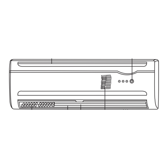
Page 15: Safety Instructions
Report all Shipping Damage to Carrier IMMEDIATELY, Check units and box exterior for damage Note to Installer This manual to is to aid the qualified HVAC contractor in the Installation and Maintenance of this Quietside R410a Ductless Mini Split Please read and understand these instructions prior to installing the unit, failure to comply with these... - Page 16 Ensure that all panels can be removed for service as required Certification All Quietside Ductless Mini Splits are certified by UL under UL standard 1995 in both Canada and the US Performance is certified by our certification under the ARI 210/240 Program...
-
Page 17: Unit Installation
Low Ambient Controller : ICM 326H must be used in Data Room or Commercial applications For a wiring diagram please contact Quietside or follow general diagram supplied with ICM Controller Probe must be located in the fin pack or on a return bend that measures approx 100 DegF during normal... - Page 18 Installation and Maintenance Manual Unit Installation (Cont) Step3 Drill Hole for Line Set etc Remove mounting bracket from the rear of the Indoor unit, then use a Phillips head screwdriver to remove the unit pipe strap, and if unit is a heat pump the defrost sensor also must be taken from the retainer so that it can be connected to the Outdoor unit.
- Page 19 DO NOT INSTALL A LIQUID LINE SIGHT GLASS OR FILTER DRIER IN THE SYSTEM Run the line set to the Outdoor unit, avoid tight bends and kinking the lines. Quietside does not recommend brazing line sets together or to the unit connections...
- Page 20 Installation and Maintenance Manual Unit Installation (Cont) Step 9 Evacuation Gauges can now be attached to the service ports - SERVICE PORTS HAVE A 5/16" CONNECTION TO THE GAUGE SET SO AN ADAPTOR IS REQUIRED Once the gauges are attached the line set can be leak checked using Nitrogen at 300 Psig Evacuate the unit down to a minimum of 200 Microns, break vacuum with Nitrogen to further leak check Re-evacuate the system down to 200 Microns or lower This is an R410A System it is essential that a deep vacuum be pulled on the system to remove all traces of...
- Page 21 The basic system installation is now complete The unit is now ready for start up - Use this time to ensure that worksite is tidy. Quietside recommend the use of Slimduct products to hide the refrigerant line set interconnects - available from your Quietside distributor...
-
Page 22: Unit Start Up
Installation and Maintenance Manual Unit Start Up With the refrigerant system completely evacuated the system can now be opened to allow the refrigerant charge in the Outdoor unit to be released into the line set The Service Valves require a 6mm and a 5mm Allen wrench respectively to undo the valve stems Remove the BRASS caps from the Service Valves Open the SUCTION line Valve first to prevent any possible oil logging of the Capillary tube This can occur if the liquid line valve is opened first with the rest of the system in a deep vacuum...
Need help?
Do you have a question about the QSHE-092 and is the answer not in the manual?
Questions and answers